Week 6 - Electronics Design
group page // repo source files // objectives
Contents
objectives >
- Linked to the group assignment page
- Use the test equipment in your lab to observe the operation of a microcontroller circuit board (in minimum, check operating voltage on the board with multimeter or voltmeter and use oscilloscope to check noise of operating voltage and interpret a data signal)
- Document your work to the group work page and reflect on your individual page what you learned
- Documented what you have learned in electronics design
- Explained problems and how you fixed them, if you make a board and it doesn’t work; fix the board (with jumper wires etc) until it does work.
- Included original design files (Eagle, KiCad, etc.)
- Included a ‘hero shot’ of your board
- Loaded a program and tested if your board works
hero shots >

Altium >
I use Altium at work, but I am also familiar with KiCad. I started out on Eagle when I began using ECAD tools, back in the day when they were still independently owned by CadSoft (honestly not that long ago).
- Altium is incredibly powerful, but it’s also kinda top heavy. It’s also properietary and requires a hefty license to use it.
- KiCad is less feature rich, but comes with an active plugins community, is FOSS, and functions as a much lighter program.
design rules >
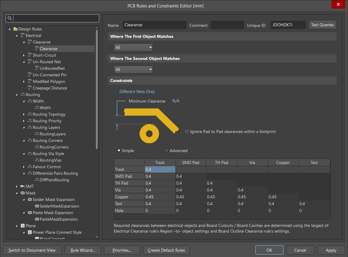
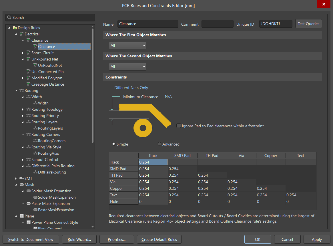
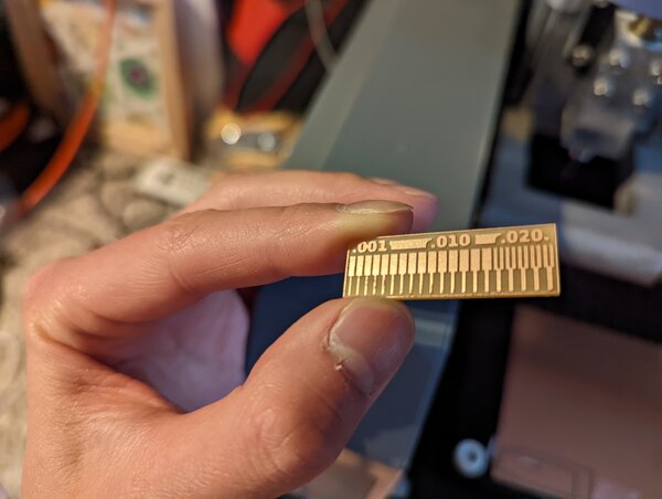
For designing PCBs to be machined on the MDX-20, the only really important rule is clearance. All other rules can be somewhat derived from that one rule. Trace width depends on benchmark results.
Clearance for the 1-64 endmill. (mm)
Clearance for the 10mil endmill. (mm)
Trace width (copied from below for ease of reference):
attempt 1 - attiny44a >
oshpark >
I know others have done this, but I originally intended to benchmark oshpark turnaround vs cnc fabbing circuits.
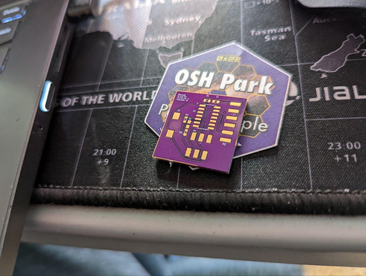
I’ll fill in more details here later, but the short version is:
- oshpark: at least 5 days for superswift fab, then shipping
- cnc: 20 minutes
mods/fab - fabtinyisp >
I was on vacation for ~a week, and given how many bits I broke for the efab unit, I focused on making sure I could fab another fabtinyisp successfully.
mods montage
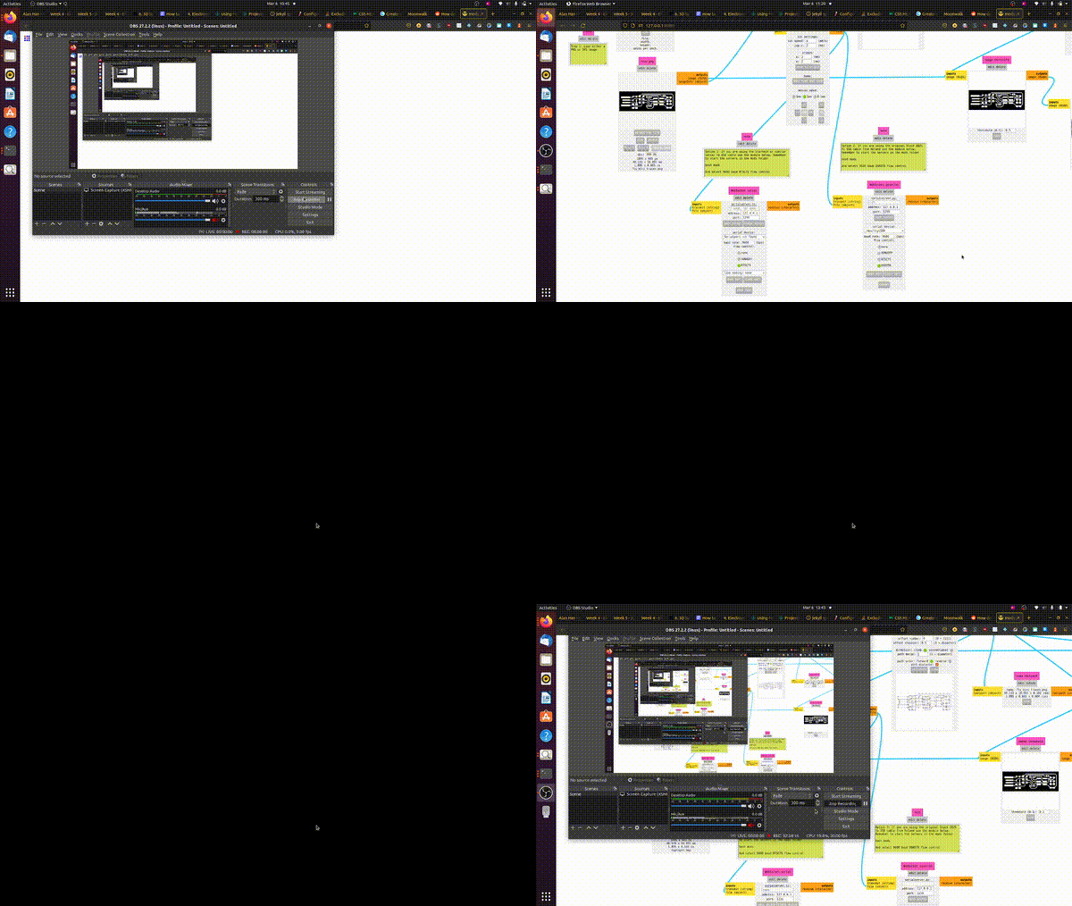
I succeeded, so I proceeded onto the actual board for this assignment.
efab - attiny >
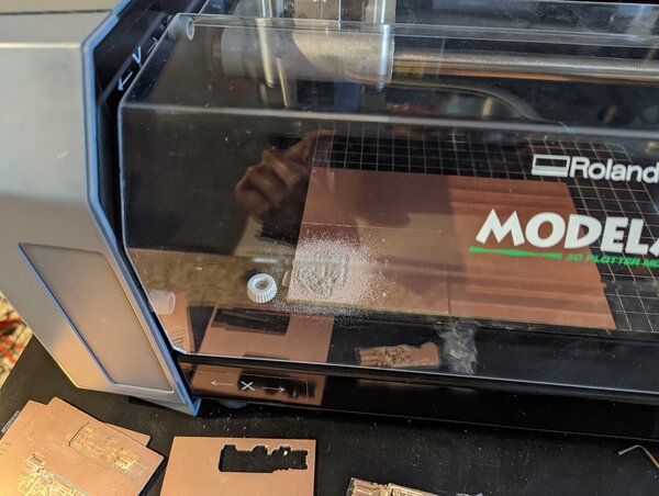
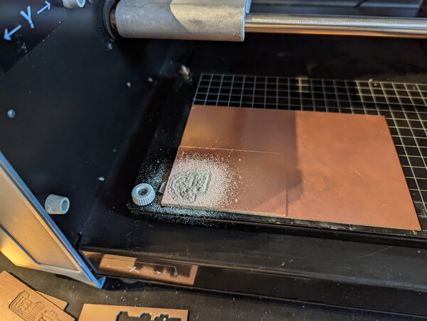
learned that I sent negative through mods, need to invert for mods to work properly. However, didn’t understand that at first. Assumed I had ignored design rules and made features too small.
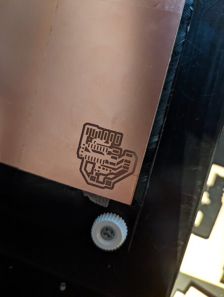
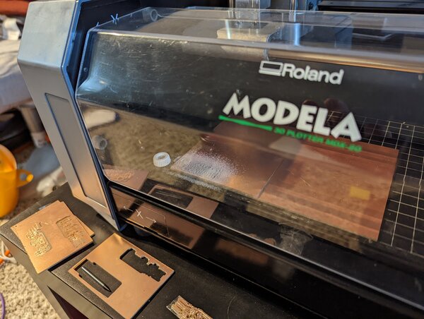
should have done this during the efab week, but better late than never! feature benchmark to see if that was the cause of my bug.
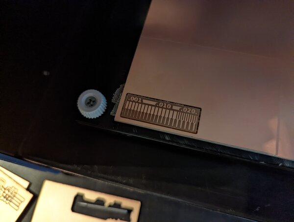 results are really good, so ruled that out.

fixed (inverted) artwork results.
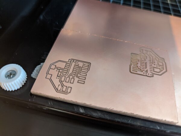
the issue >
I thought I got components from Dan for the attiny44a, but we may have had a mixup… turns out I had all the parts for the samd11c. It took me a bit, but I implemented a new board using the libraries I built for the attiny for the samd11c.
attempt 2 - samd11c >
ecad >
another design montage! (I swear I’ll document this better later, it’s late and I need to function tomorrow).
some notes:
- I spent wayyy too long looking into USB A footprint dimensions
- should refer to the USB spec directly next time; that’s where everyone else gets their info, anyways. RTFM I suppose.
exporting gerbers. learned quite a few lessons during this process (described along with cam stuff below).
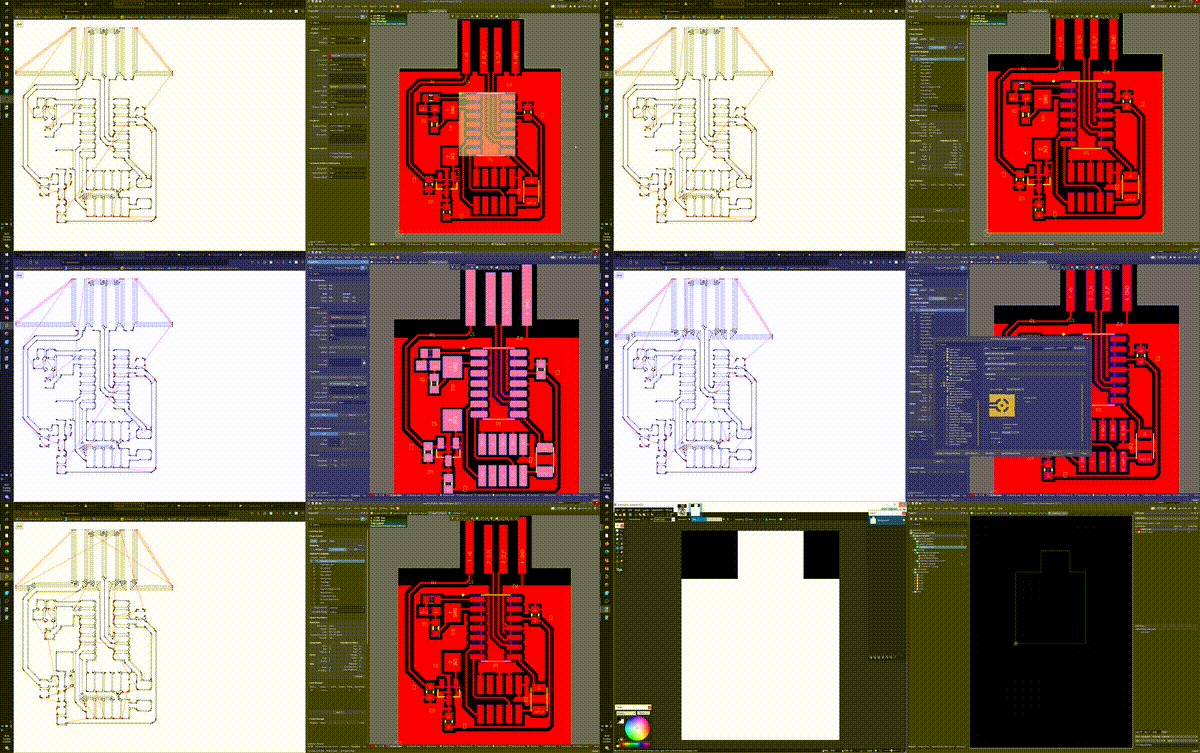
cam >
unfortunately didn’t capture the appropriate media here. a few lessons that I learned:
- remember to check DPI and set to intended value (I had 1000 from Altium bmp export)
- Altium only exports BMP (as far as I can tell), so some imagemagick conversion is required
- board outline needs to be a solid black profile? otherwise, mods won’t recognize closed shape
- traces and outline can both be run at 4mm/s w/o compromising quality/breaking bits
- polygon pours can really mess with mods pathing, since it reduces number of allowed offset passes
- clearances need to be set in multiple places in “design rules” such that they are at least as big as the bit making cuts (eg, 0.4mm or above for 1/64” bits)
- this does not affect width of trace, only clearance
efab >
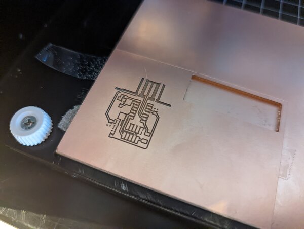
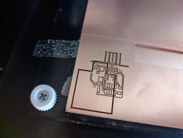
learned about another wonderful bug… seems like I should run at least one aircut before running any actual jobs with the mdx-20 (could just be a mods problem). some of the settings don’t “set” properly until after at least one run.
in this case, the origin is 10,10 by default, while I’ve been running jobs at 3,2. This explains the misalignment shown.
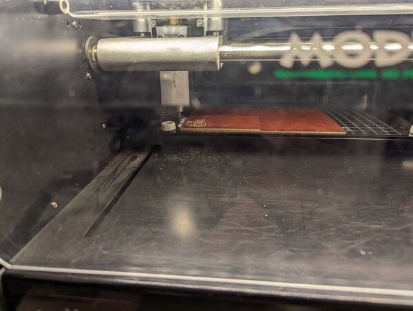
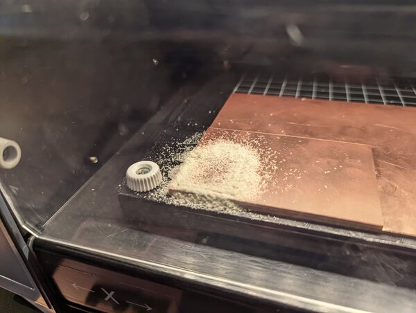
unfortunately, I was doing this prior to work in the morning. Ran out of time, and learned that you should never rush when working with CNC… broke 2x 1/32” bits.
- first one was because I neglected to tighten both collets (only one)
- second was because I was foolish to think I could swap in a good one and not expect it to break (I didn’t even zero it!)
- way easier to rush with a 3d printer than CNC. will respect amount of time required in the future.
after I came back from work, did things properly and got a great result.
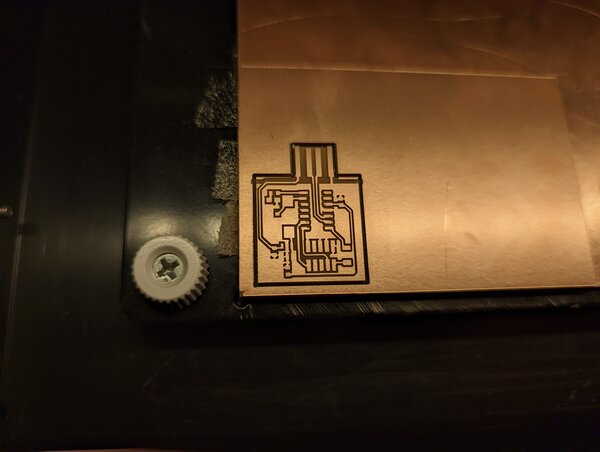
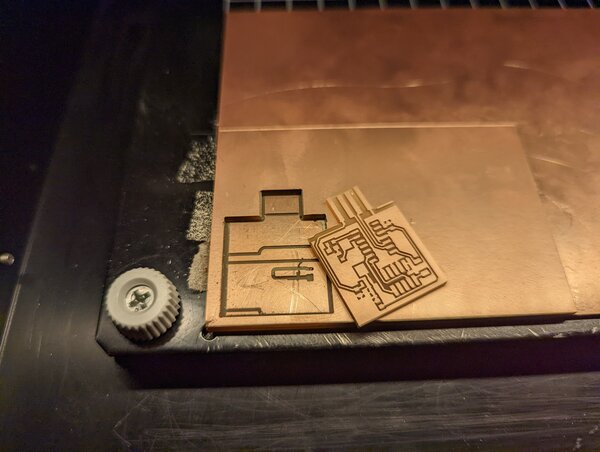
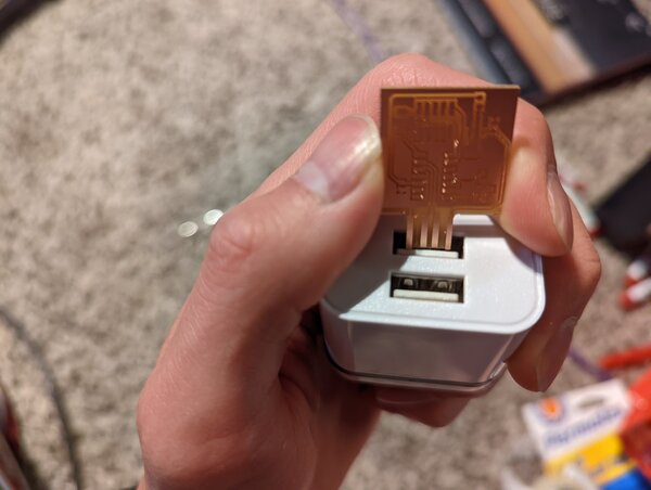
should’ve done some more homework before designing my usb footprint. pads line up fine, but definitely lacks the material required to align the usb in receptacle.
solder >
soldering mOnTaGe
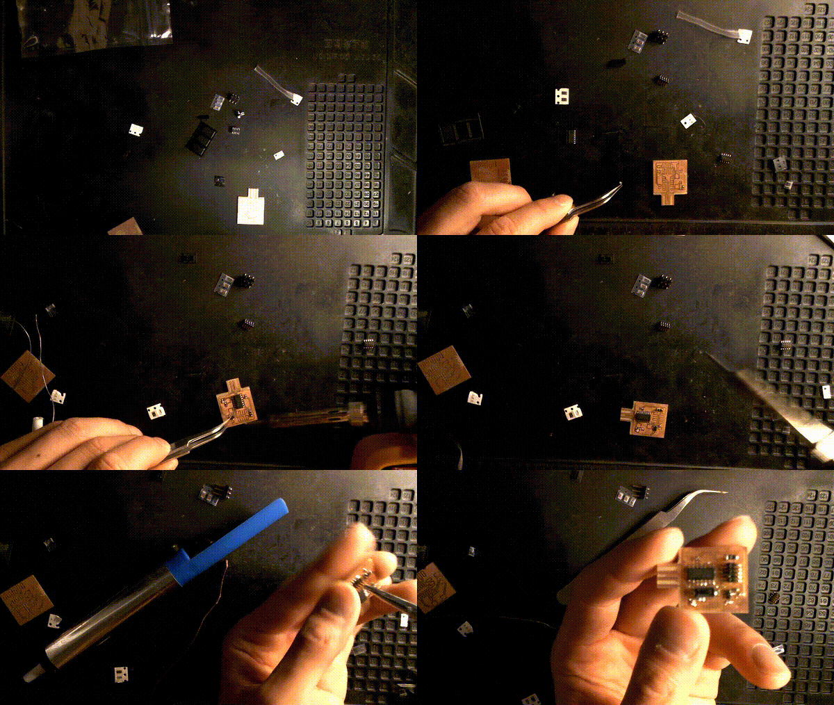
snags I had to resolve:
- I had a solderbridge that proved very difficult to remove
- tried solder sucker
- tried copper braid
- also used a toothpick and the soldering iron. no dice
- ultimately, clipped the pin because it wasn’t connected to anything, anyways.
- soldered Dan’s usb connector to my usb footprint, since it was mechanically too small
- checked diode orientation using multimeter
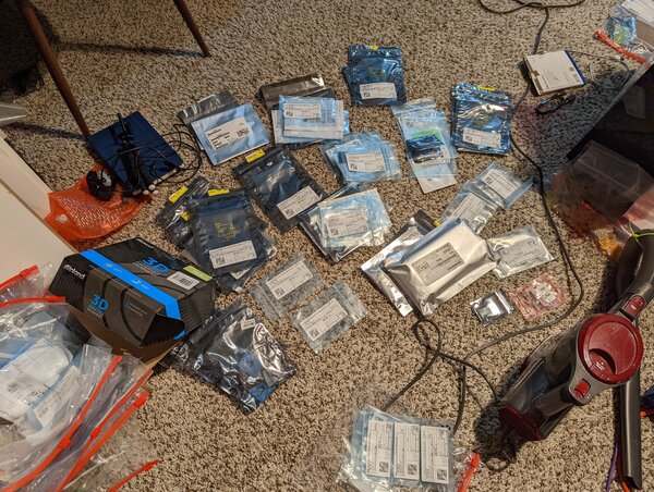
ran out of 1uF caps and went searching for a switch part way through my solderwork, ended up reorganizing some of my inventory.
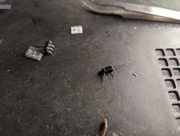
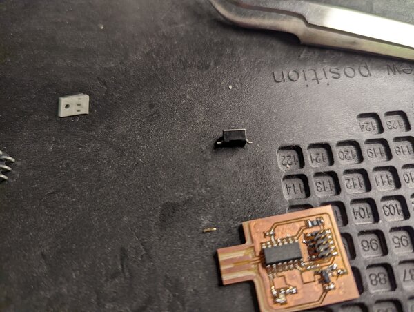
egads. turning a through hole switch into an SMT switch.
before:
 after:
hero shots >

breakout samd11c board >
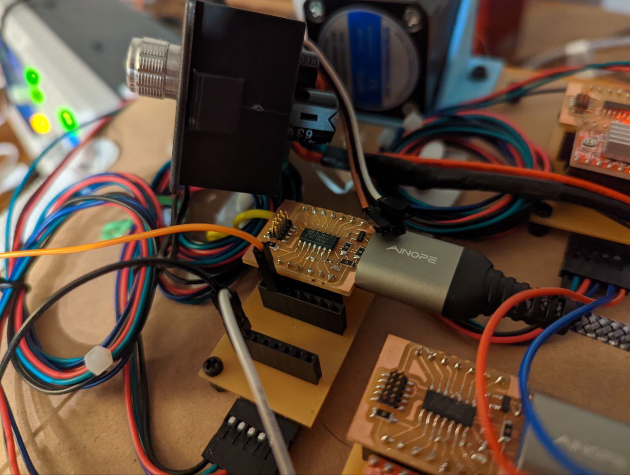
after multiple spirals iterating on urumbu boards, I made a further spiral of the samd11c as a breakout board since I found myself exposing different pins quite a bit after successive iterations.
to easily program the samd11c later without a programmer, a bootloader must be flashed. I document this further in week 8.
programming >
with the bootloader flashed, I upload blinky to demonstrate programming. I follow Quentin’s directions as specified here.
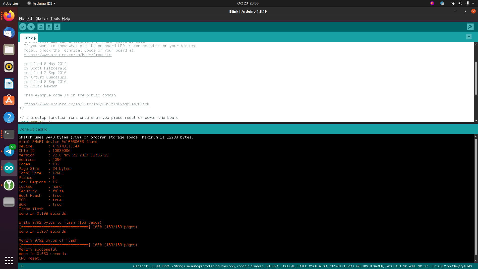
samd11c board w/ blinky flashing.