Output Devices
Assignment requirements:
Group Assignment
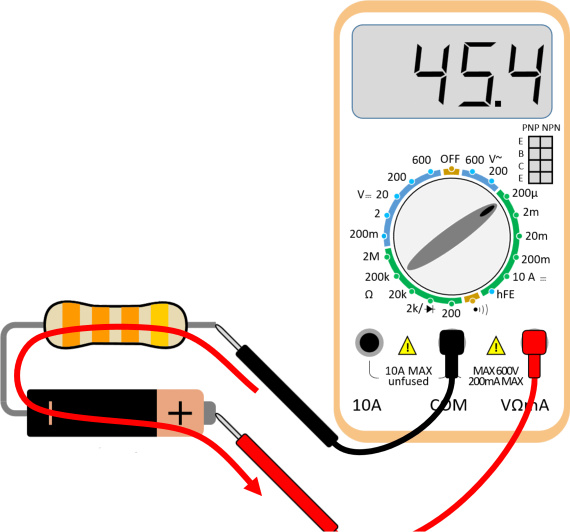
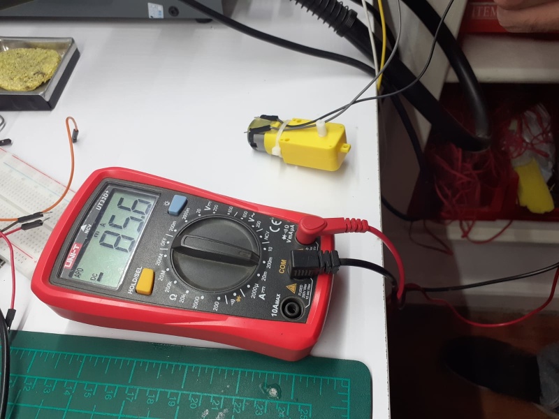
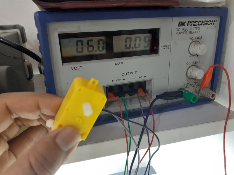
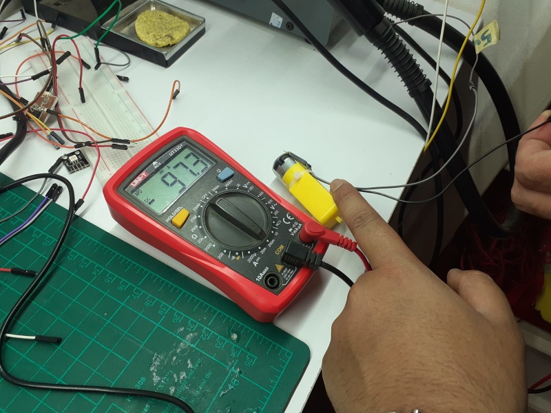
- easure the power consumption of an output device.
- Document your work (in a group or individually).
Individual Assignment
- Add an output device to a microcontroller board you've designed and program it to do something.
Learning outcomes:
- Demonstrate workflows used in controlling an output device(s) with MCU board you have designed.
Assessment criteria
- Linked to the group assignment page.
- Documented how you determined power consumption of an output device with your group.
- Documented what you learned from interfacing output device(s) to microcontroller and controlling the device(s).
- Describe your design and fabrication process or linked to previous examples.
- Explained the programming process/es you used.
- Outlined problems and how you fixed them.
- Included original design files and code
- Included a 'hero shot/video' of your board
Group Assignment
In this week we will learn more about output devices and how to measure the power consumption.
Individual Assignment
LED & Motor
                    /*
                      Fade

                      This example shows how to fade an LED on pin 9 using the analogWrite()
                      function.

                      The analogWrite() function uses PWM, so if you want to change the pin you're
                      using, be sure to use another PWM capable pin. On most Arduino, the PWM pins
                      are identified with a "~" sign, like ~3, ~5, ~6, ~9, ~10 and ~11.

                      This example code is in the public domain.

                      http://www.arduino.cc/en/Tutorial/Fade
                    */


                    int led = 10;           // the PWM pin the LED is attached to
                    int brightness = 0;    // how bright the LED is
                    int fadeAmount = 5;    // how many points to fade the LED by

                    // the setup routine runs once when you press reset:
                    void setup() {
                      // declare pin 9 to be an output:
                      pinMode(led, OUTPUT);
                    }

                    // the loop routine runs over and over again forever:
                    void loop() {
                      // set the brightness of pin 9:
                      analogWrite(led, brightness);

                      // change the brightness for next time through the loop:
                      brightness = brightness + fadeAmount;

                      // reverse the direction of the fading at the ends of the fade:
                      if (brightness <= 0 || brightness >= 255) {
                        fadeAmount = -fadeAmount;
                      }
                      // wait for 30 milliseconds to see the dimming effect
                      delay(100);
                    }
Speaker
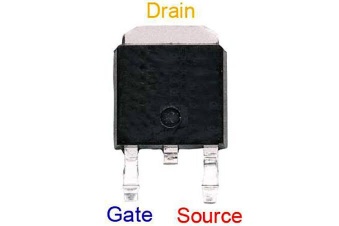
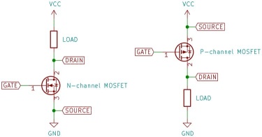
                    #define MOSFET_pin (1 << PA7)
                    #define MOSFET_port PORTA
                    #define MOSFET_direction DDRA
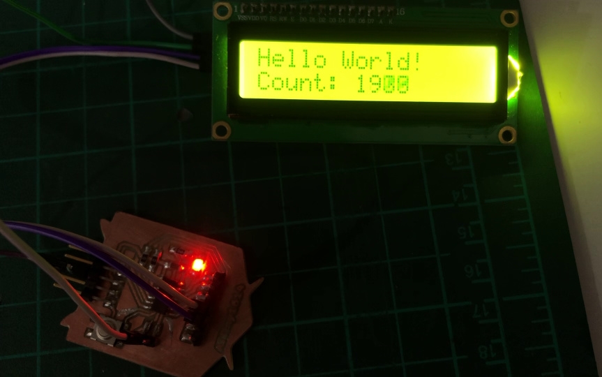
LCD