
Week 5
3D Scanning and Printing
This week we are designing, 3D printing, and 3D scanning some cool stuff.
- Group Assignment.
- Test the design rules for our 3D printer(s).
- Individual Assignment
- Design and 3D print an object (small, few cm3, limited by printer time) that could not be made subtractively.
- 3D scan an object (and optionally print it).
Intro
Difference between Additive and Subtractive manufacturing
Additive manufacturing is a process that adds successive layers of material to create an object, often referred to as 3D printing. Subtractive manufacturing, as the name suggests, is the opposite.
A. Additive manufacturing
Additive manufacturing allows for the creation of objects with precise geometric shapes. These are built layer by layer, as with a 3D printing process, which is in contrast to traditional manufacturing that often requires machining or other techniques to remove surplus material.
3D printing a model at Fab Lab Egypt
B. Subtractive manufacturing
Subtractive manufacturing is a process by which 3D objects are constructed by successively cutting material away from a solid block of material. Subtractive manufacturing can be done by manually cutting the material but is most typically done with a CNC Machine as we made last week in Week 4 when we managed to mill our PCB.
CNC milling machine
Resources: Creative Mechanisms, AutoDesk, TWI,
Group Assignment
In this assignment we need to test the design rules for our 3D printers: overhang, clearance, tolerance, bridging, wall thickness, dimensions, surface finish, etc...Here at Fab Lab Egypt we have Prusa i3 MK3S+ and Prusa i3 MK2S 3D printer machines, so we decided to characterize both machines.
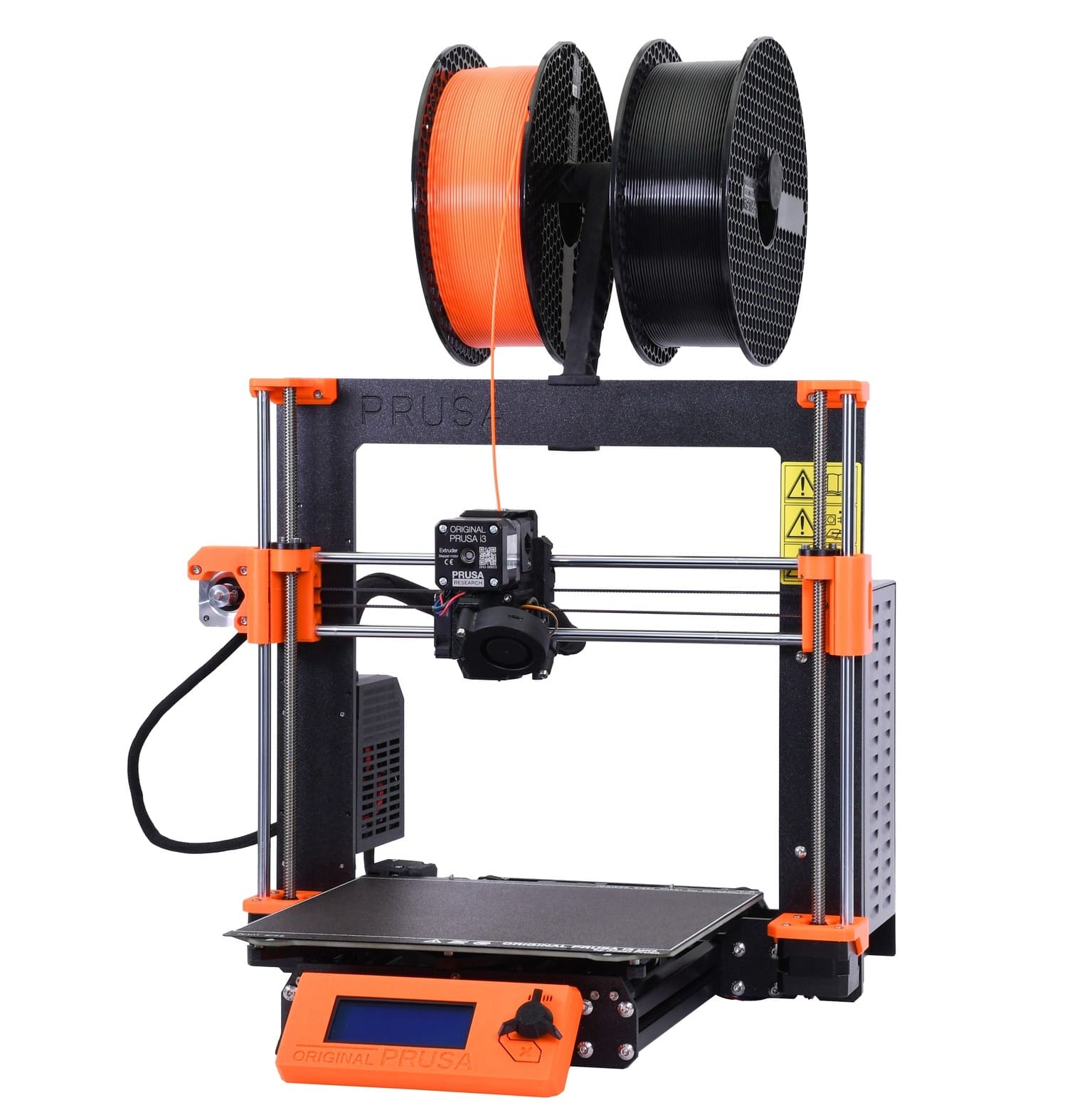
i3 MK3S+ i3 MK2S
So we started by the characteristics of the 3D printers we have and measuring and calculating the design rules.
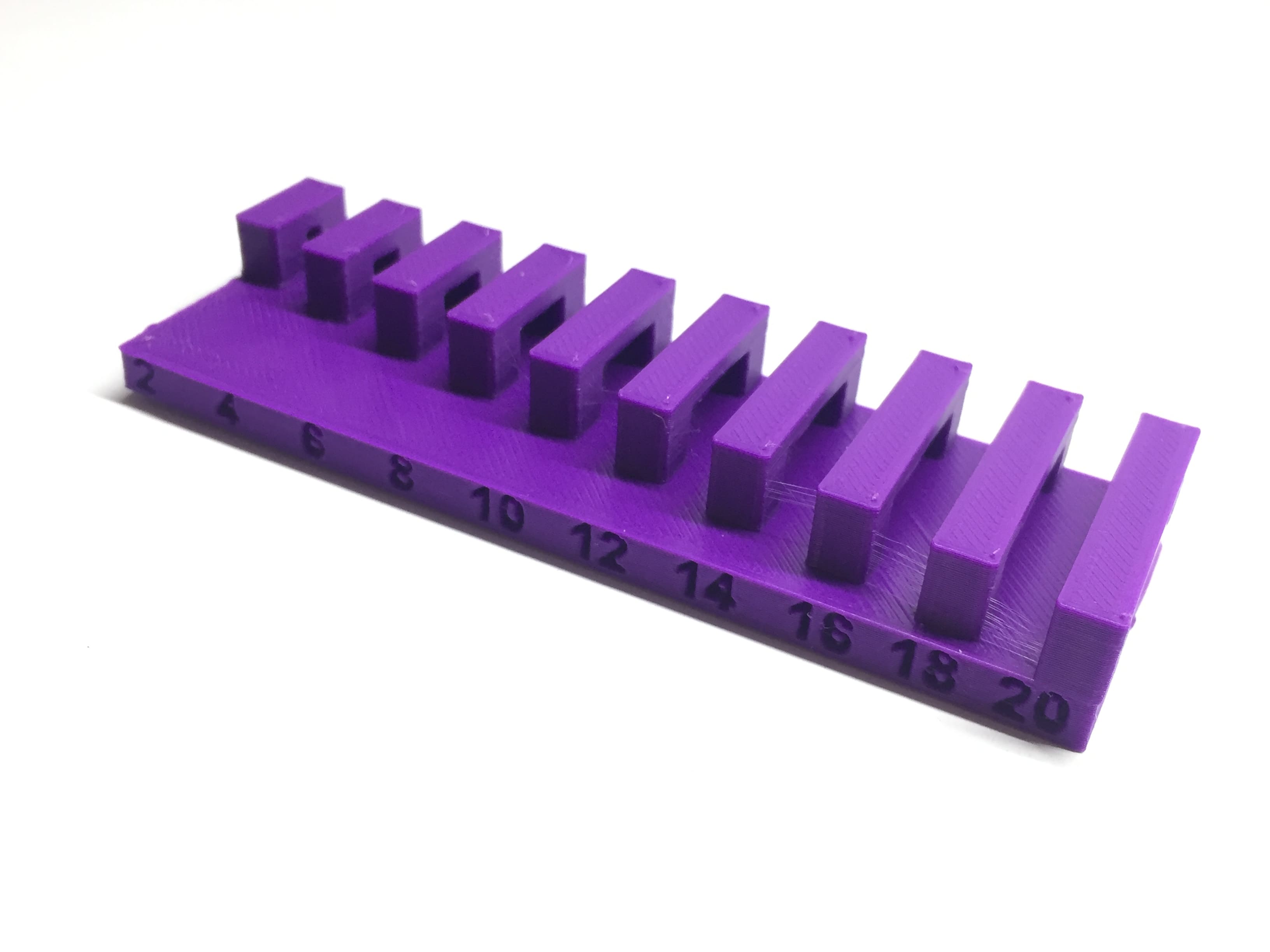
Tolerance
We printer a very famous design for measuring the tolerance of the machine that has a clearance from 0.1mm till 1mm.
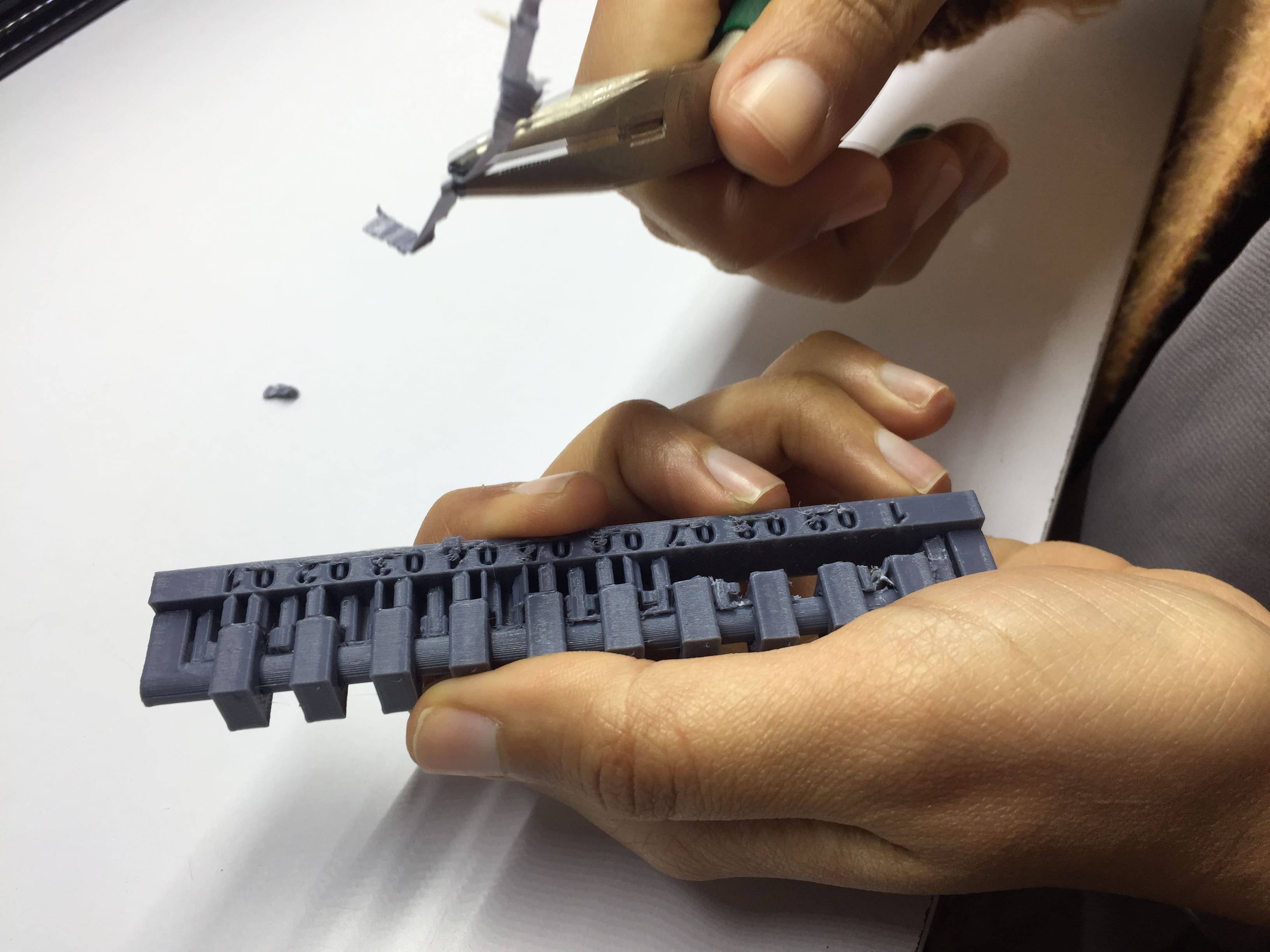
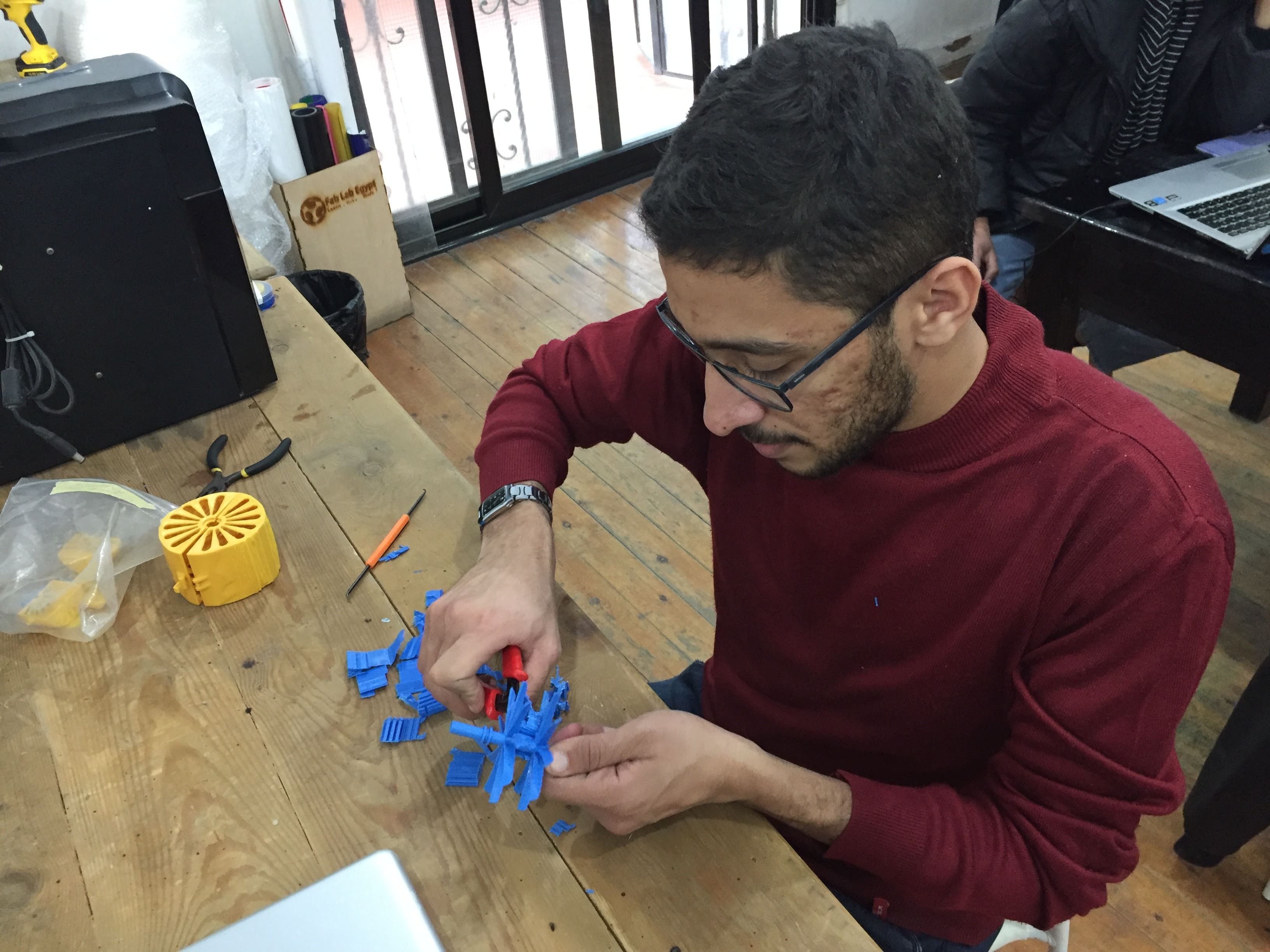
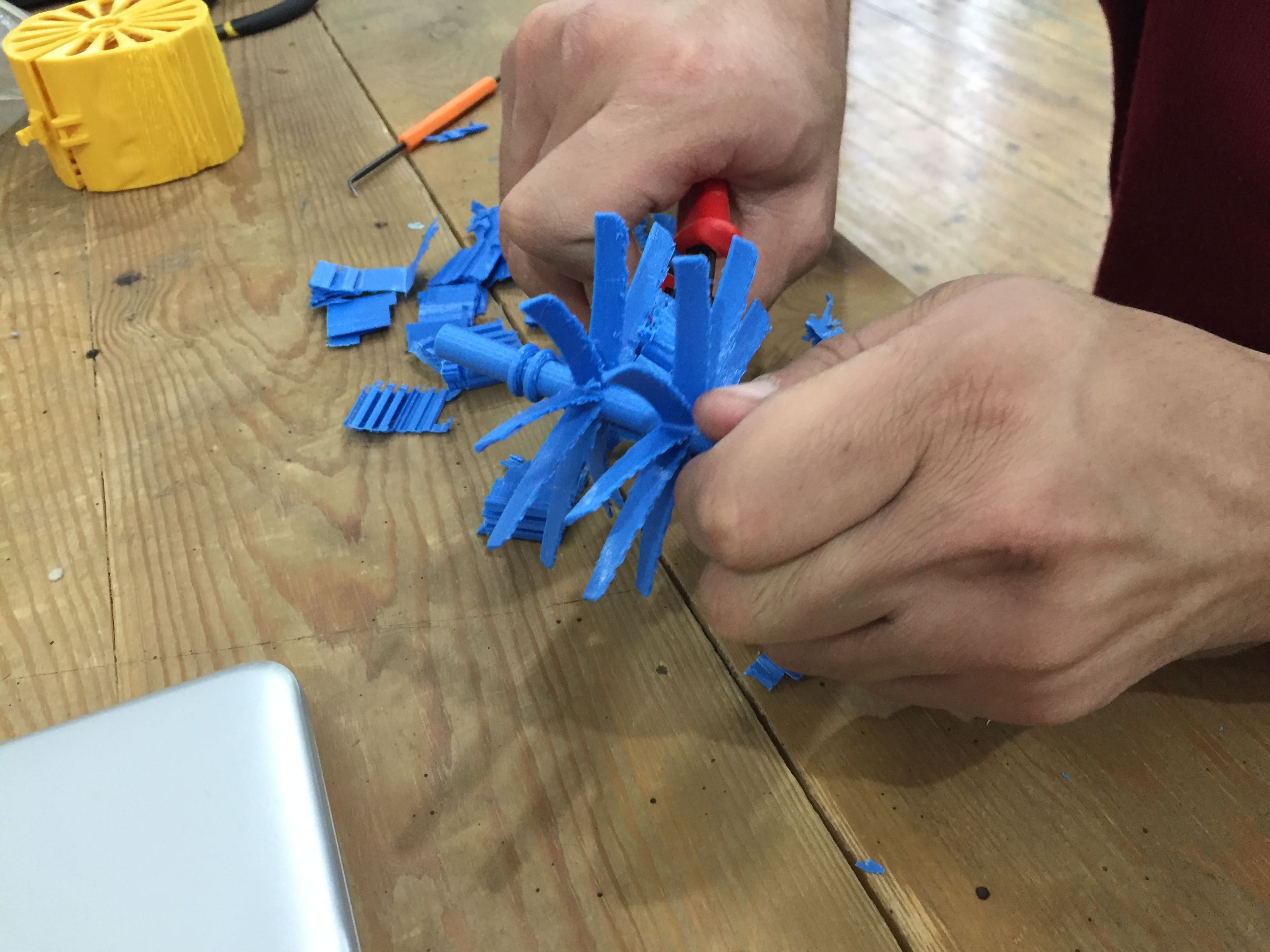
Removing Support
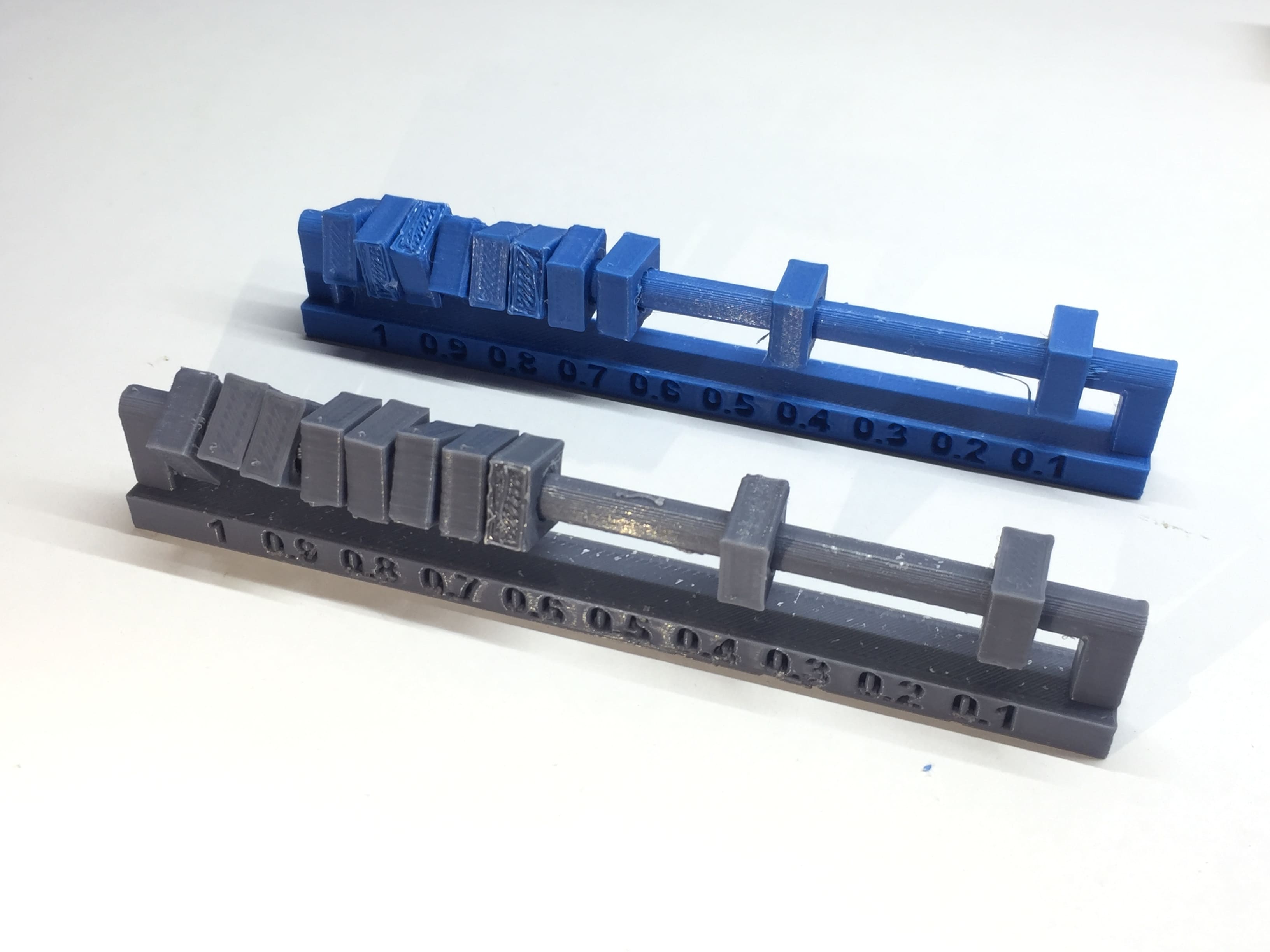
Tolerance test
And we concluded from that test that the minimum tolerance between two parts that need to moving is 0.2mm.
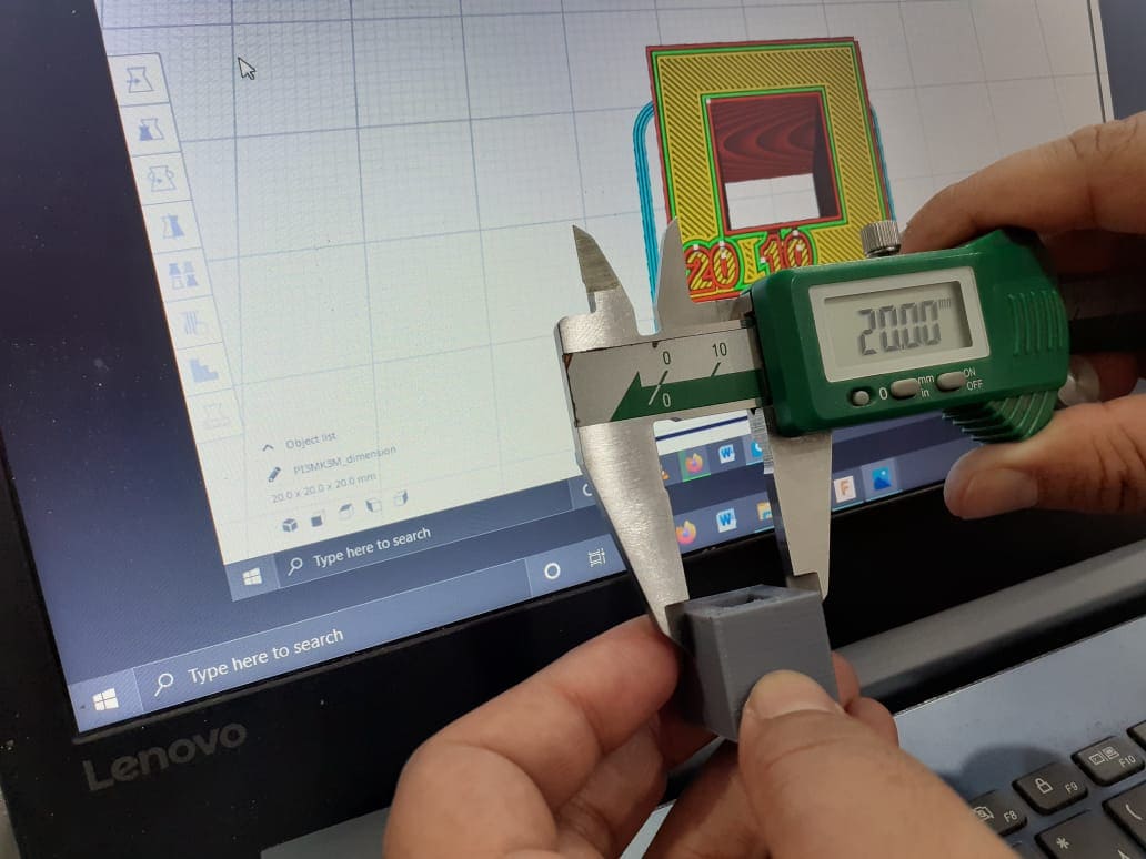
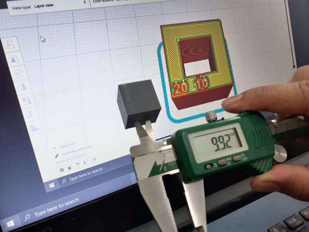
Dimensions
The next test is the dimensions test, and here we printed a cube with 20mm in length and width and having a square hole inside with 10mm in length and width.
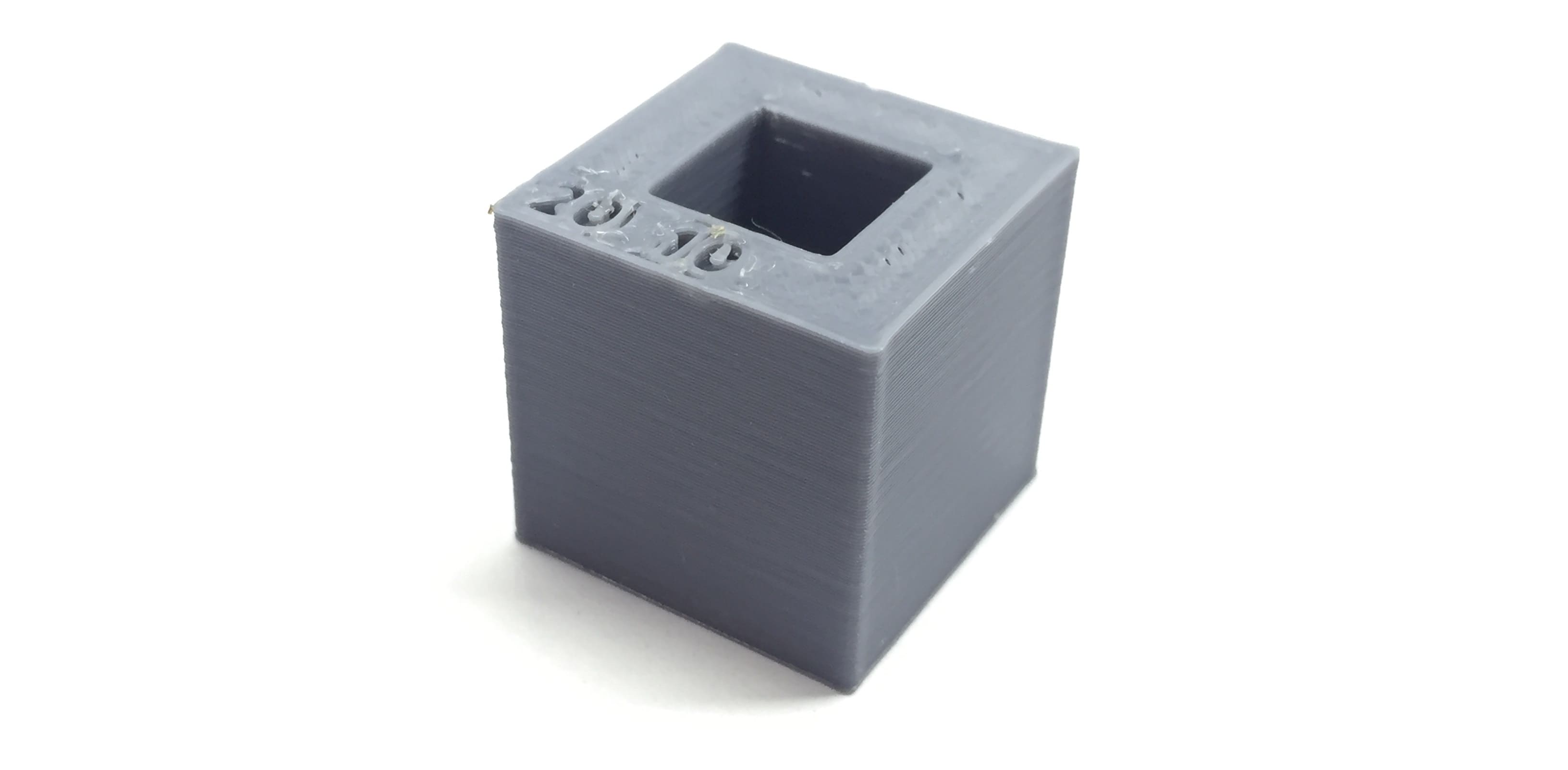
Dimensions test box
And after calculating the dimensions with a Vernier calliper we found that the outer dimensions where perfect and was 20mm exactly but the inner were less that the design as the hole was 9.92mm instead of 10mm.
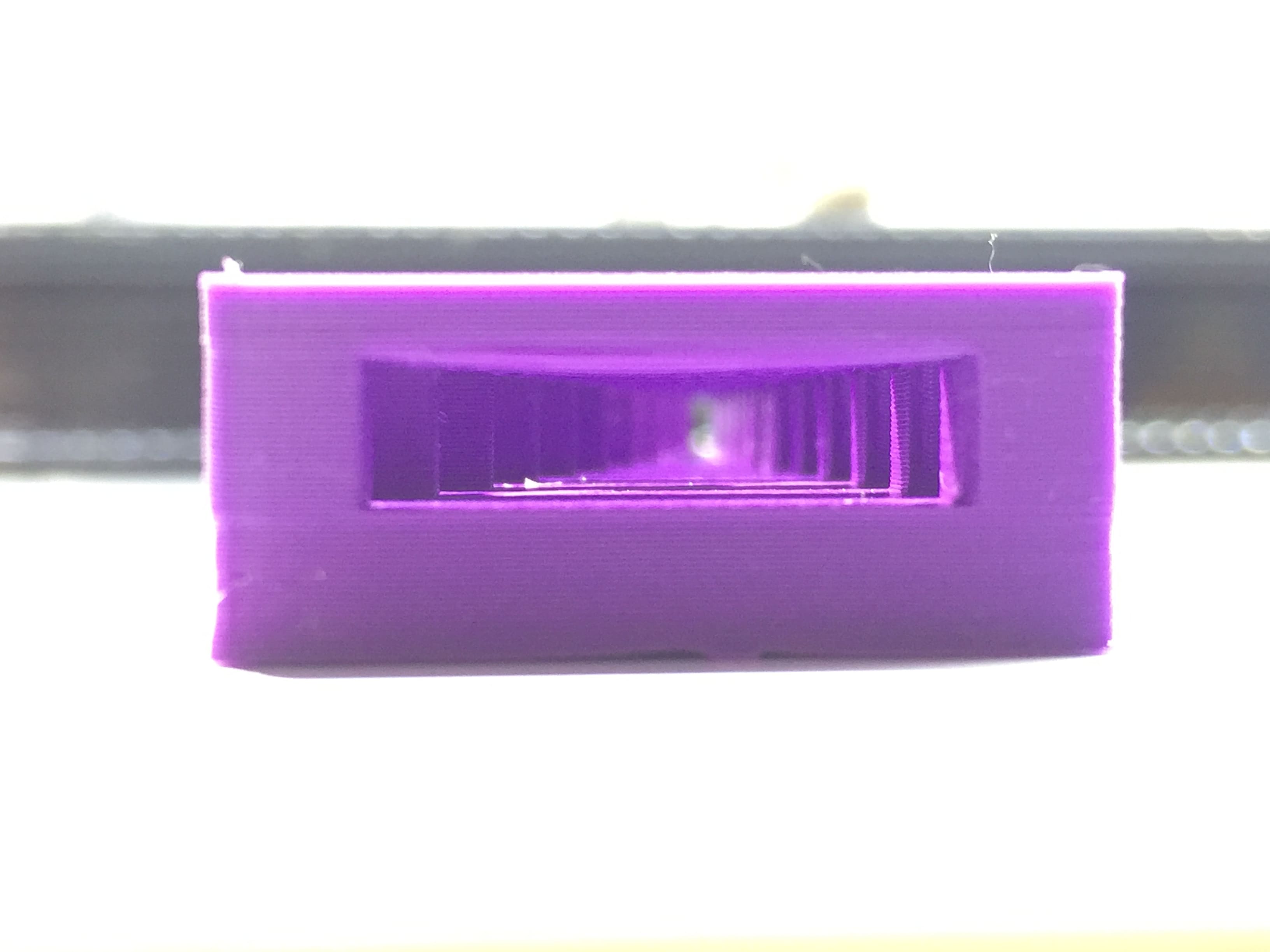
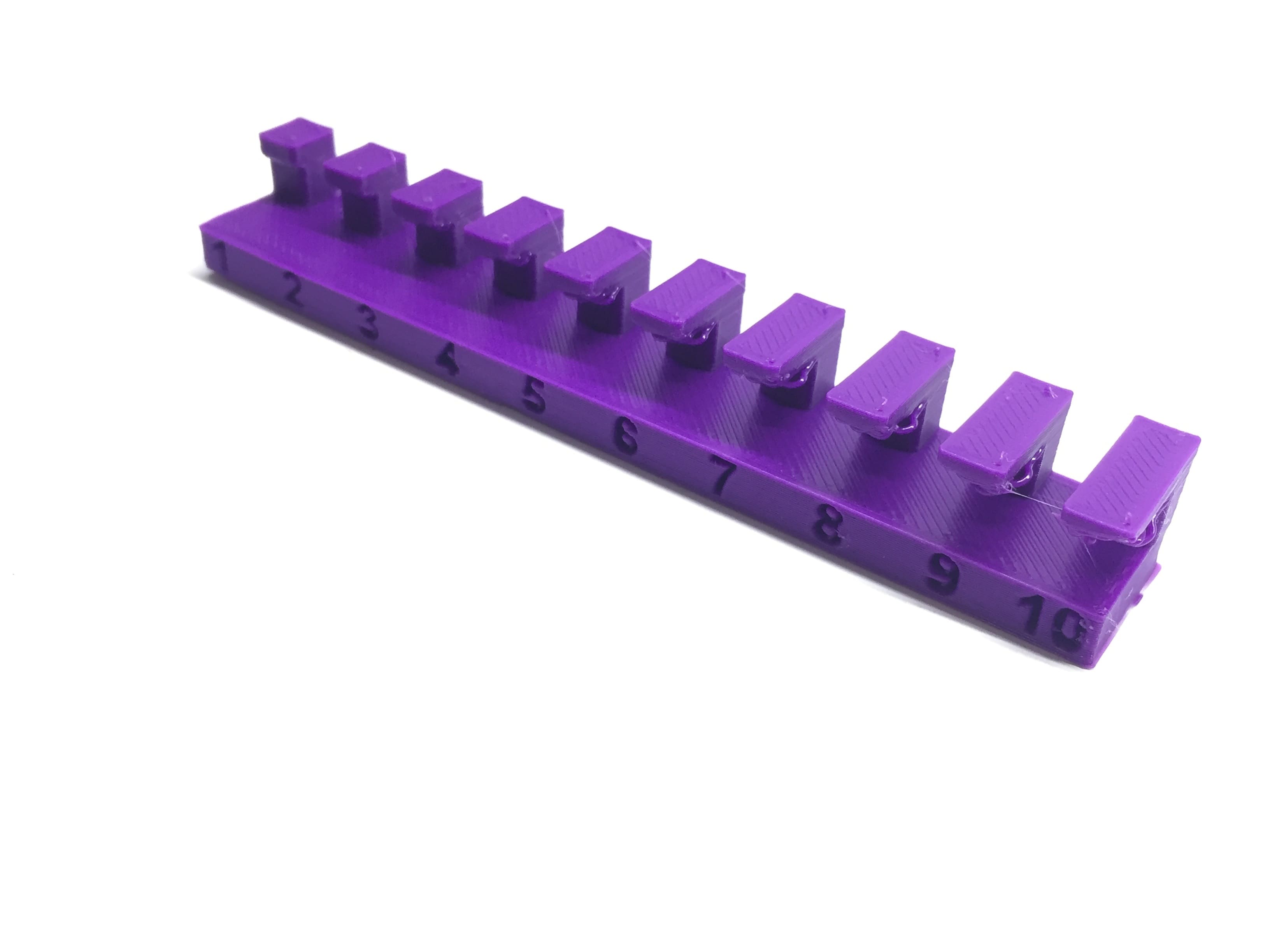
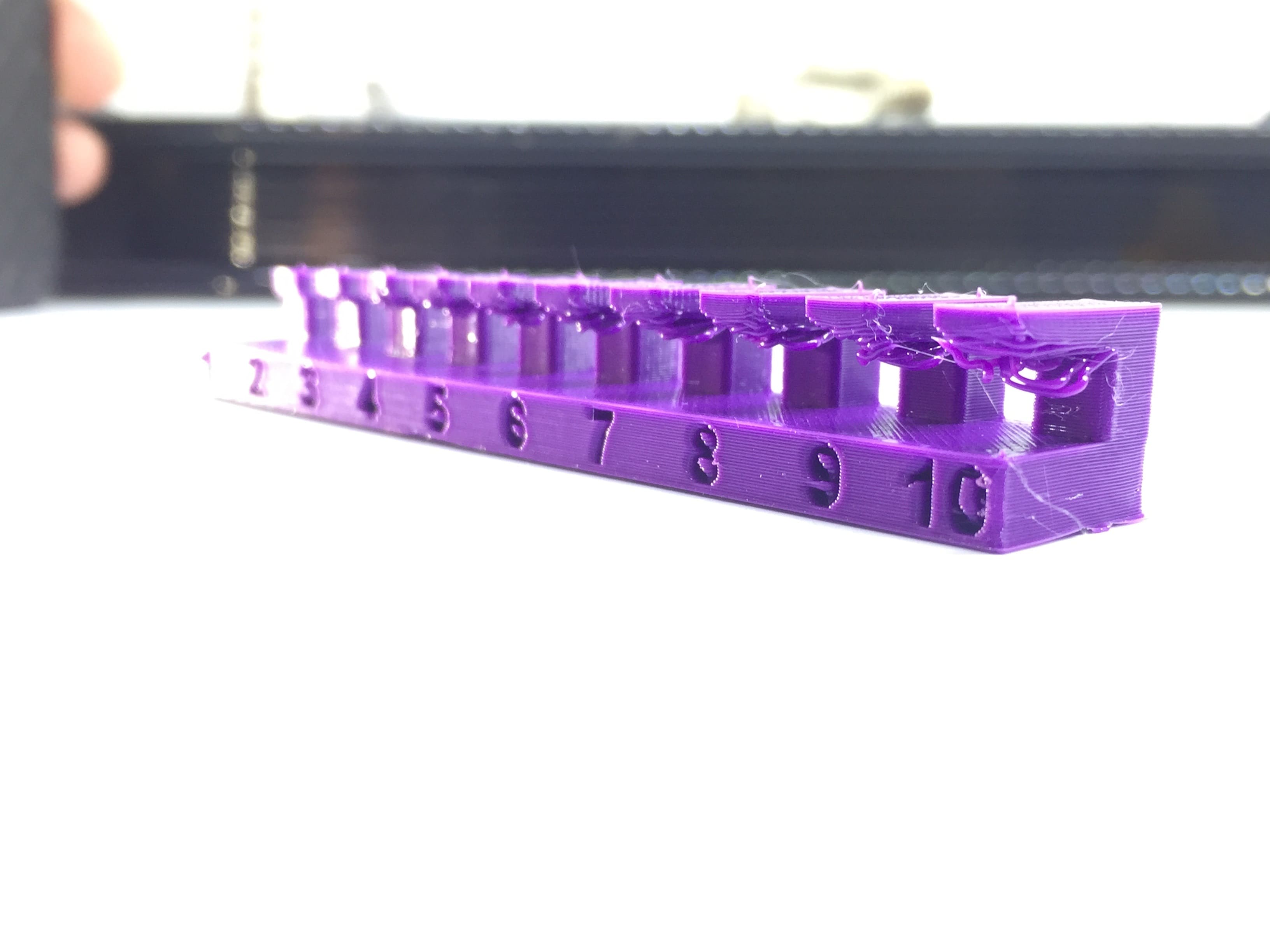
Bridging
Testing the bridging came out perfectly as although the longest bridge between two vertical columns was 20mm long but it was printed without deformations.
Finish
Here we are testing the difference between layer heights so we printed the same part with 0.1mm and 0.2mm layer height.
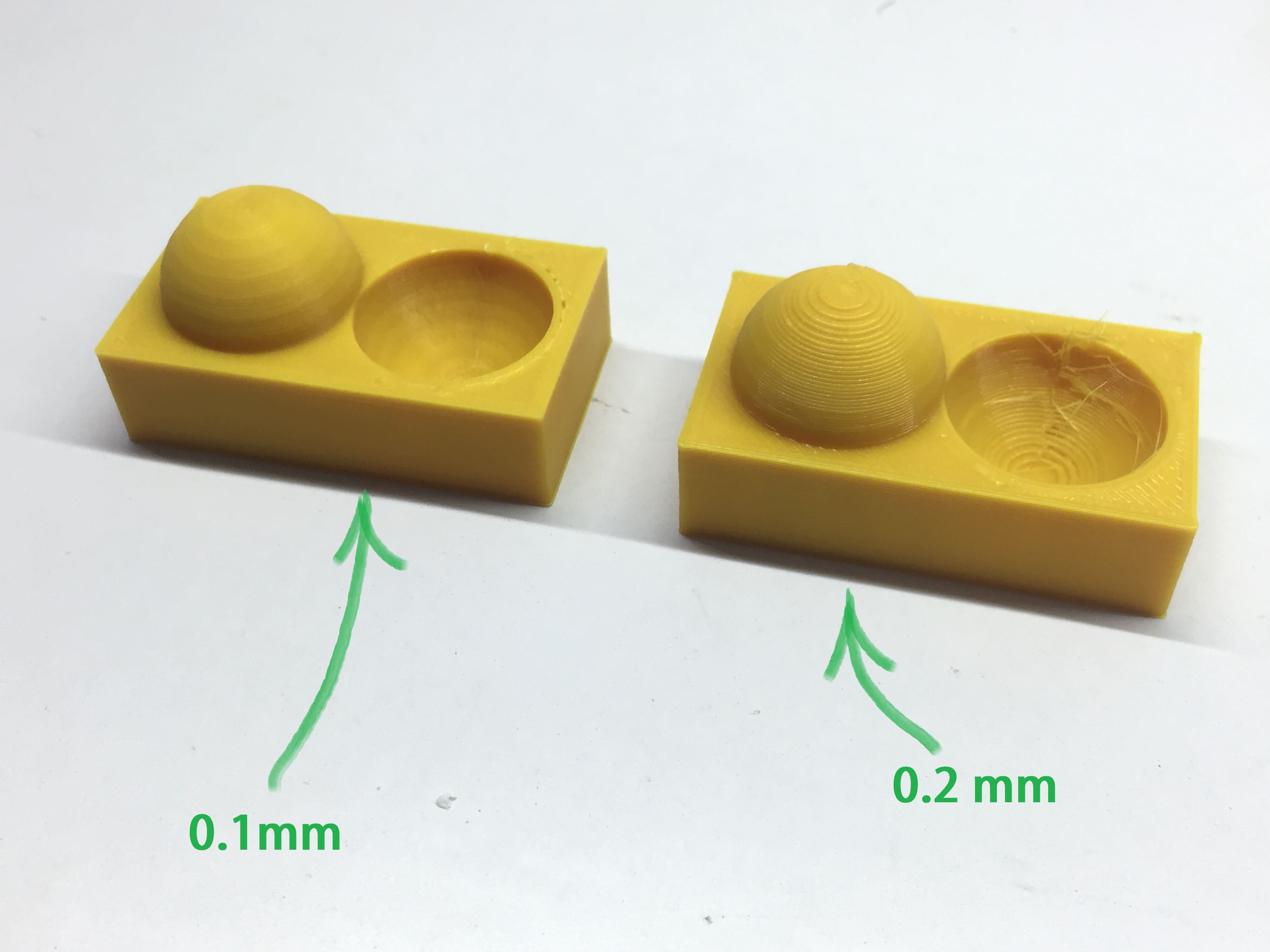
Difference between 0.1mm and 0.2mm layer height
Overhang
The overhang test wasn't as expected as the longest distance came out printed good enough was around 3mm which seemed very short.
Overhang test
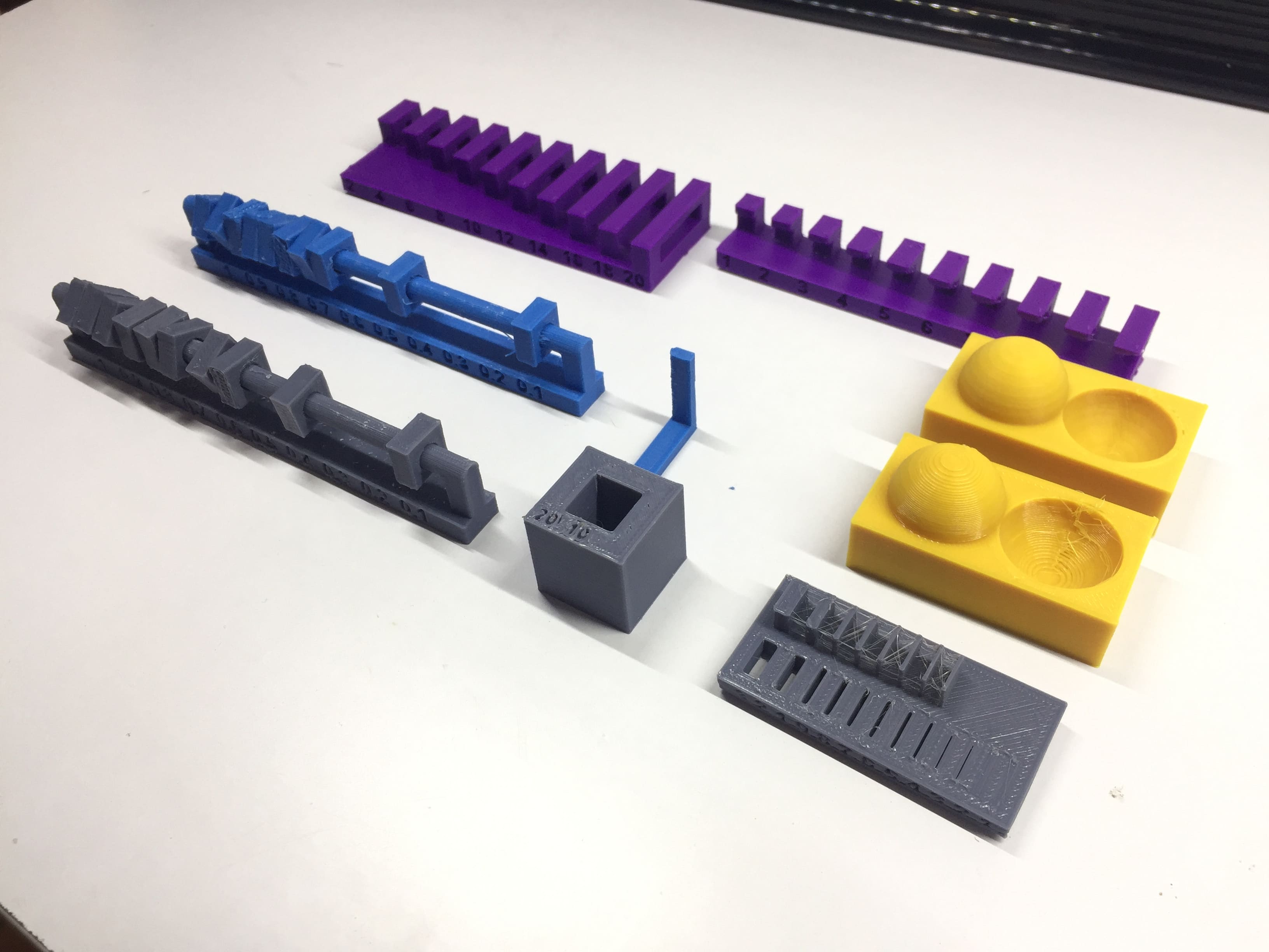
And here we see all the tests we made for two of our 3D printers.
Individual Assignment
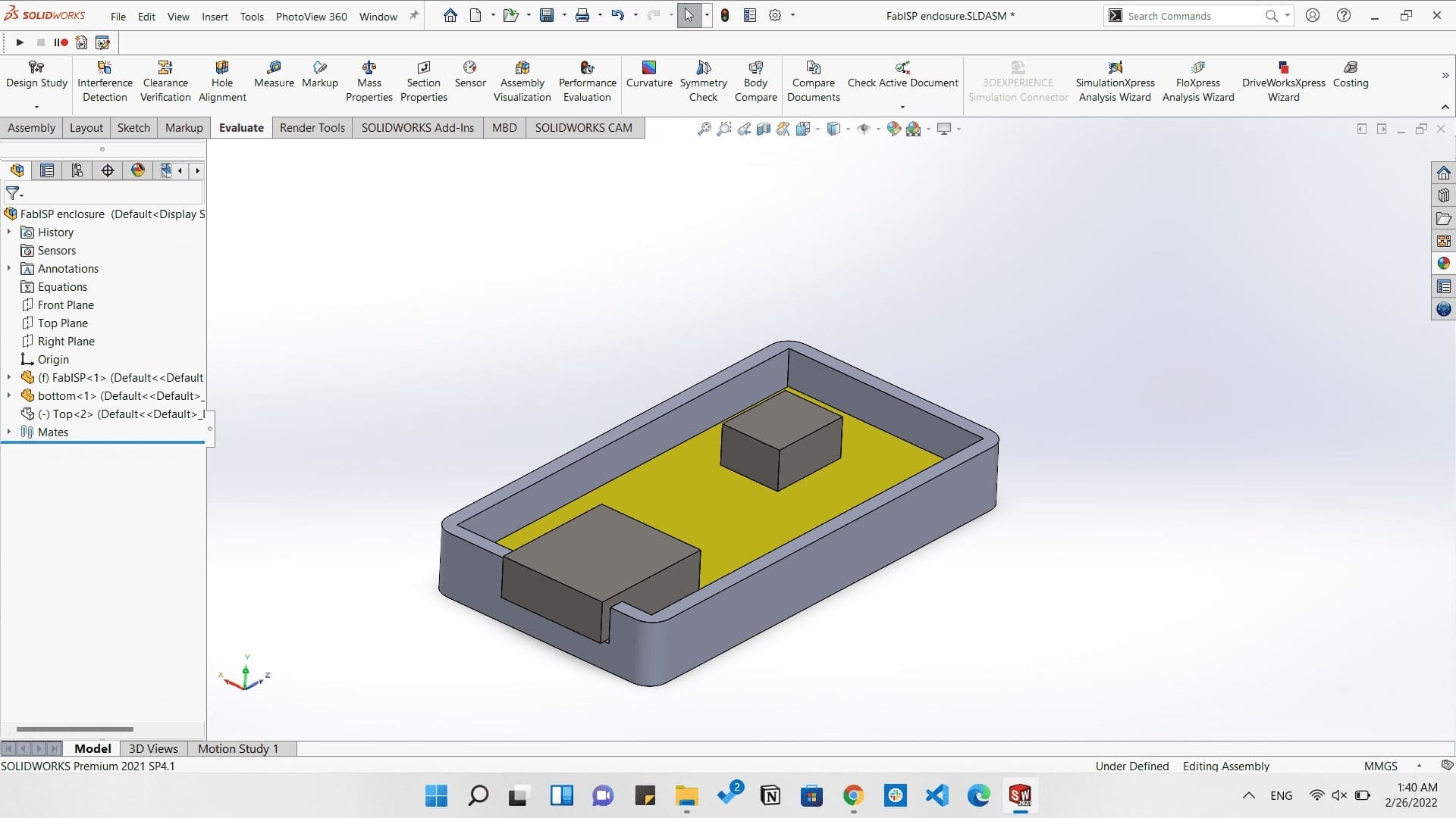
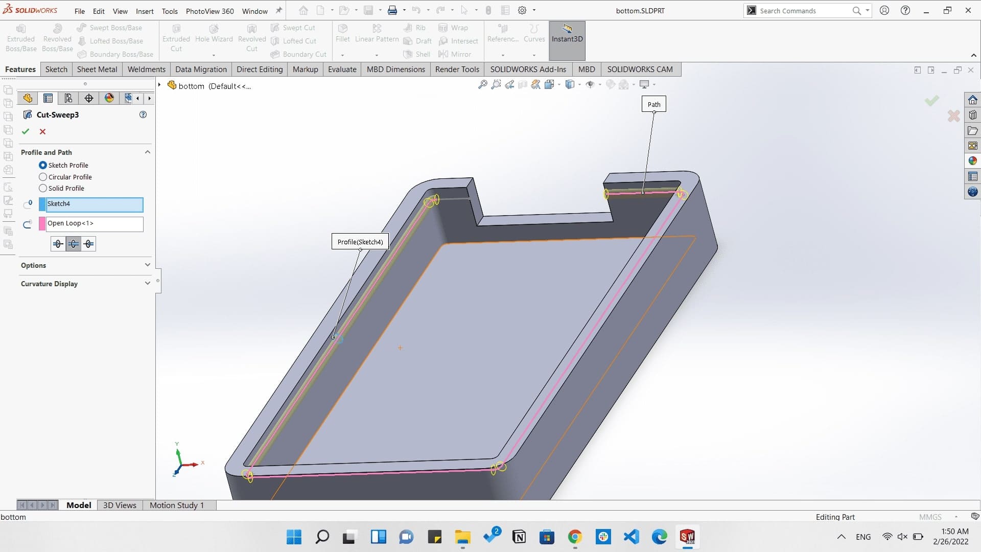
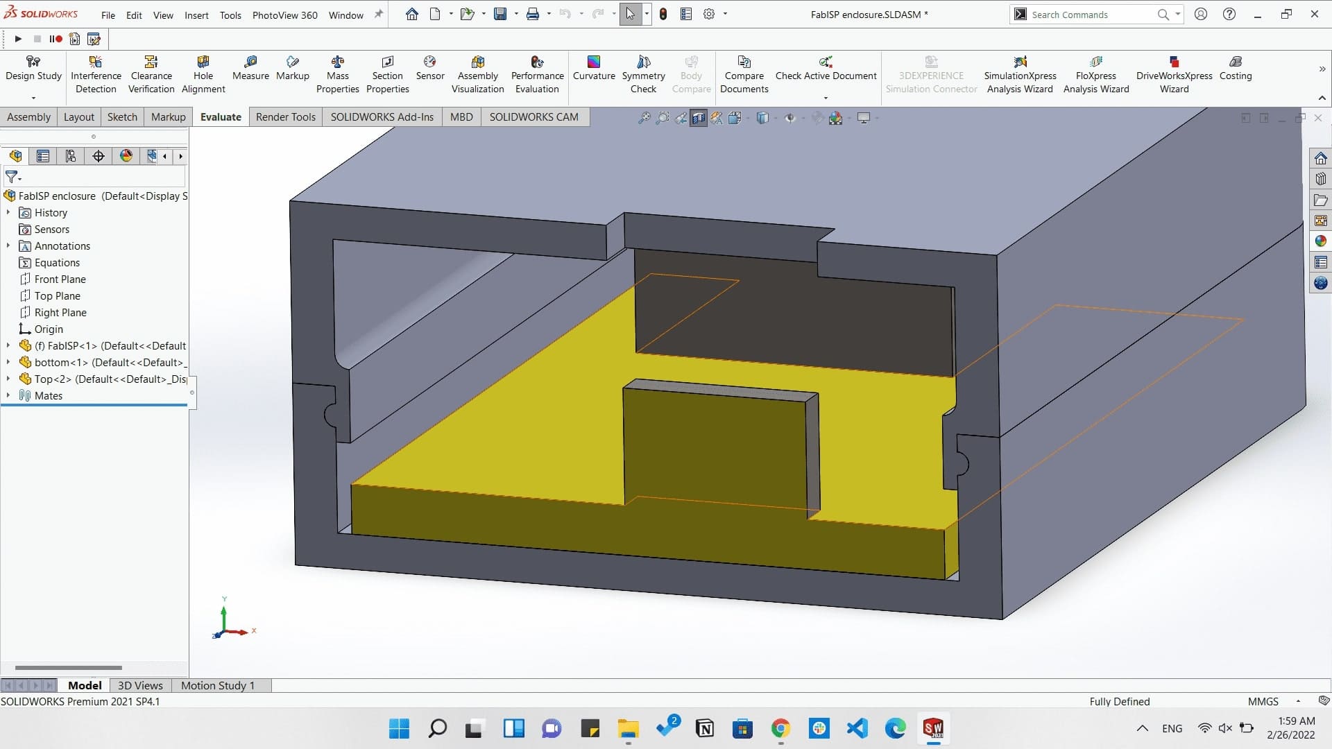
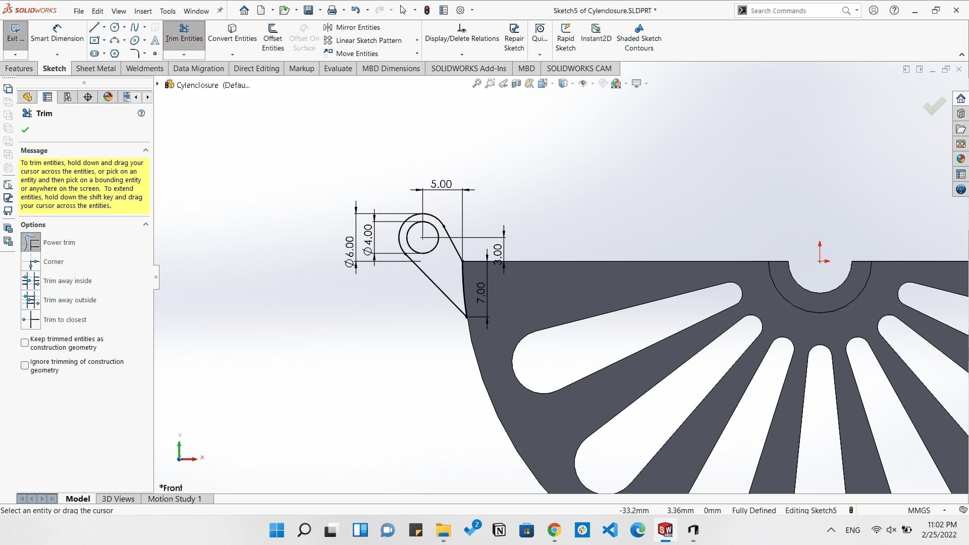
As the assignment requires, we need to to design and 3D print something that can not be subtractively manufactured easily. So I started by an exercise for making an enclosure for the FabISP board I made last week, and make the fits according to the characteristics we made.
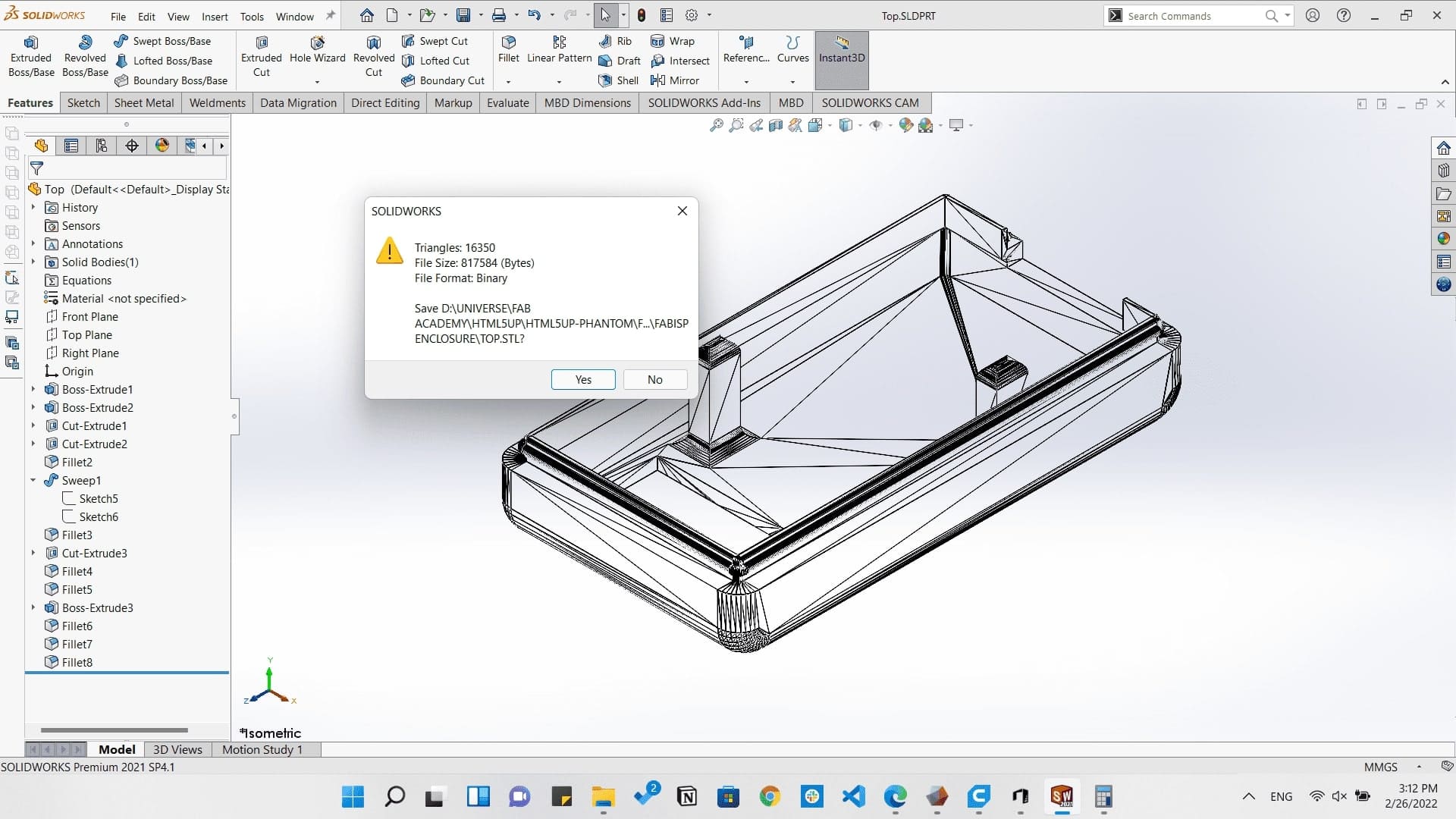
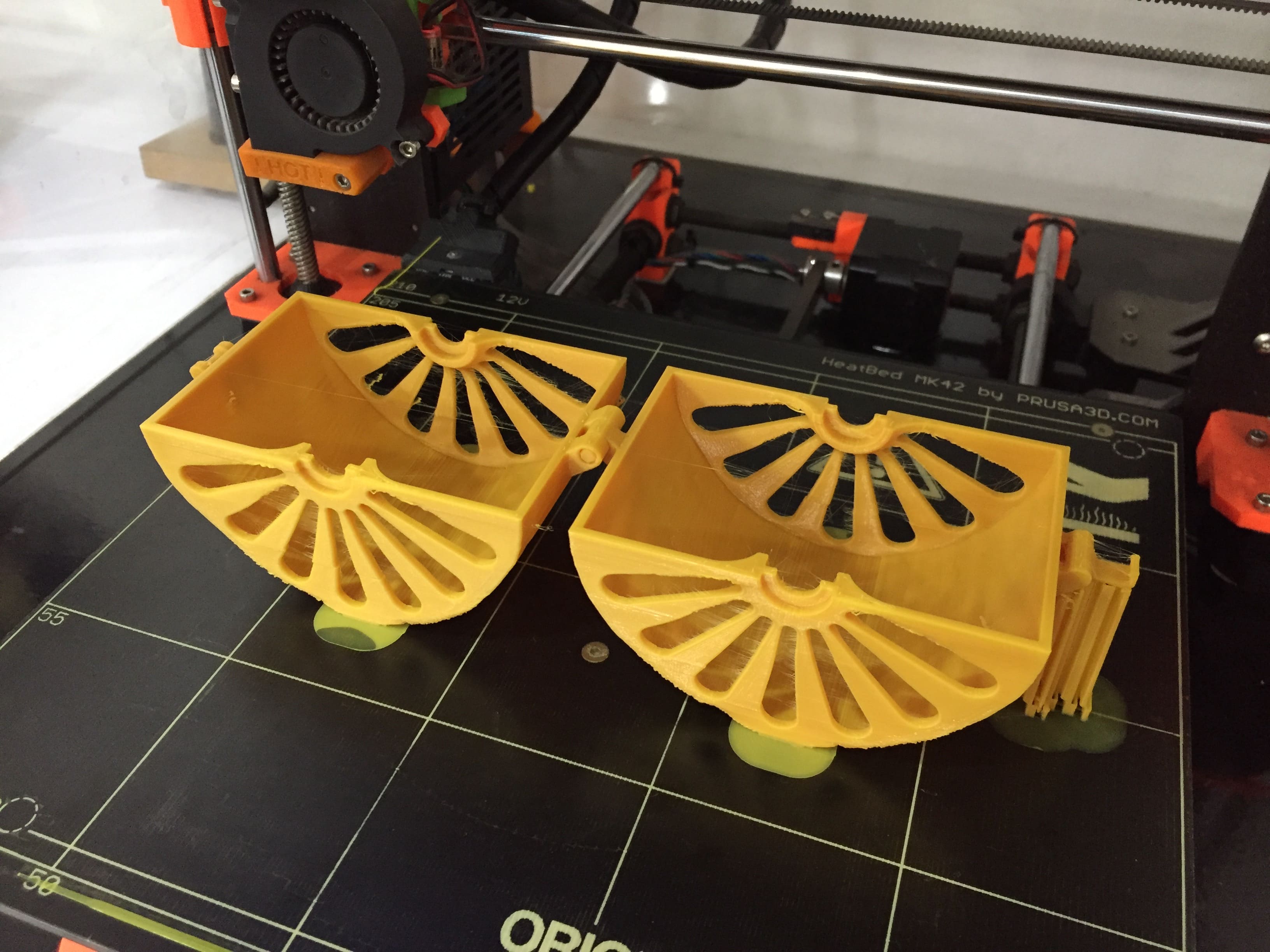
Then I started 3D printing it
ISP enclosure printing
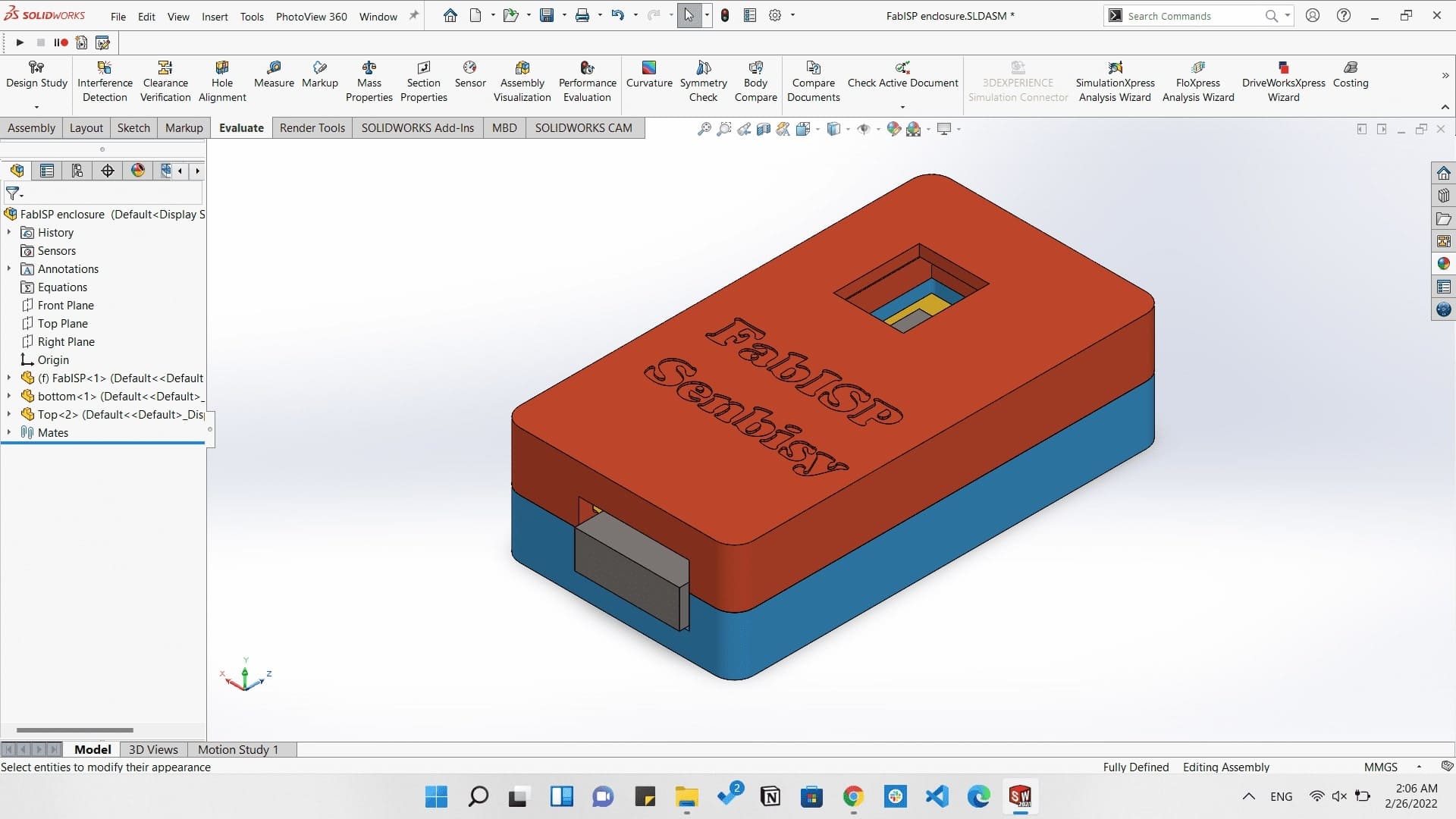
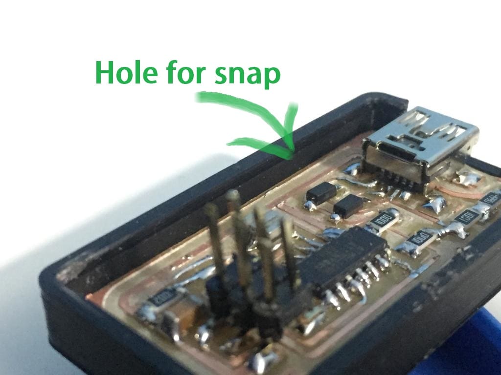
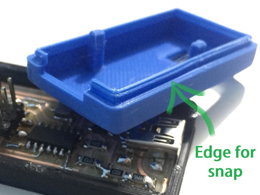
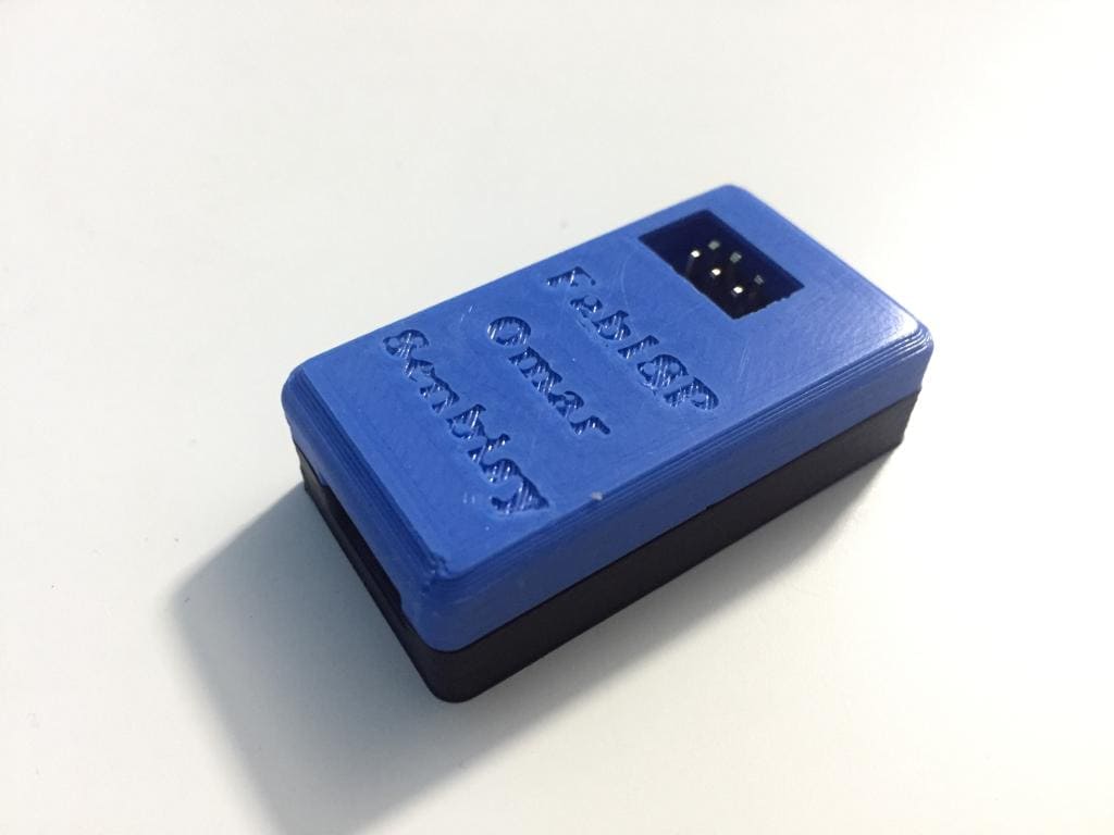
And this is how it came out...
ISP enclosure assembly
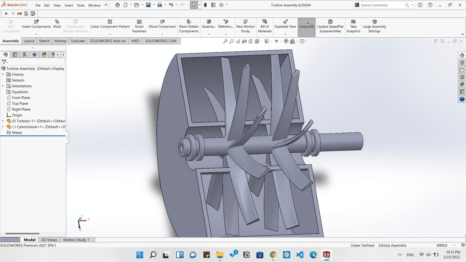
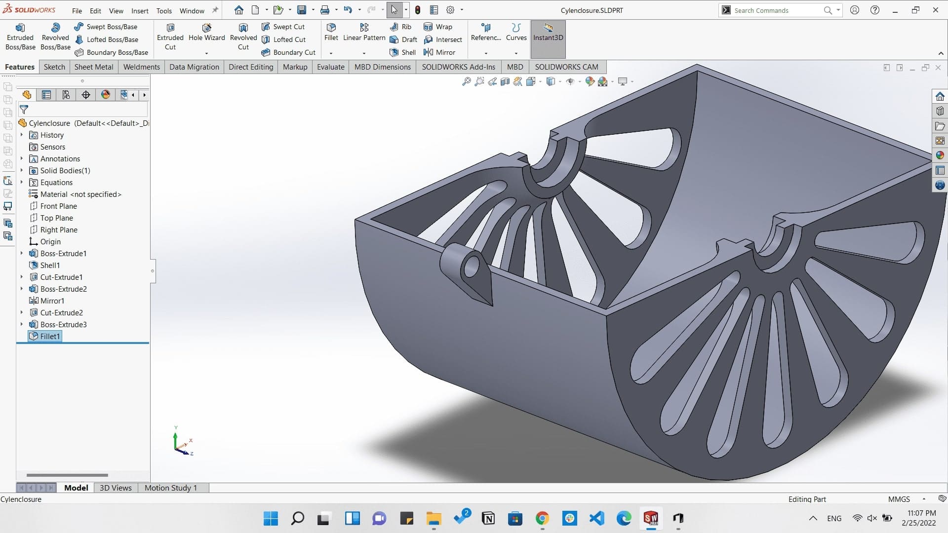
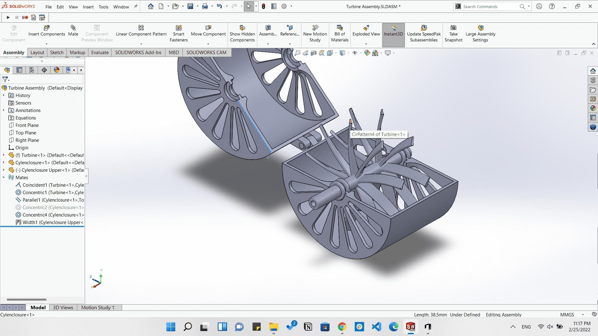
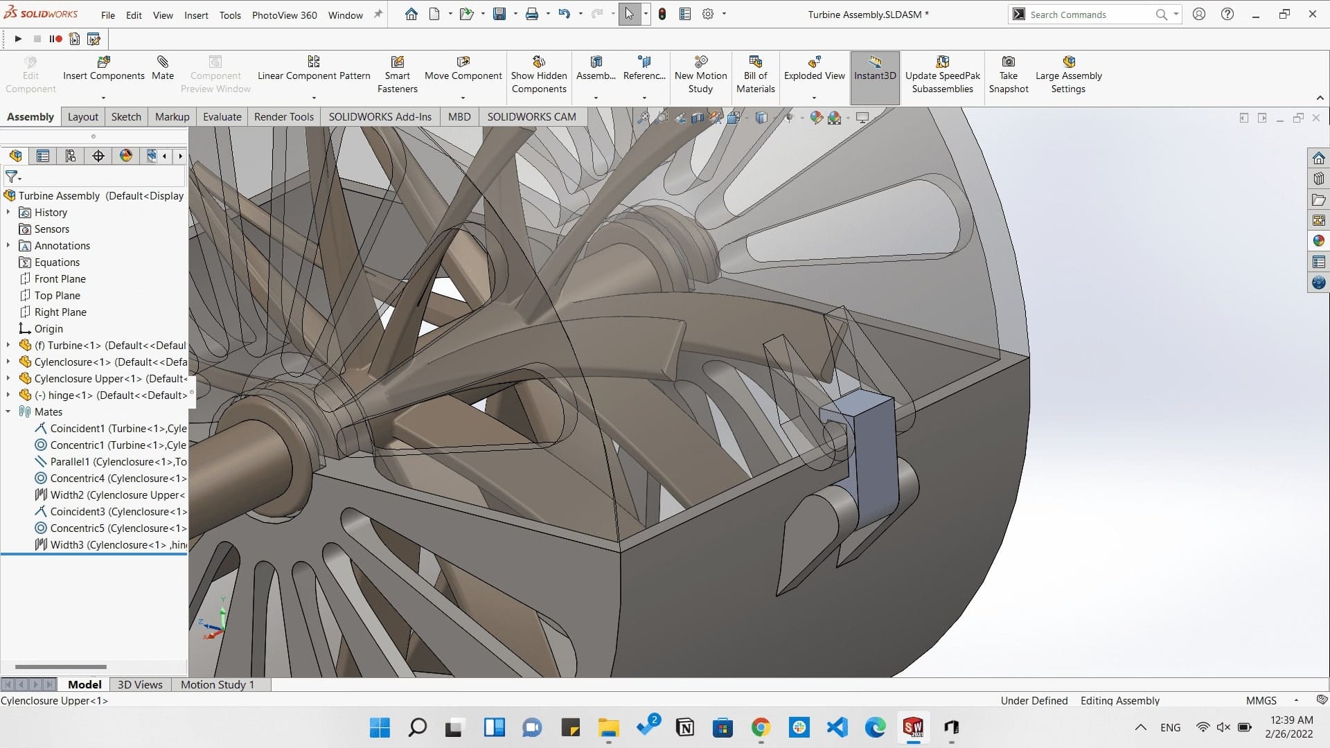
Here I wanted to make something that can't be easily made by subtractive machining, and I always adored Jet engines so I decided to design an Air turbine with an enclosure.

Omar inside a jet engine:)
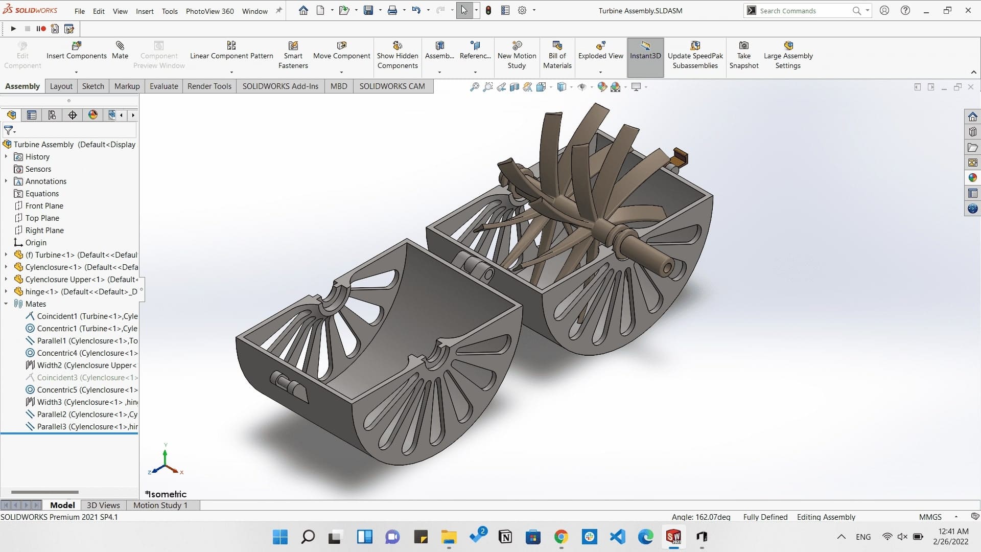
So by using SolidWorks I started making the blades and the rotor.
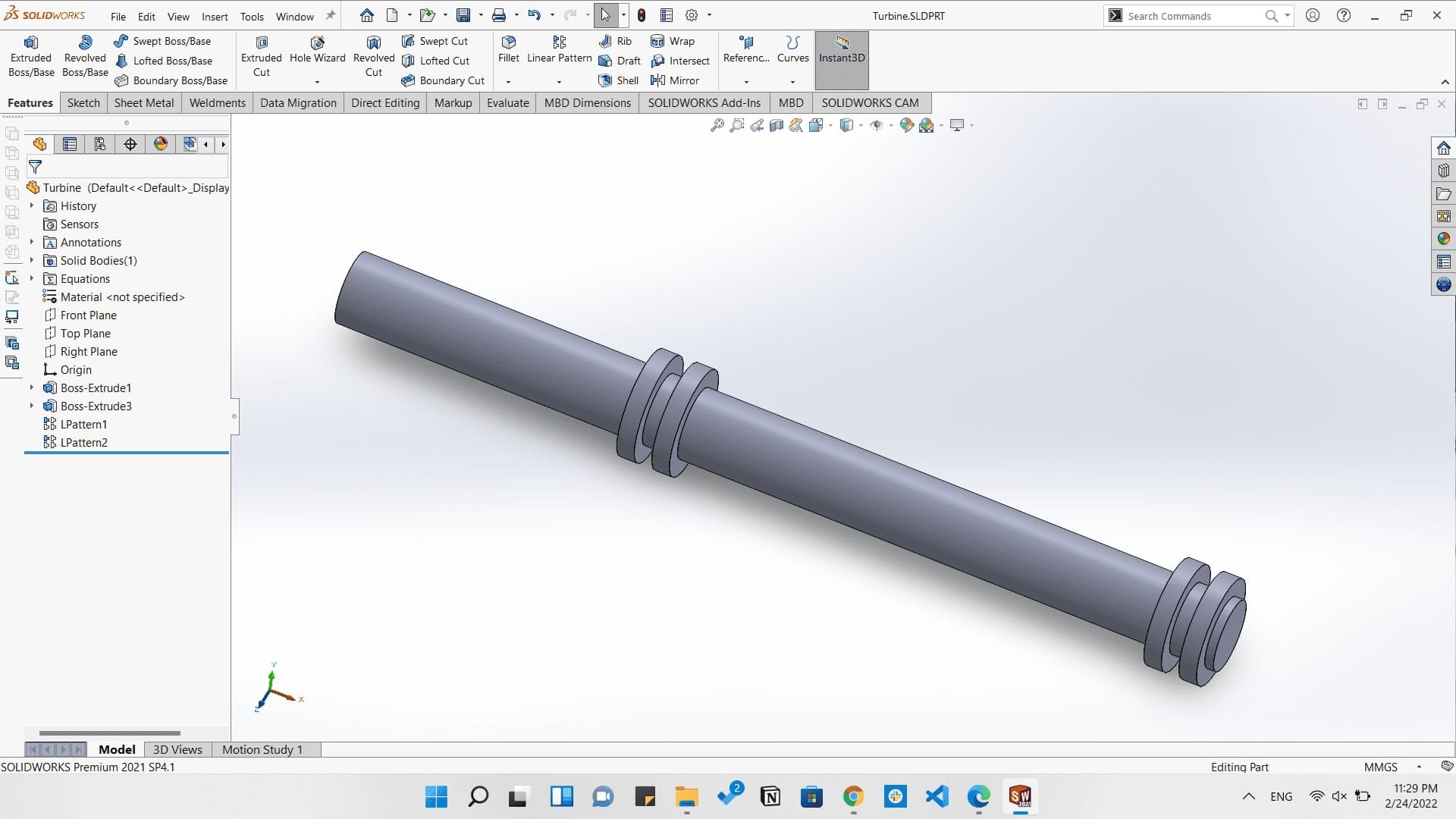
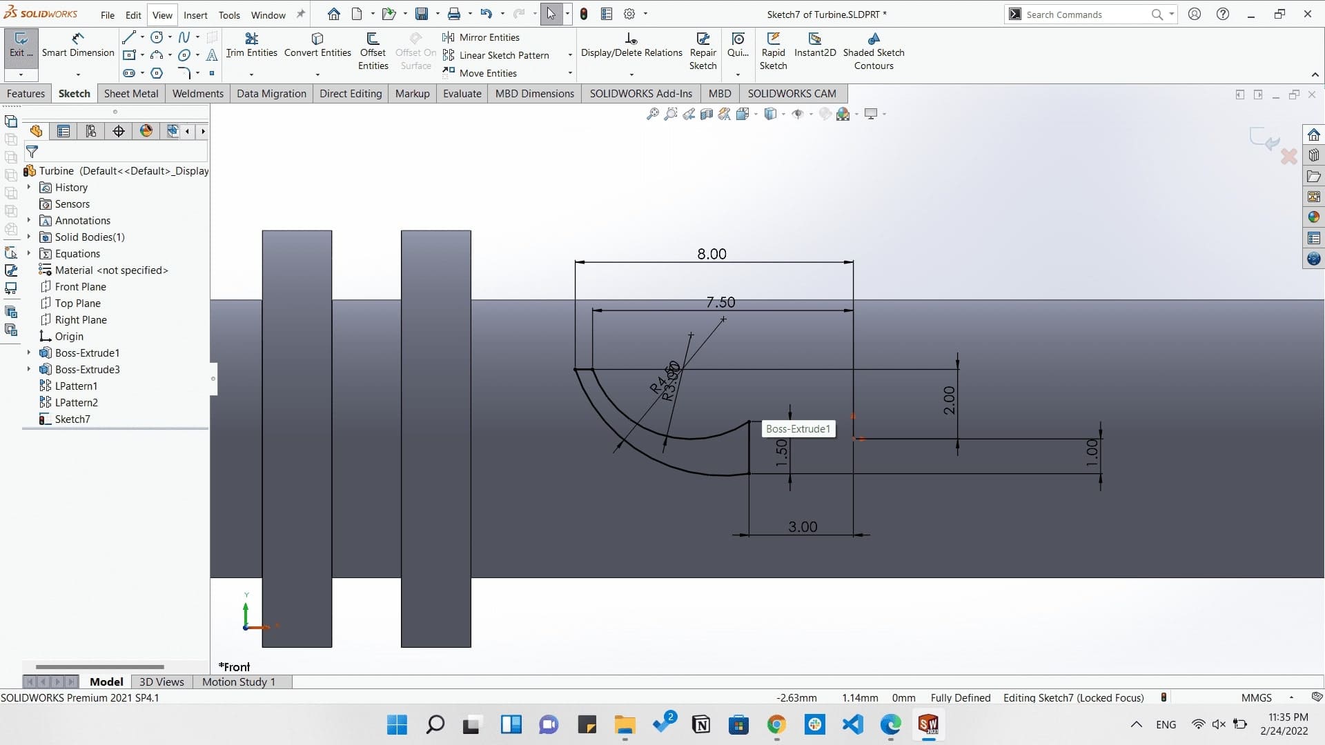
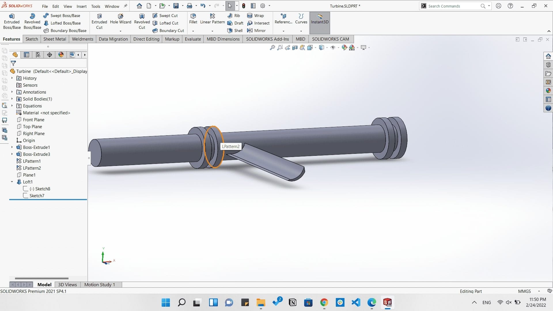
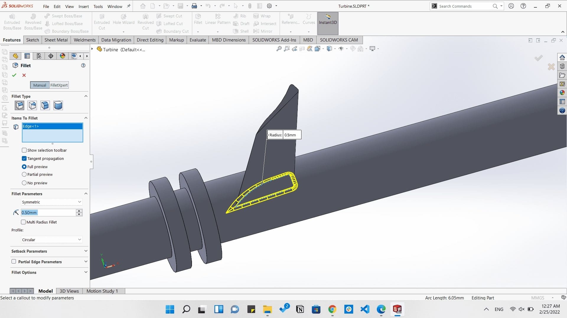
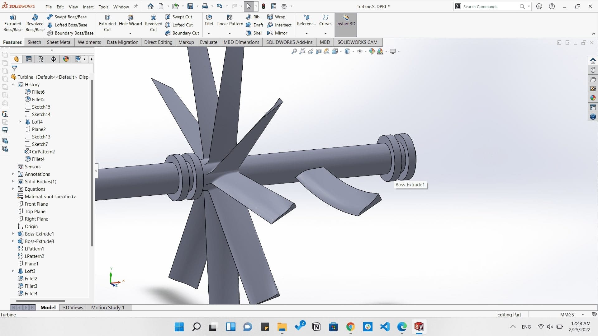
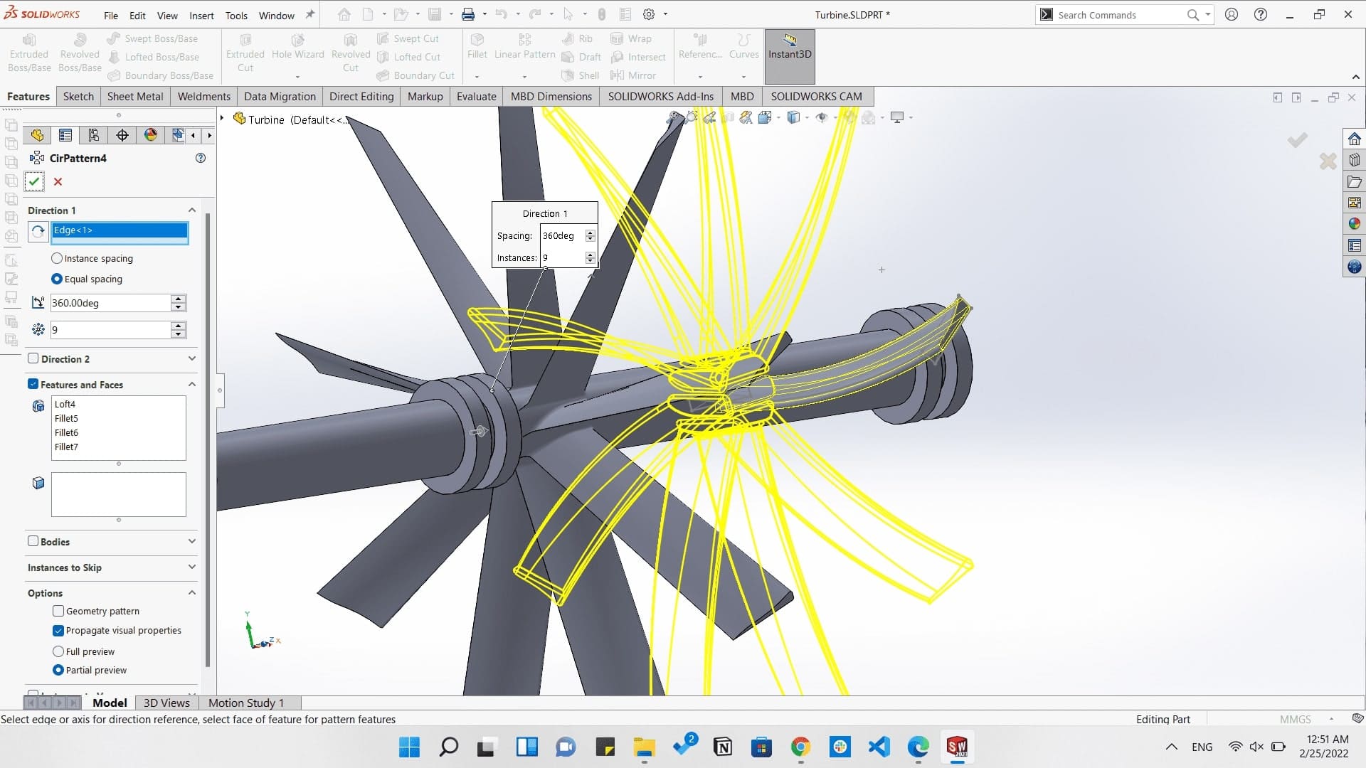
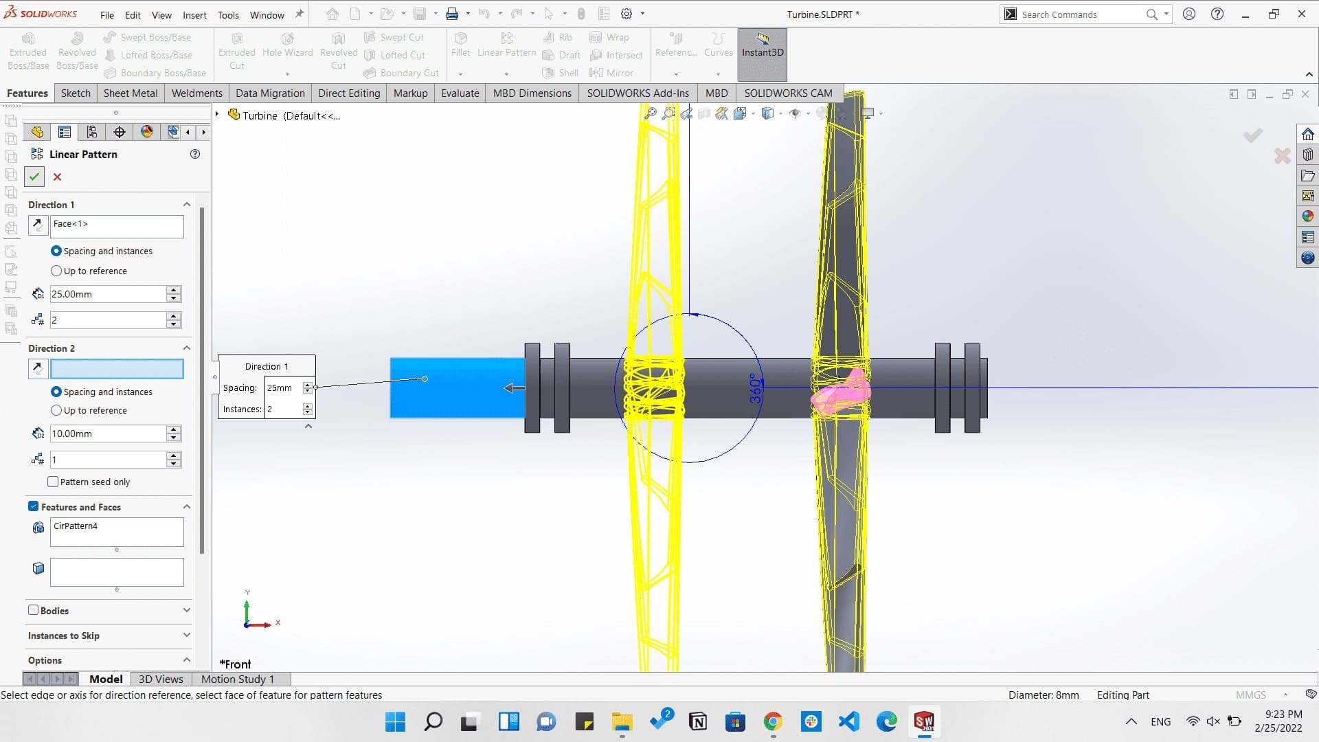
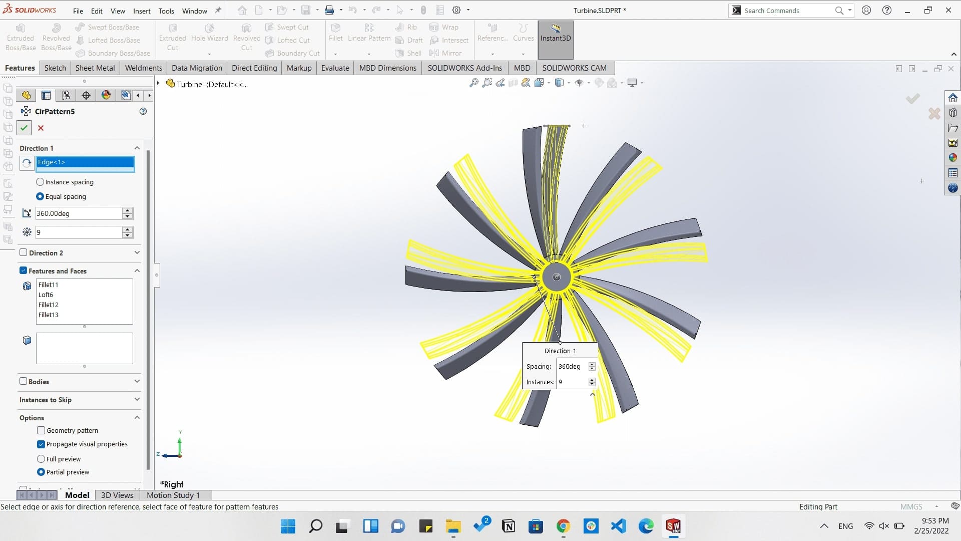
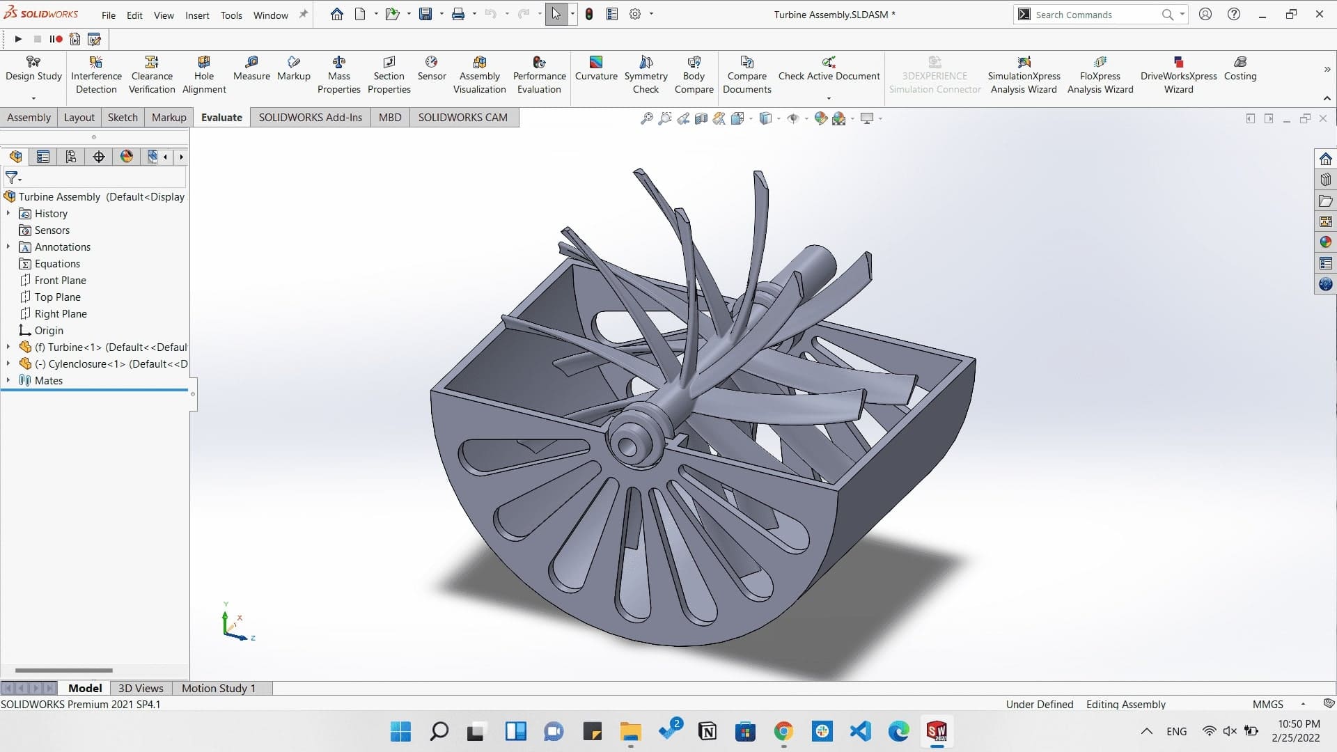
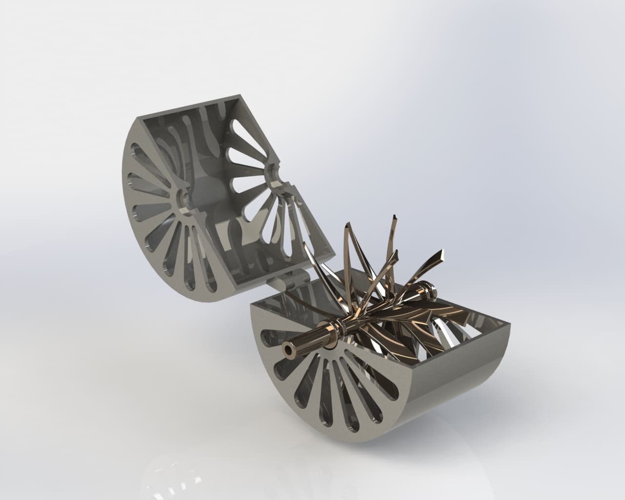
And this is a rendered image made on SolidWorks.
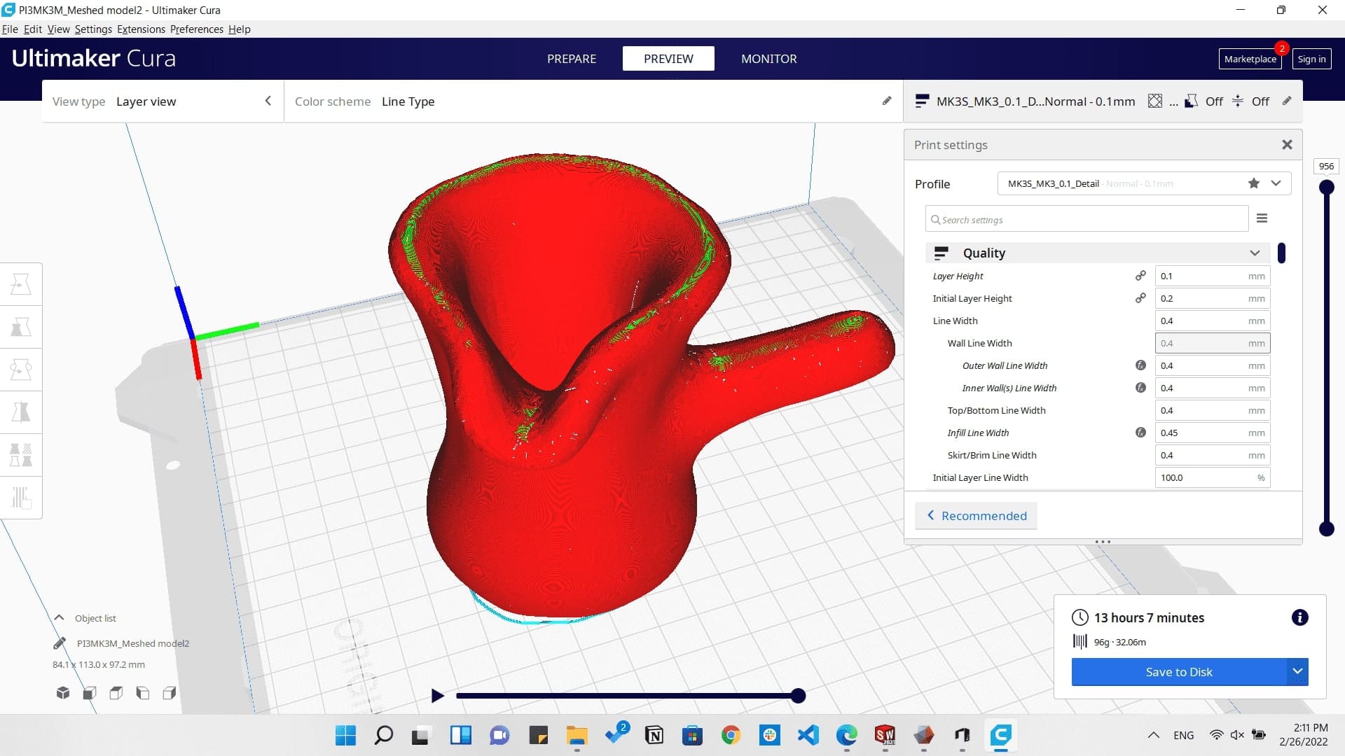
Then for printing the model we need to generate a G-code which the machine understands. So by downloading Cura Slicer and slicing the model by the following settings to get the most perfect output possible.
- Layer height: 0.2mm
- Infill: 20%
- Enabling support
- Speed: 50mm/s
- Material: PLA+
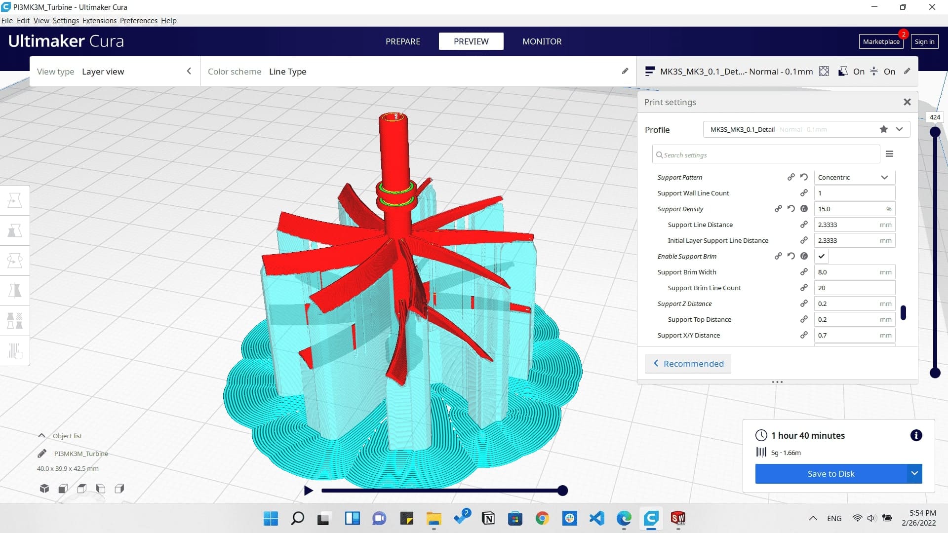
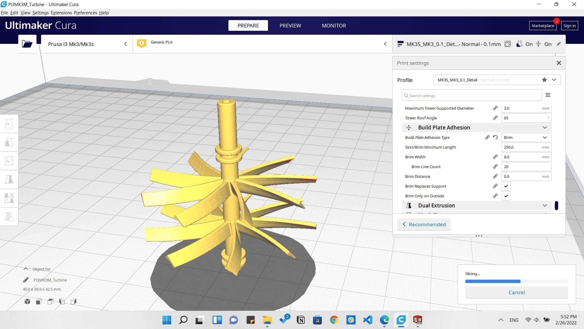
Slicing the turbine
And then I managed on 3D printing them.
3D printing the turbine
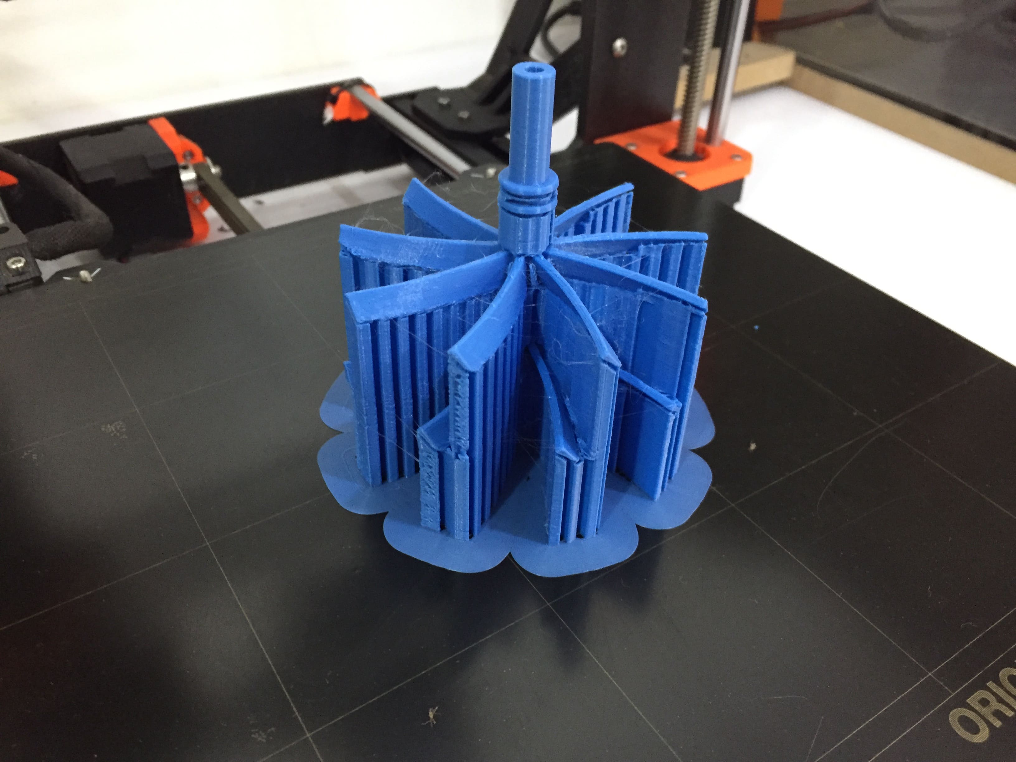
Printing the turbine
After removing the support.
The hinge working perfectly
Turbine assembly
Turbine in action
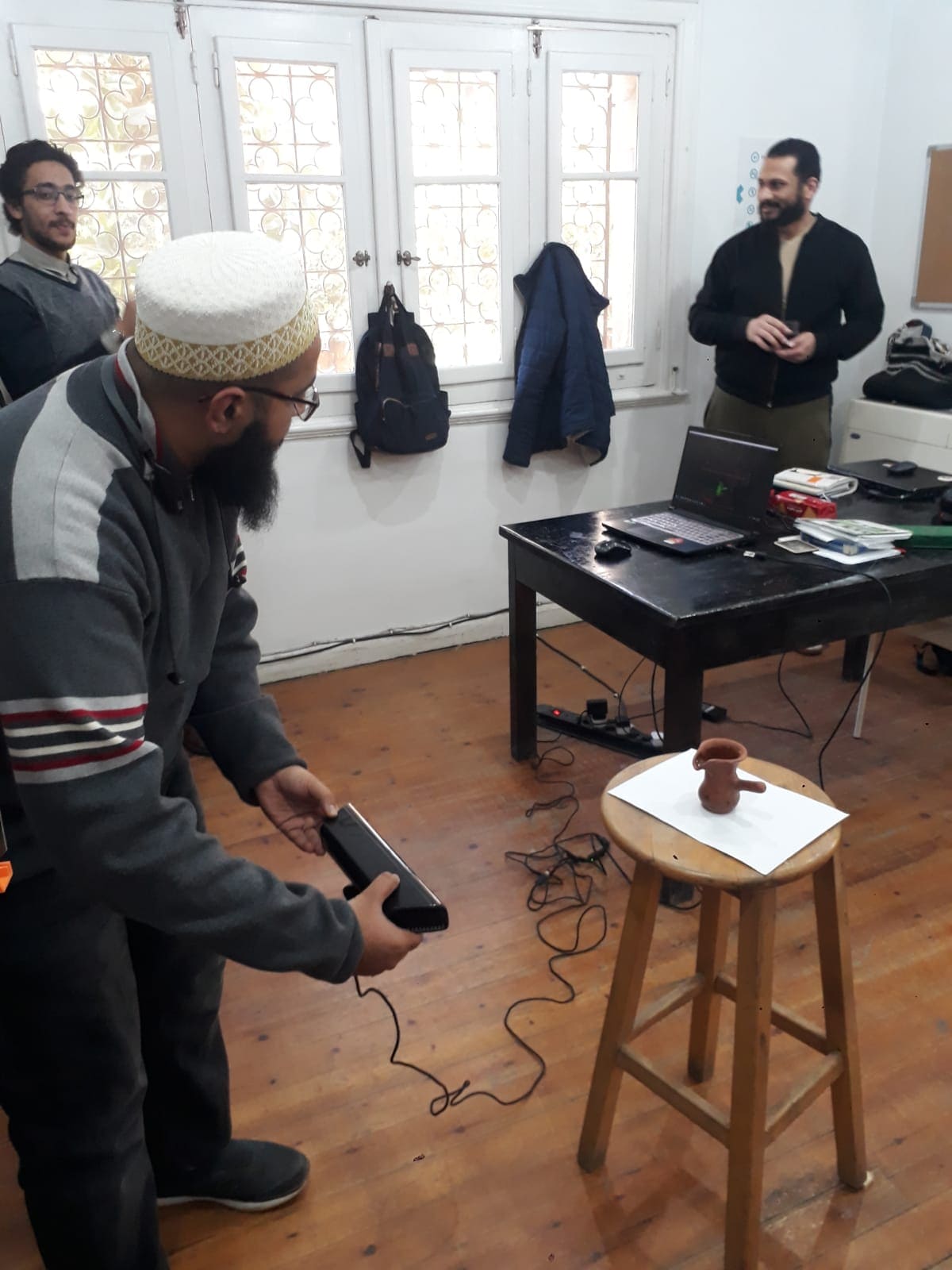
3d Scanning
This assignment was interesting in many ways as it was my first time to 3D scan an object. and I had 2 ways to 3D scan an object.
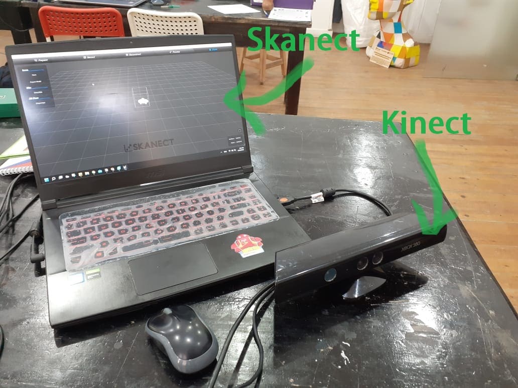
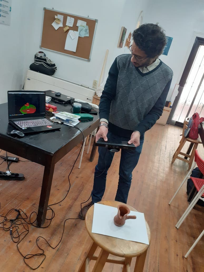
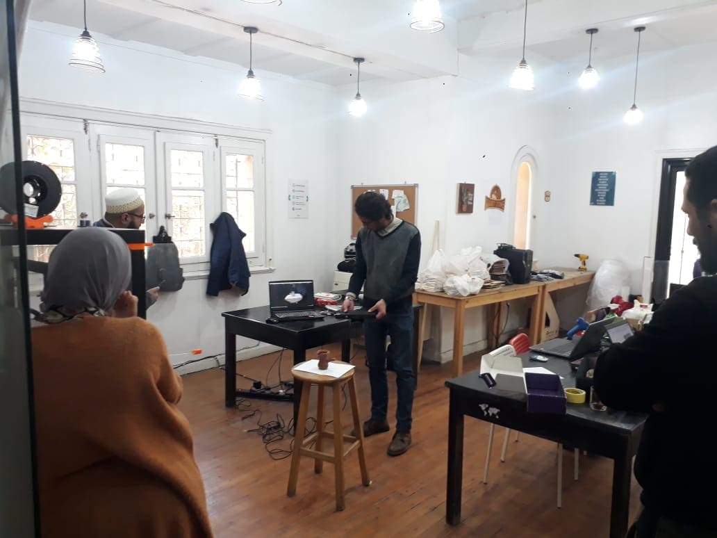
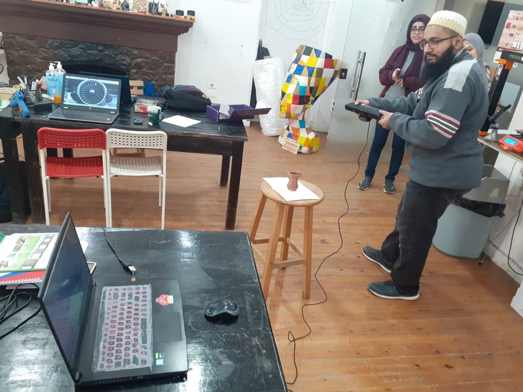
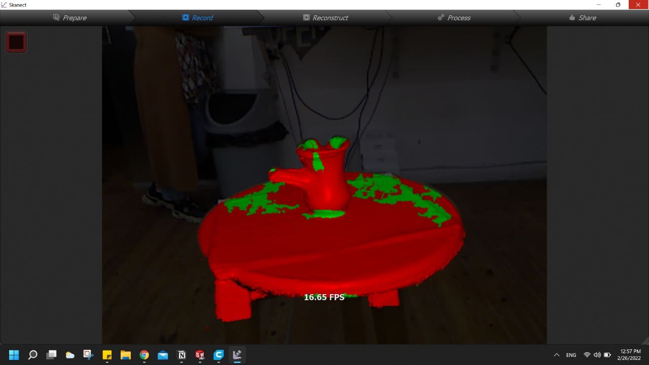
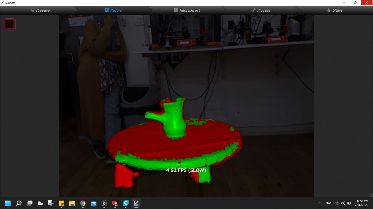
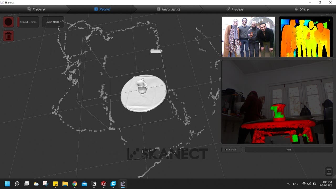
This first was a bit professional as we had Kinect from Microsoft at the lab and by using the Skanect software we managed to 3D scan our object.
And as a group we started to scan the object very slowely and getting every part of it scanned as much as possible.
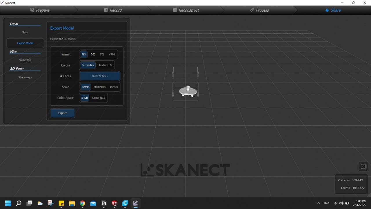
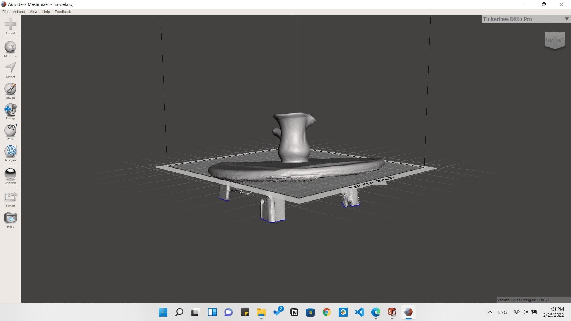
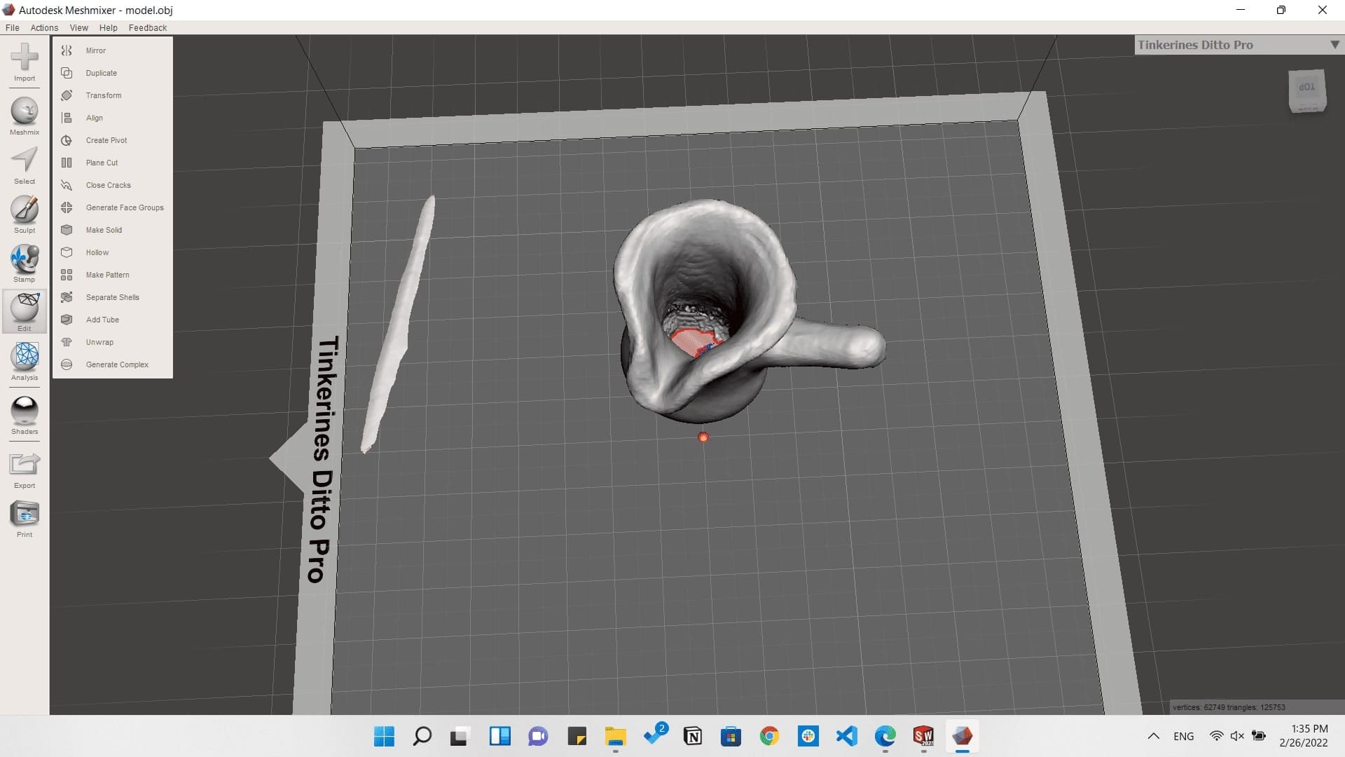
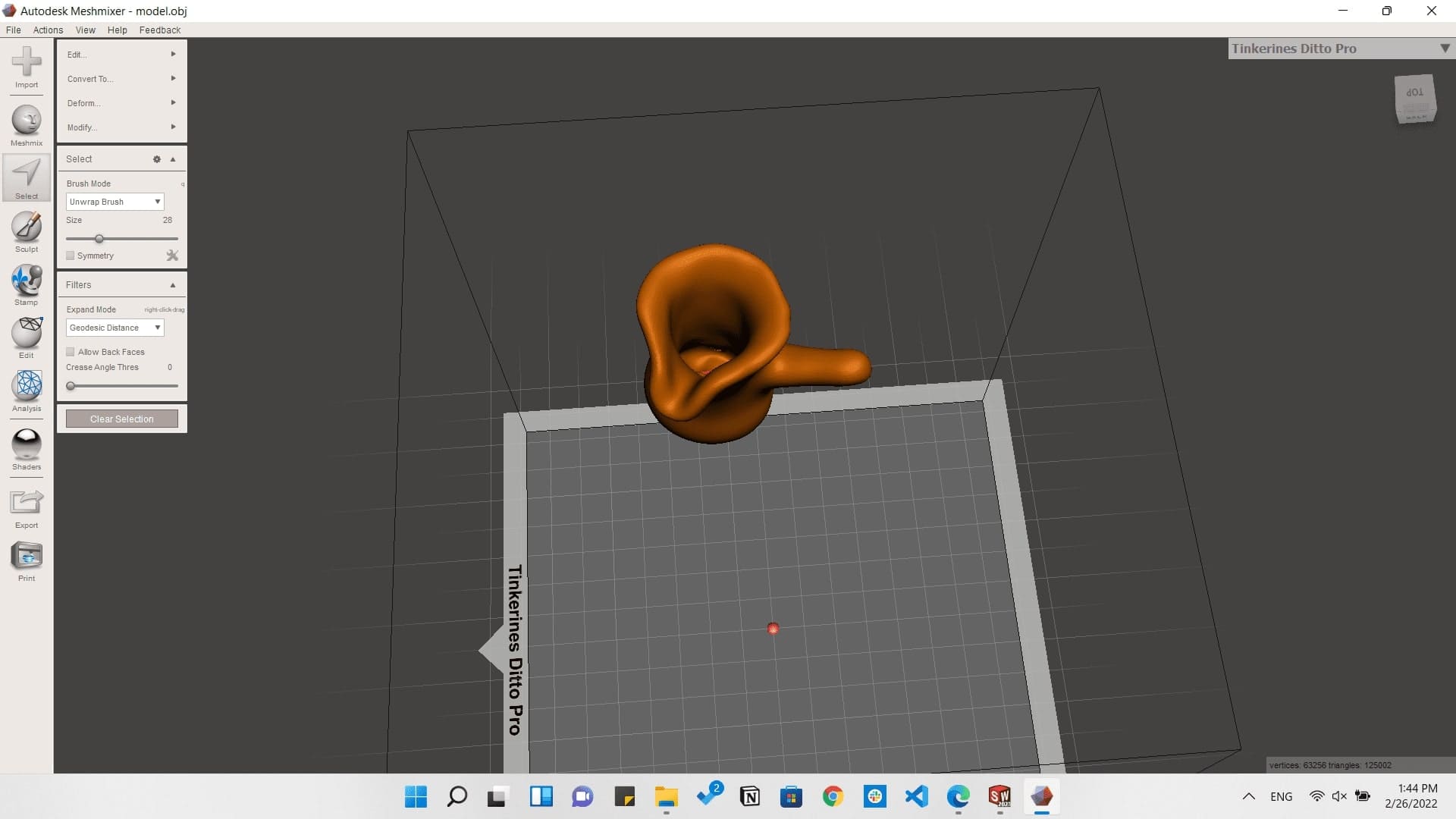
Then we had to do some edits on the stl file generated to get a perfect shape able to be printed.
So I worked on Meshmixer software which is very helpful in editing stl files.
The second option I had in 3D scanning was using QLONE application which is available on smart phones app stores.

And I started scanning a 3D printed model of the Colesseum and it came out as shown below.
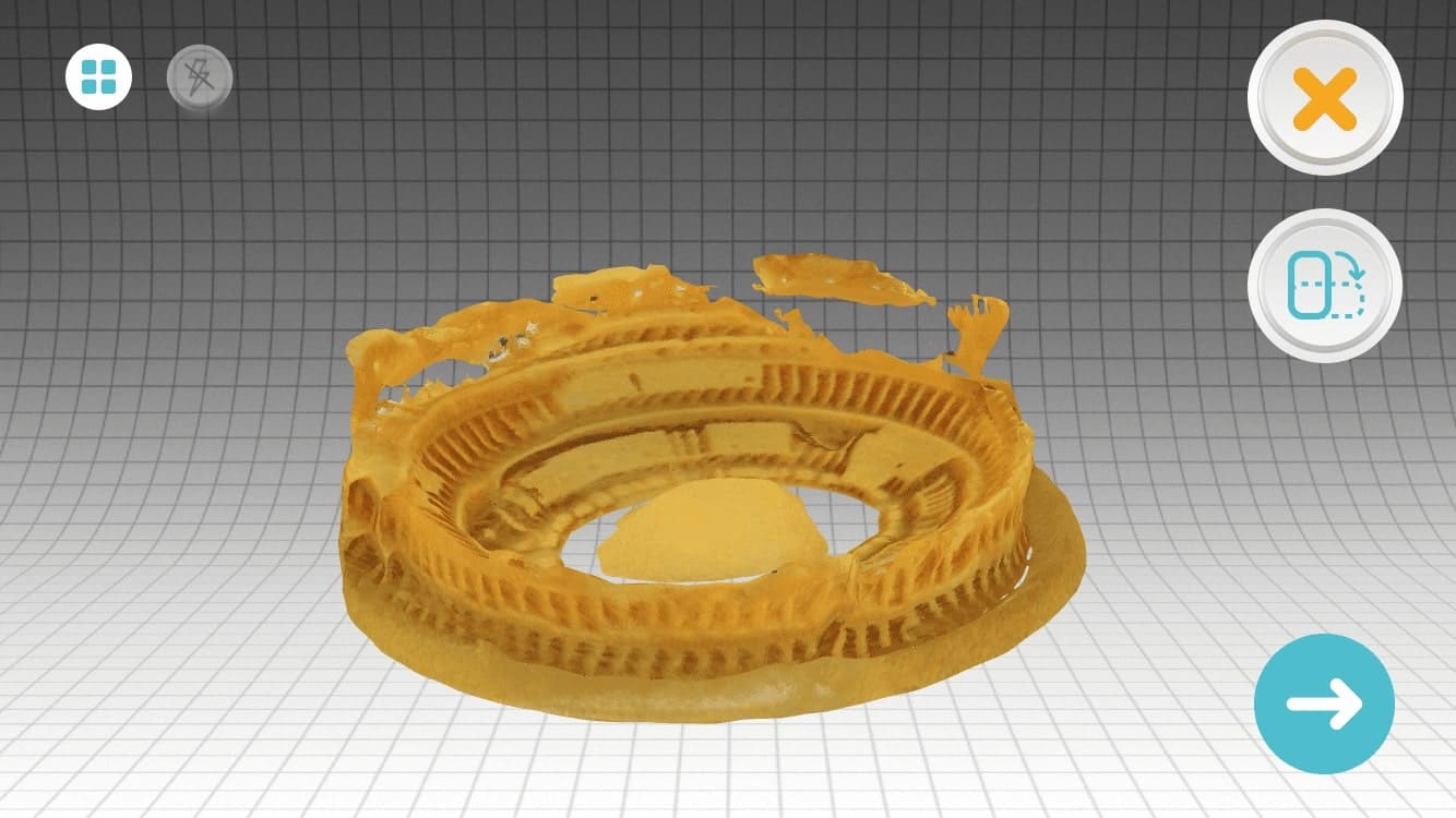
A Gif exported from QLONE
Downloads
What an interesting week!!