
Week 4
Electronics Production
This week we are producing and working on some interesting electronics.
- Group Assignment.
- characterize the design rules for your in-house PCB production process.
- Individual Assignment
- Make an in-circuit programmer by milling and stuffing the PCB, test it, then optionally try other PCB fabrication processes.
Intro
Basics of Microcontroller Unit (MCU)
Developing an MCU consists of 2 steps
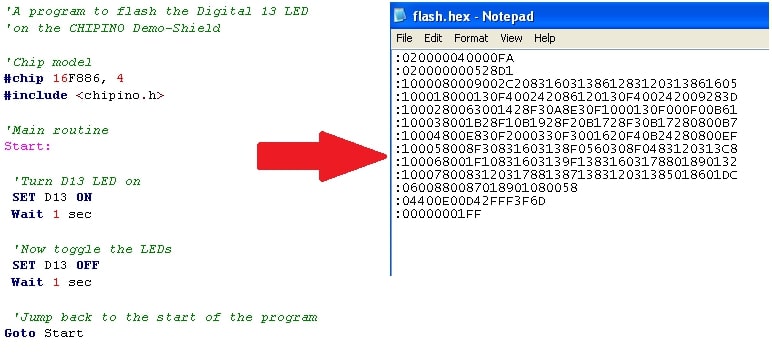
A. Step 1
Writing a desired code in any language you need on your PC and then converting it to a Hex file. As writing a code will be code.c then after converting it to hex file it becomes code.hex
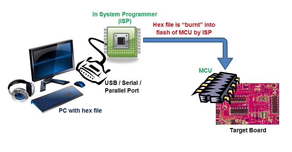
B. Step 2
Then we need to burn the code we have written on the flash memory of the MCU we have and that happens by programming the hex file we made from the PC and it reads first the amount of memory available and makes an erase cycle then it burns the new code on the memory, and we will be going exactly how to do this in this week.
Resources: maxEmbedded, Electronic Products
Group Assignment
In this assignment we need to characterize the design rules for our PCB production process: document feeds, speeds, plunge rate, depth of cut (traces and outline) and tooling.Here at Fab Lab Egypt we have 2 milling machines: A Rolland MDX-20 milling machine and a CNC china milling machine So we decided to characterize both machines, starting with the modella MDX-20.
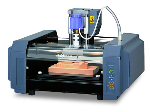
Rolland MDX-20 Milling machine
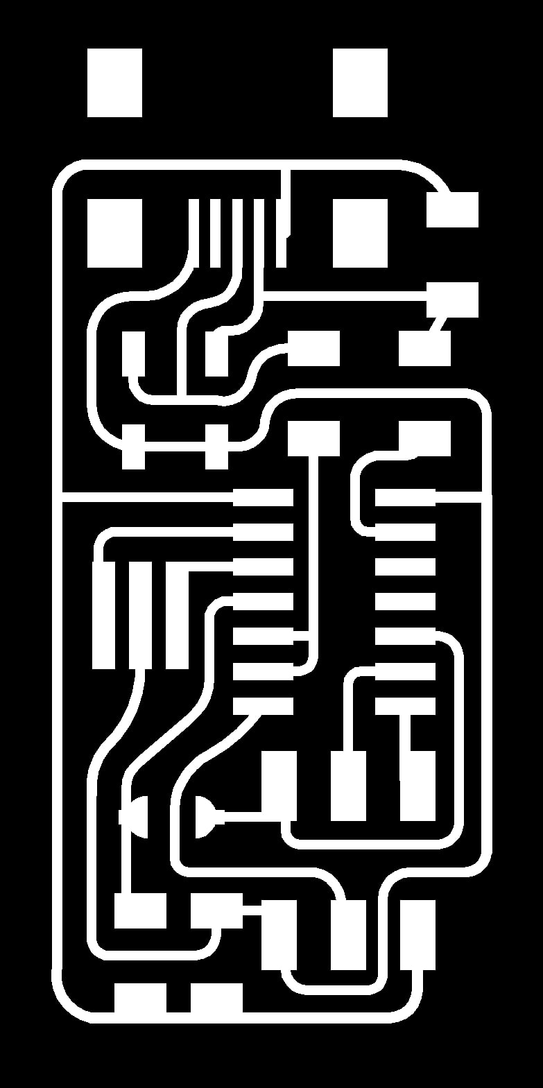
First, we need to download the png files for the traces and outline as shown below.
Traces

Outline
Then we will be working on Mods to operate the Modella machine.
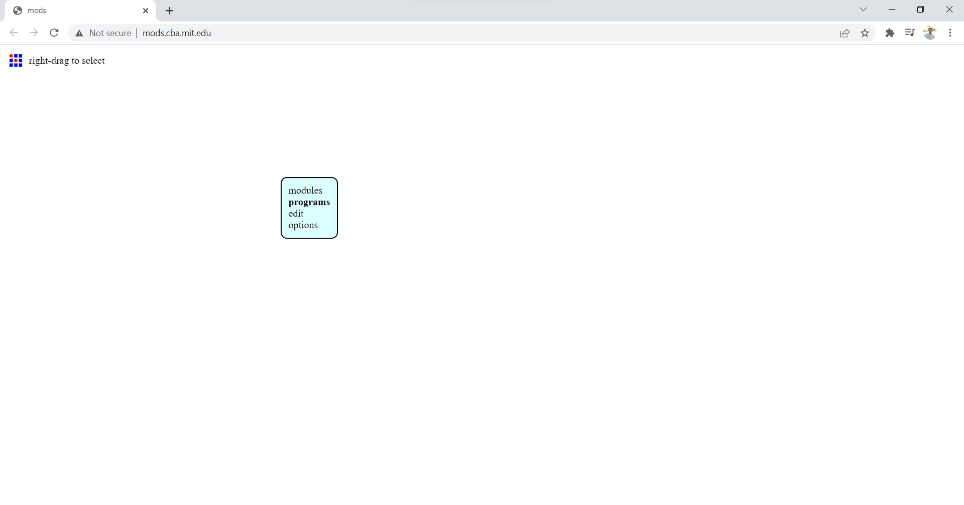
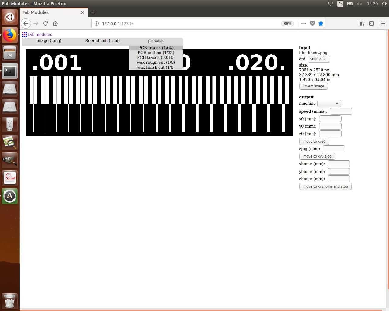
Entering the modules and programs on mods, you only to right click anywhere. So we will start by the traces file, so follow the steps.
1. Right click and choose Programs.
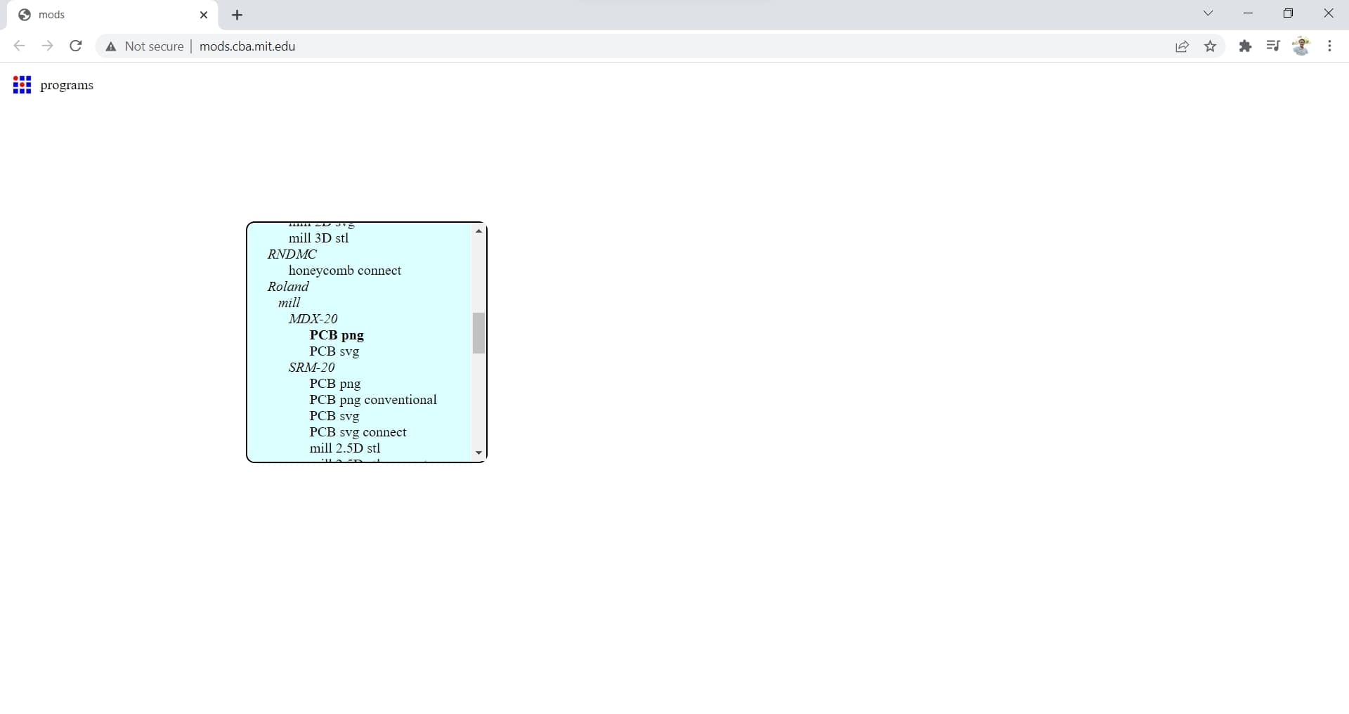
2. Choose Open server module.

3. Scroll down till you find Machines>Rolland>MDX-20>PCB png.
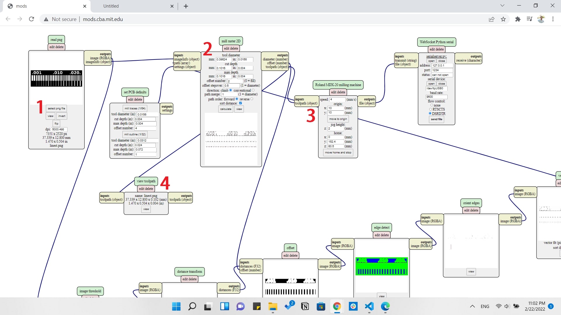
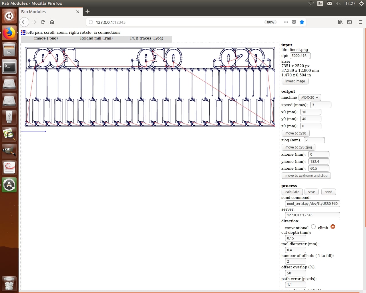
4. Edit all parameters for milling by setting:
- Selecting the png of the traces
- Setting the Tool diameter to 0.4mm, Cut depth to 0.1mm and Offset to 2
- Setting the Origin point for the PCB manually according to where the board is fixed on the bed
- This is just a view of the tool path that will open on a new page automatically
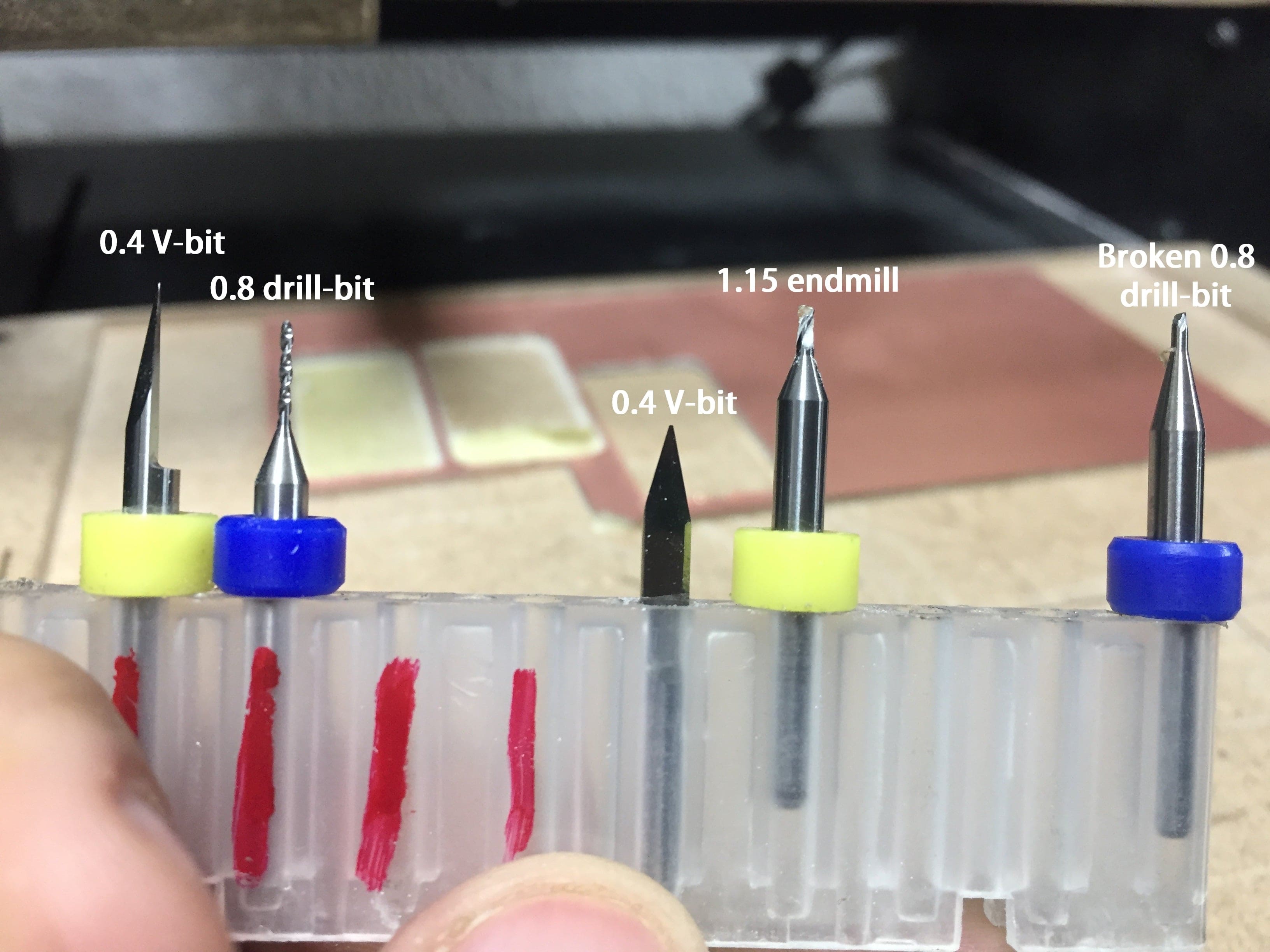
And here we can see the difference between the bits we are going to use.
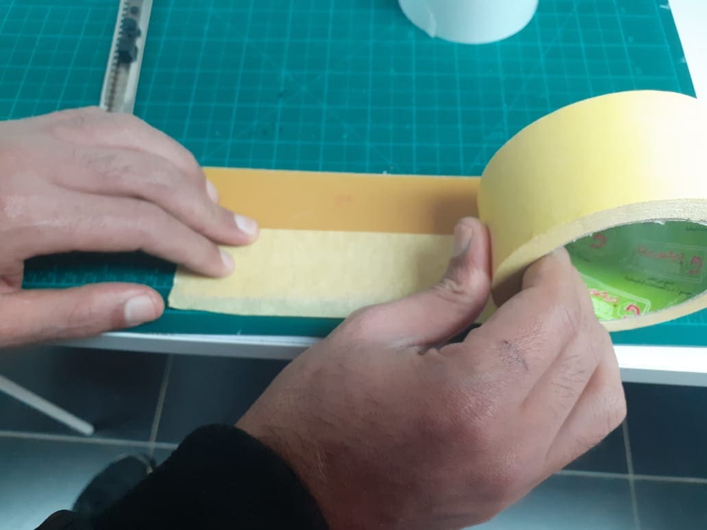
Then we will apply double sticky face tape on our sheet to stick it on the machine's bed.
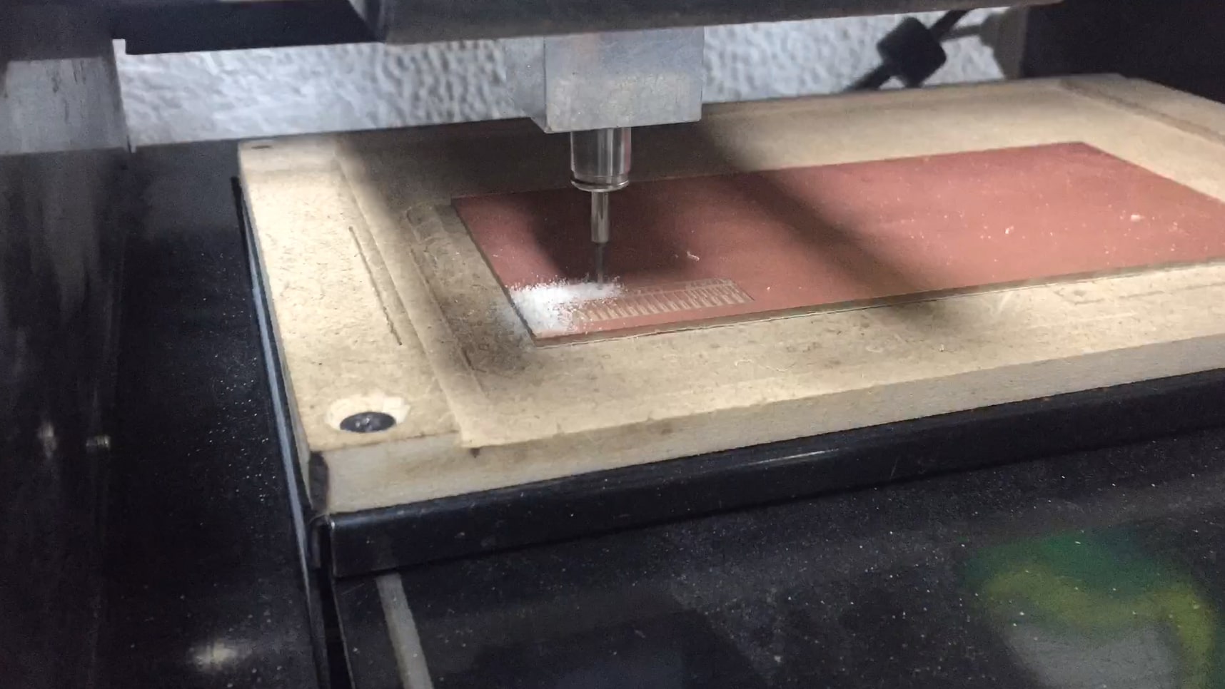
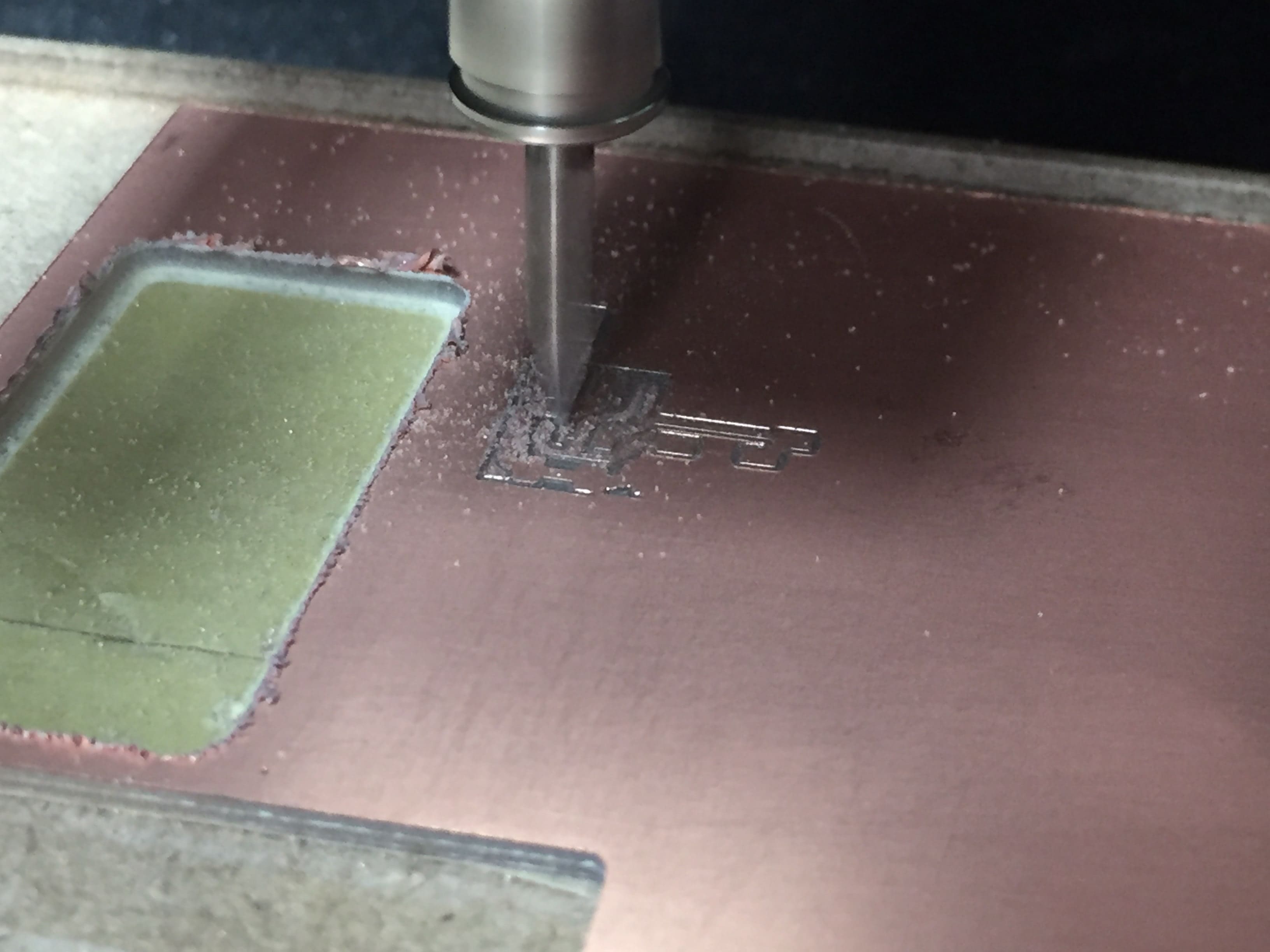
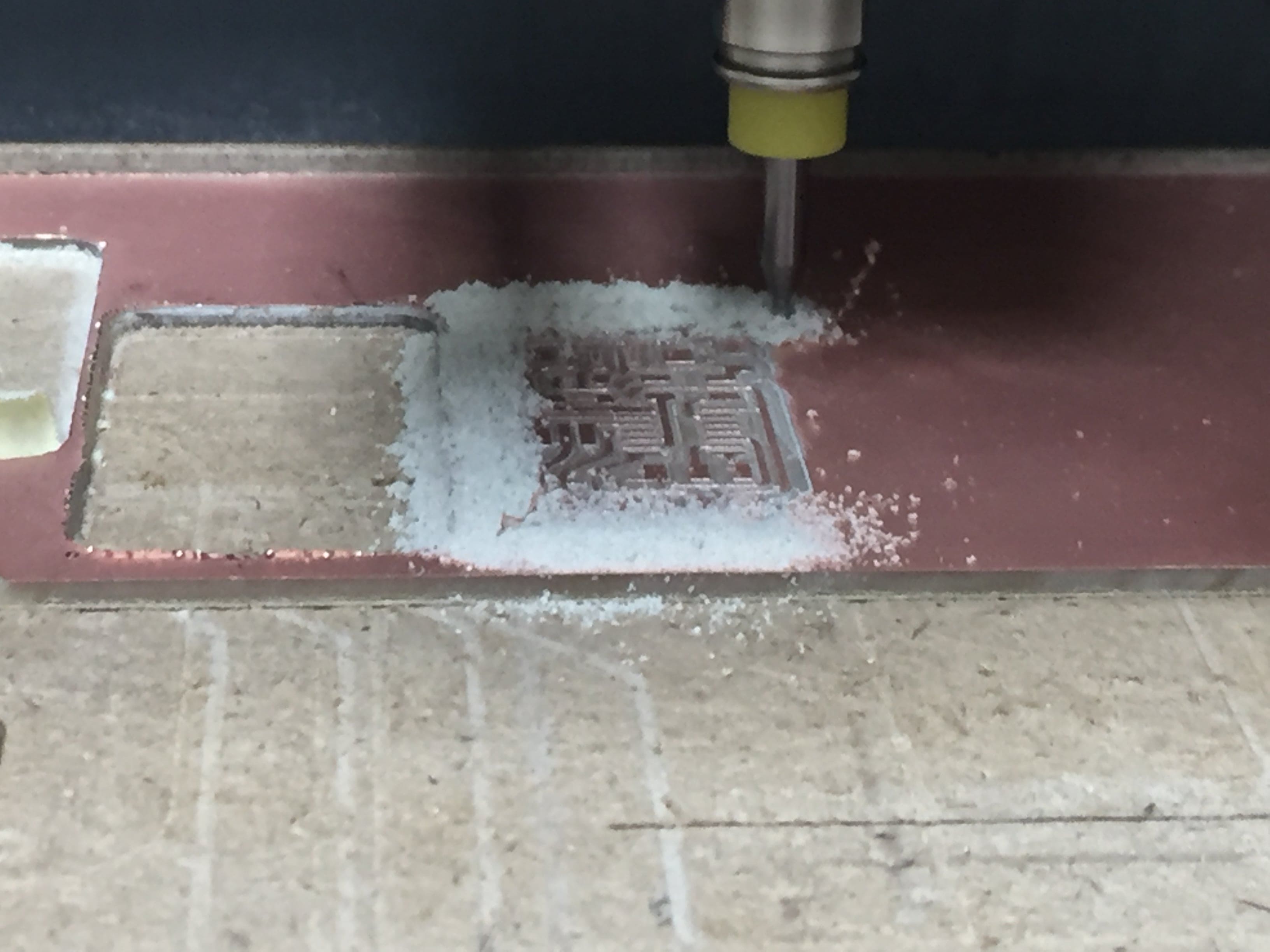
Then we will start milling the traces and cutting the outline.
And get this fantastic output.
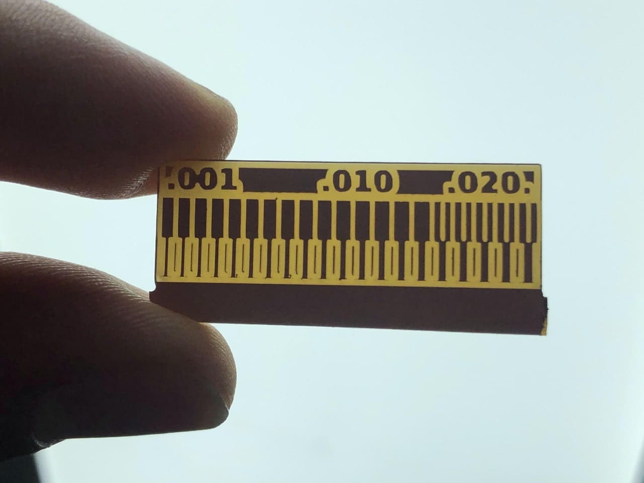
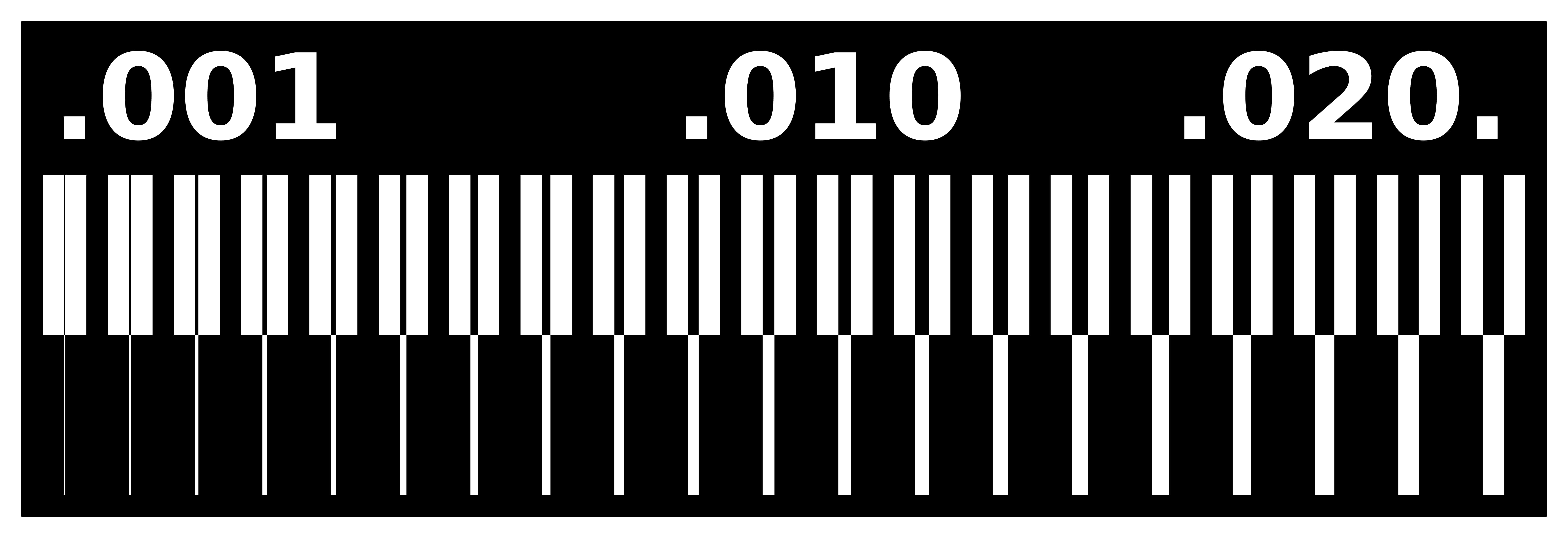
Conclusions
A. The minimum trace width the machine can mill is 0.001mm.
B. The minimum distance between traces is 0.42mm.
Individual Assignment
Here we are going to fabricate and program our board that can program any other board later.
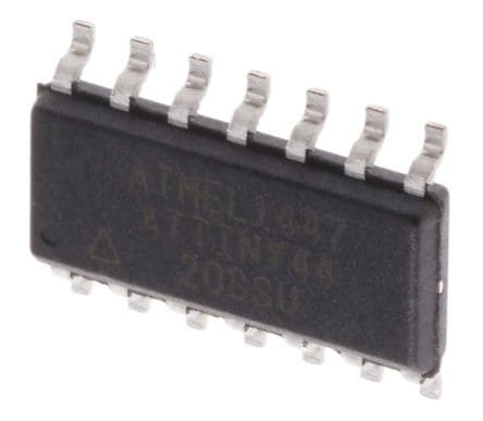
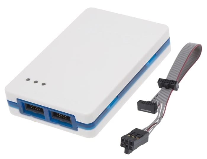
So we will start by choosing our In-System Development and I chose ISP (Original AVR) and Attiny44 as a Microcontroller with ATAMEL-ICE as a programmer.
Fabricating the (FabISP)
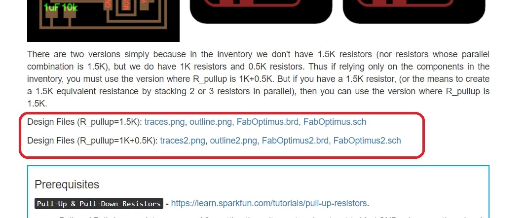
There were several FabISP boards but I managed to choose Ali Shtarbanov's board.
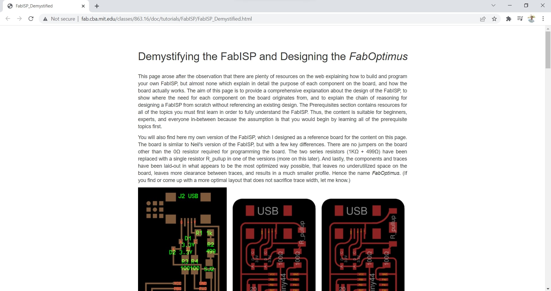
And you can find the design files for the board attached below the pictures.
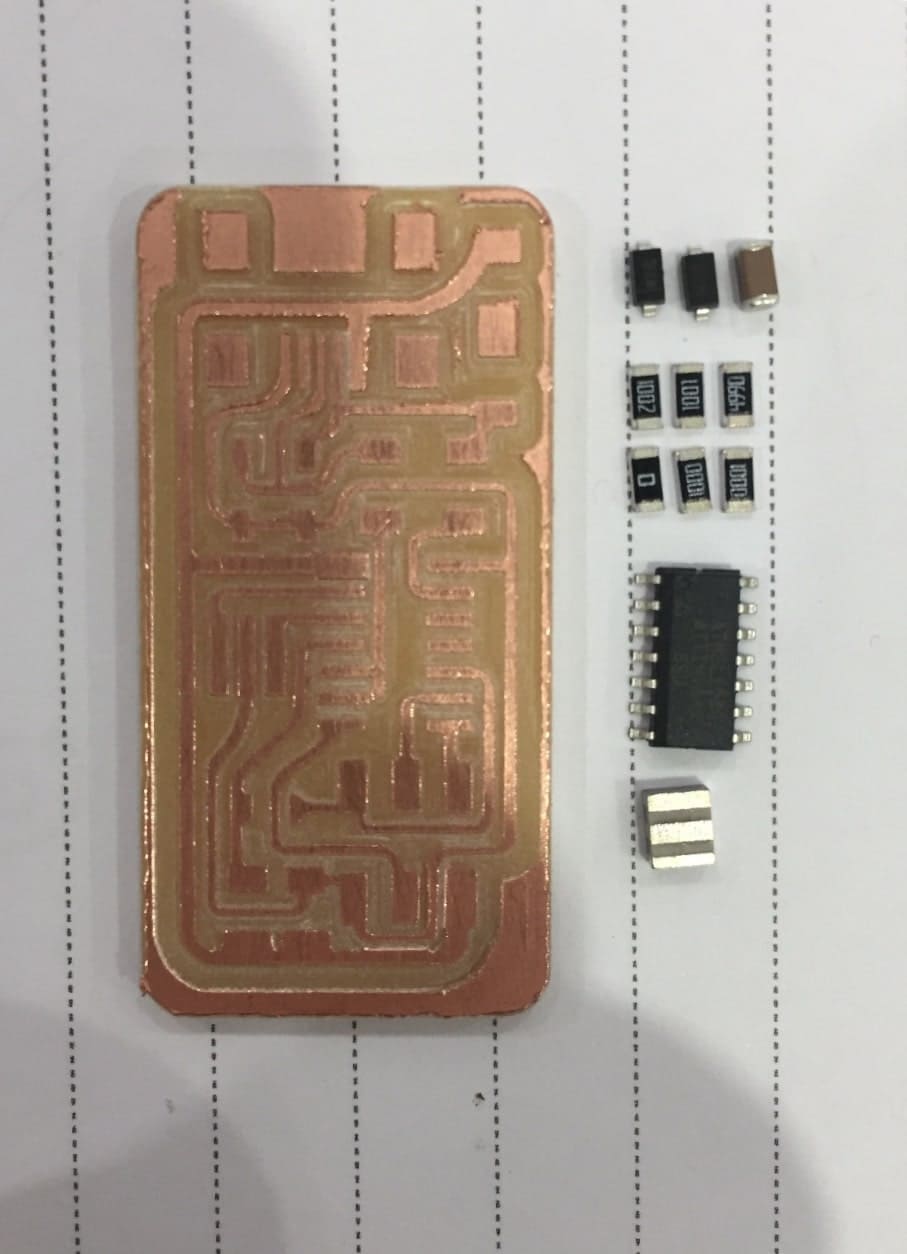
Then we will have the png files ready for fabricating as we did earlier.

I also wanted to work on Fab modules after trying mods, so as we had it installed locally at our Lab, I started milling it.
And the same process we made earlier we are going to make here again from applying the double-face tape, setting X and Y coordinates, milling and cutting the outline. So enjoy the photos.
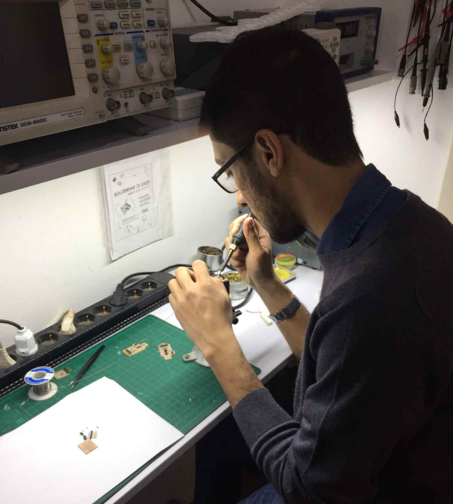
Soldering the FabISP
First we have to get our SMD> components ready, and you can find them in the following table:
| Name | Datasheet | Quantity |
|---|---|---|
| ATTINY44A-SSU-ND | Attiny44 | 1 |
| USB - mini B | UX60A-MB-5ST | 1 |
| Headers & Wire Housings 6P | 95278-801A06LF | 1 |
| SMD 10 kOhms 250 mW Resistor | RC1206FR-0710KL | 1 |
| SMD 1 kOhms 250 mW Resistor | RC1206FR-071KL | 1 |
| SMD 100 Ohms 250 mW Resistor | RC1206FR-07100RL | 2 |
| SMD 499 Ohms 250 mW Resistor | RC1206FR-07499RL | 1 |
| SMD 0 Ohms 250 mW Resistor | RC1206JR-070RL | 1 |
| CERAMIC RES 20.0000MHZ 15PF SMD | ECS-CR2-20.00-B-TR | 1 |
| Capacitor CER 1UF 50V X7R 1206 | - | 1 |
| DIODE ZENER 3.3V 500MW SOD123 | BZT52C3V3-7-F | 29.99 |
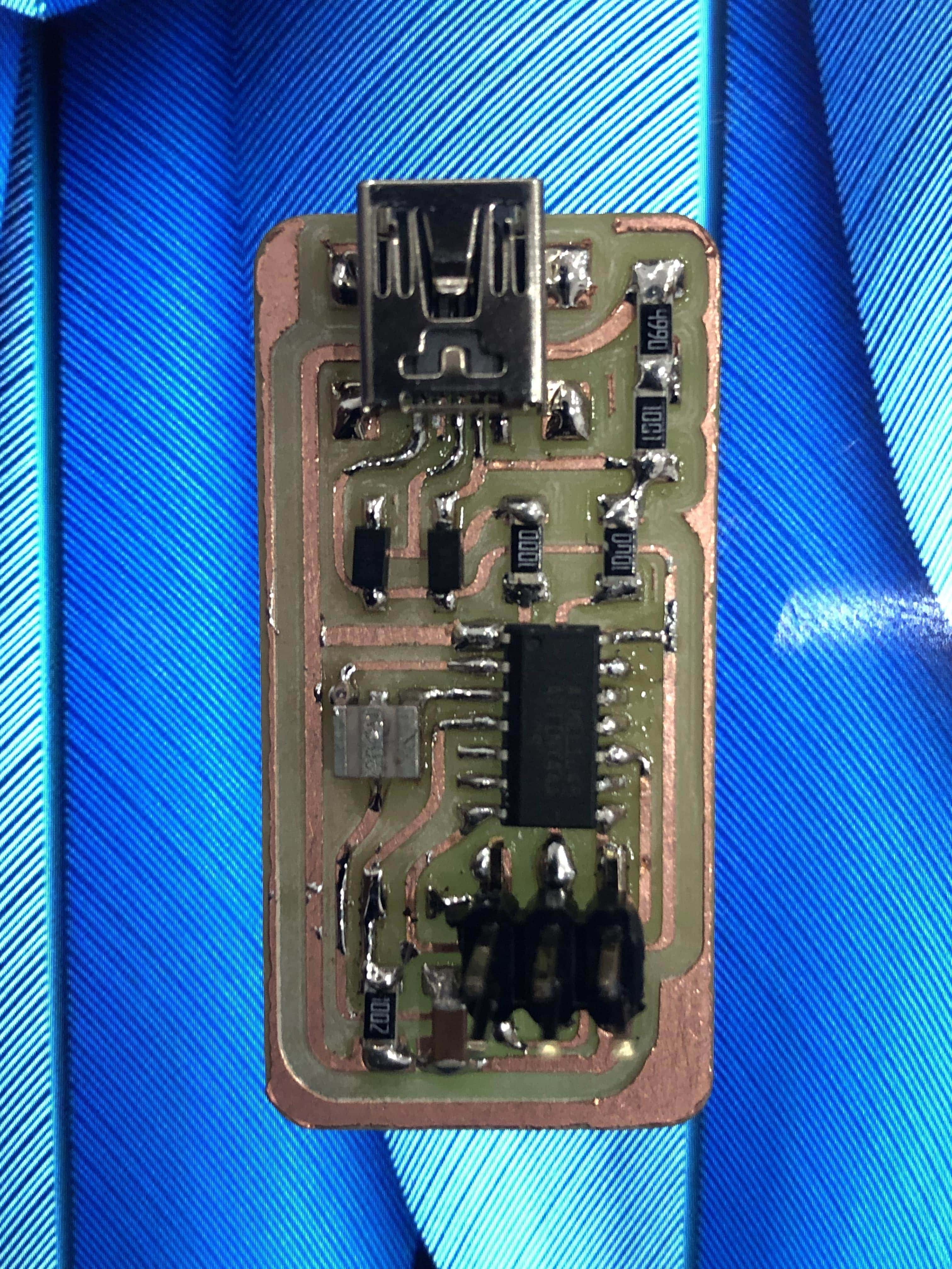
Then I soldered the components according to the schematic.
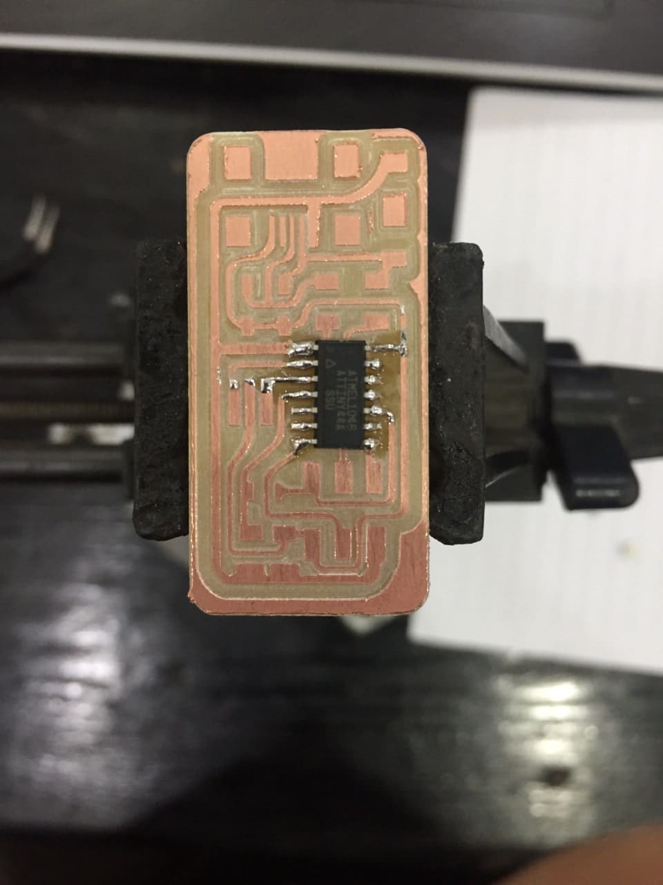
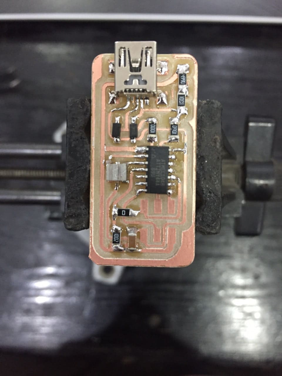
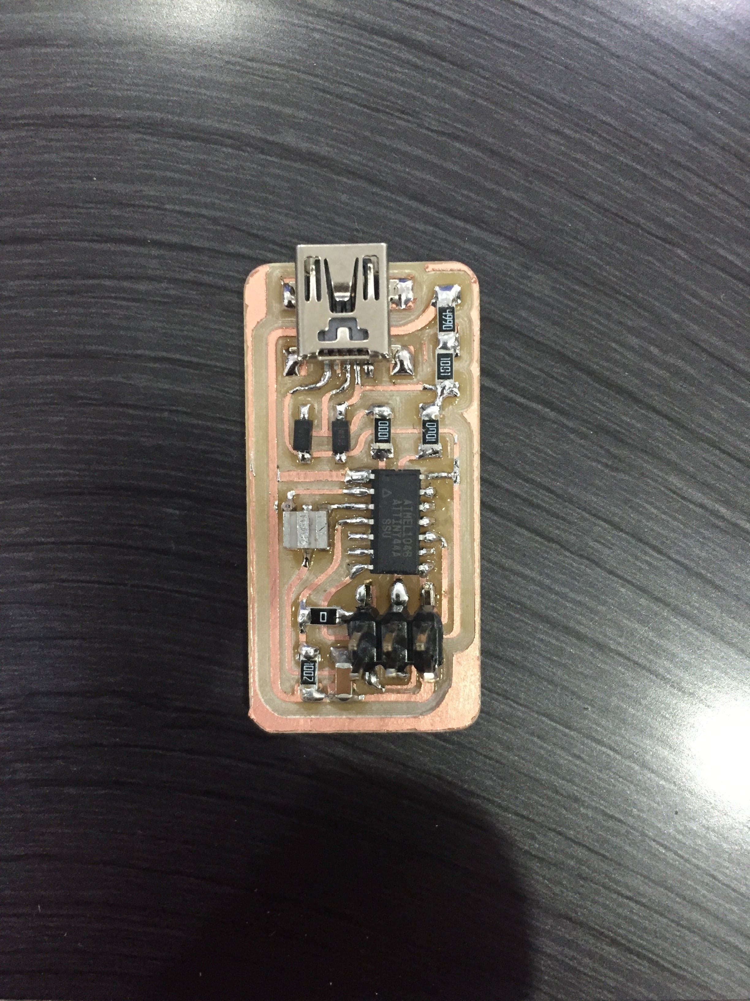
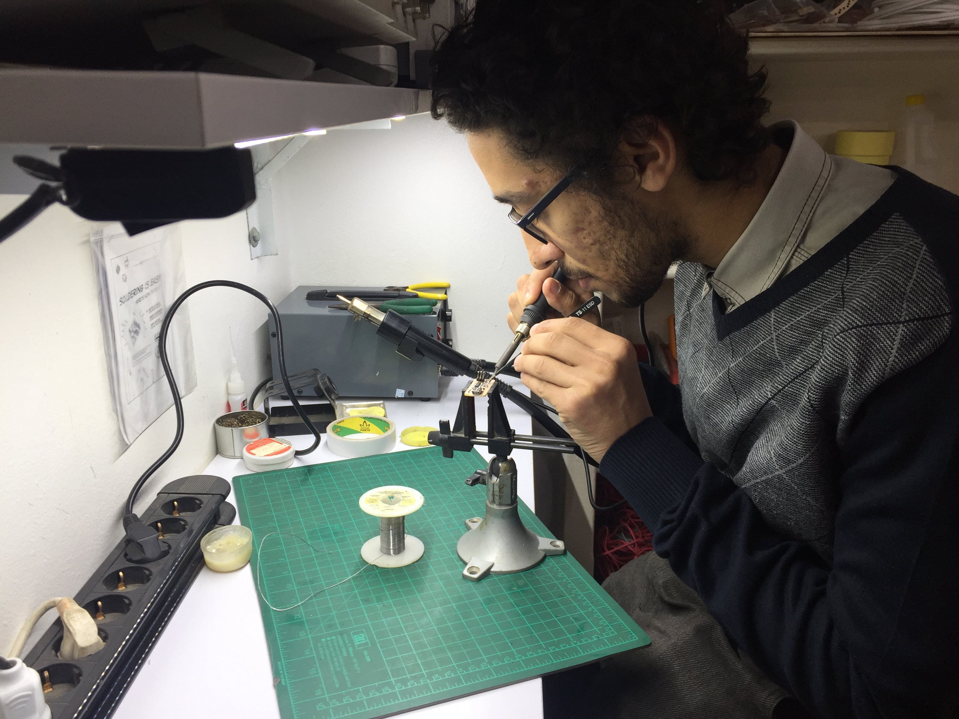
And a hero shot:)
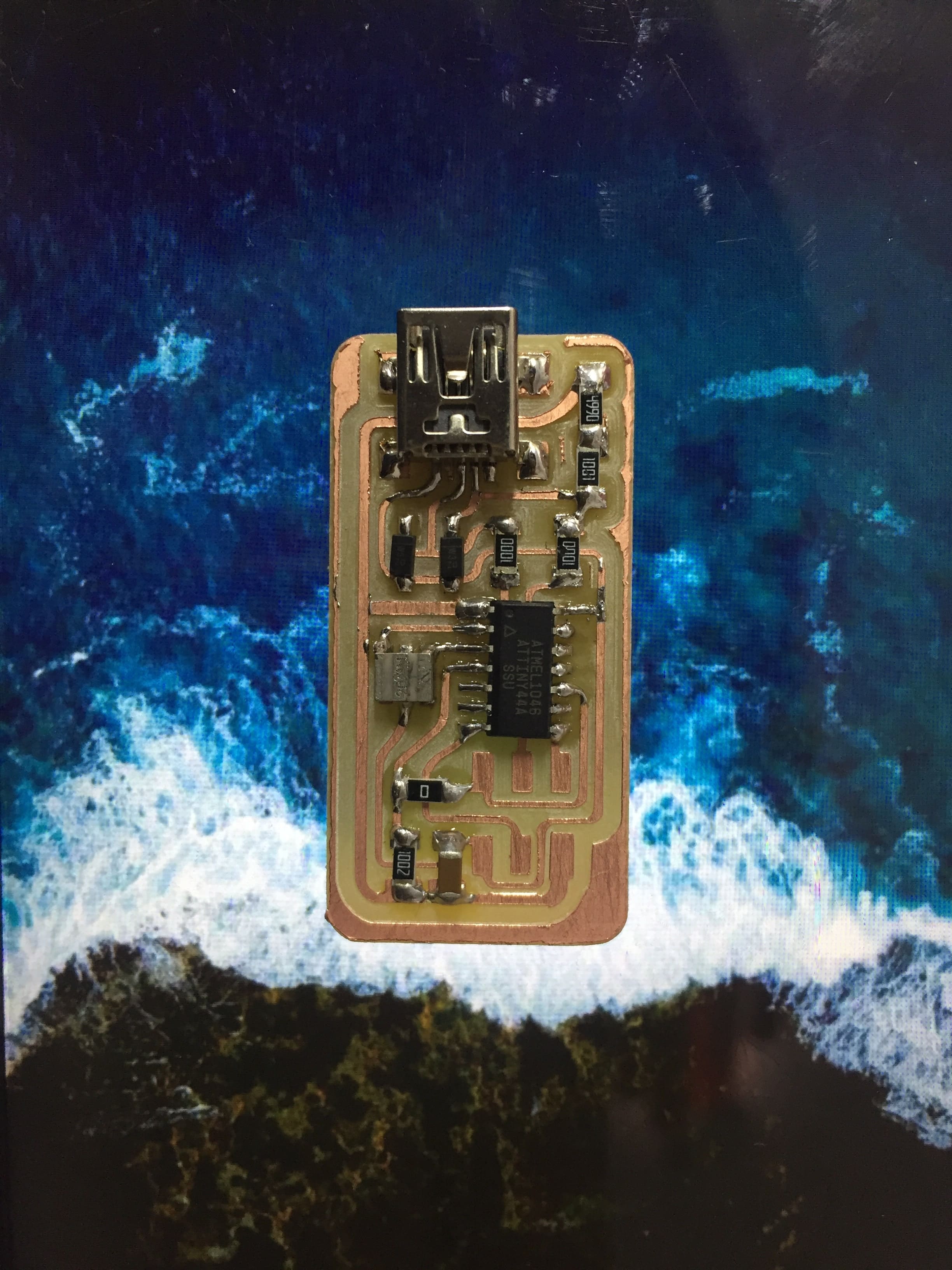
Ta Da!!
Programming the (FabISP)
After that I followed the Using the GNU AVR toolchain tutorial which was really helpful and contained most of the software I needed to download.
Here we will be installing a complete GCC-based toolchain on a modern Windows system, which is windows 11. We need first to install Git Bash since bash is a better terminal program and has a lot more functionality than terminal.
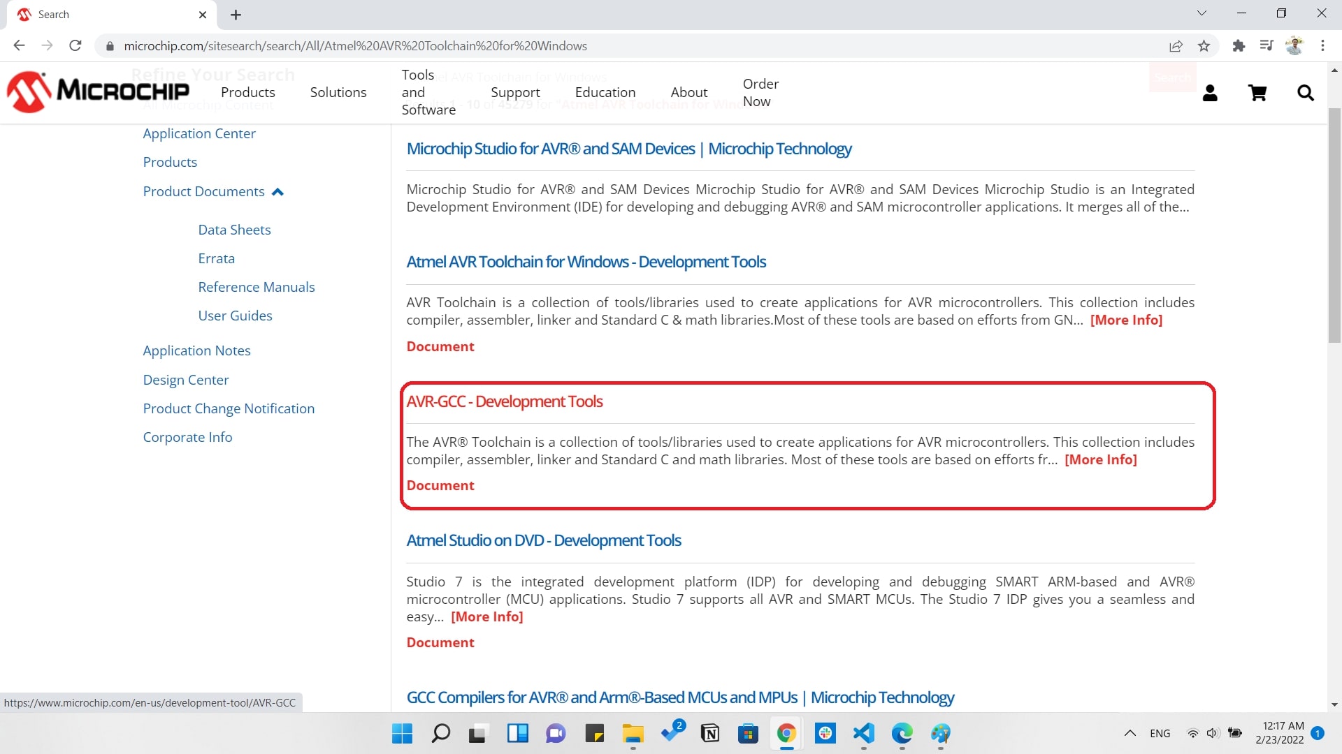
Then a very important step which is downloading and installing Atmel AVR toolchain for Windows
After that we need to download AVR dude and the latest the version you download the better as I managed to download version 6.4. and it's very important to make sure that you archive the avrdude inside C:\ Program Files
After that we shall work on updating our path that tells the system where to locate all the tools we've installed and type their names on the command line. We will go to Control Panel and search for Advance System Settings in the search bar.
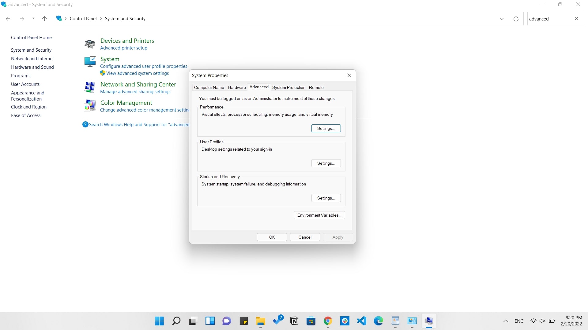
Then we will go under the Advanced tab and click on Environment Variables
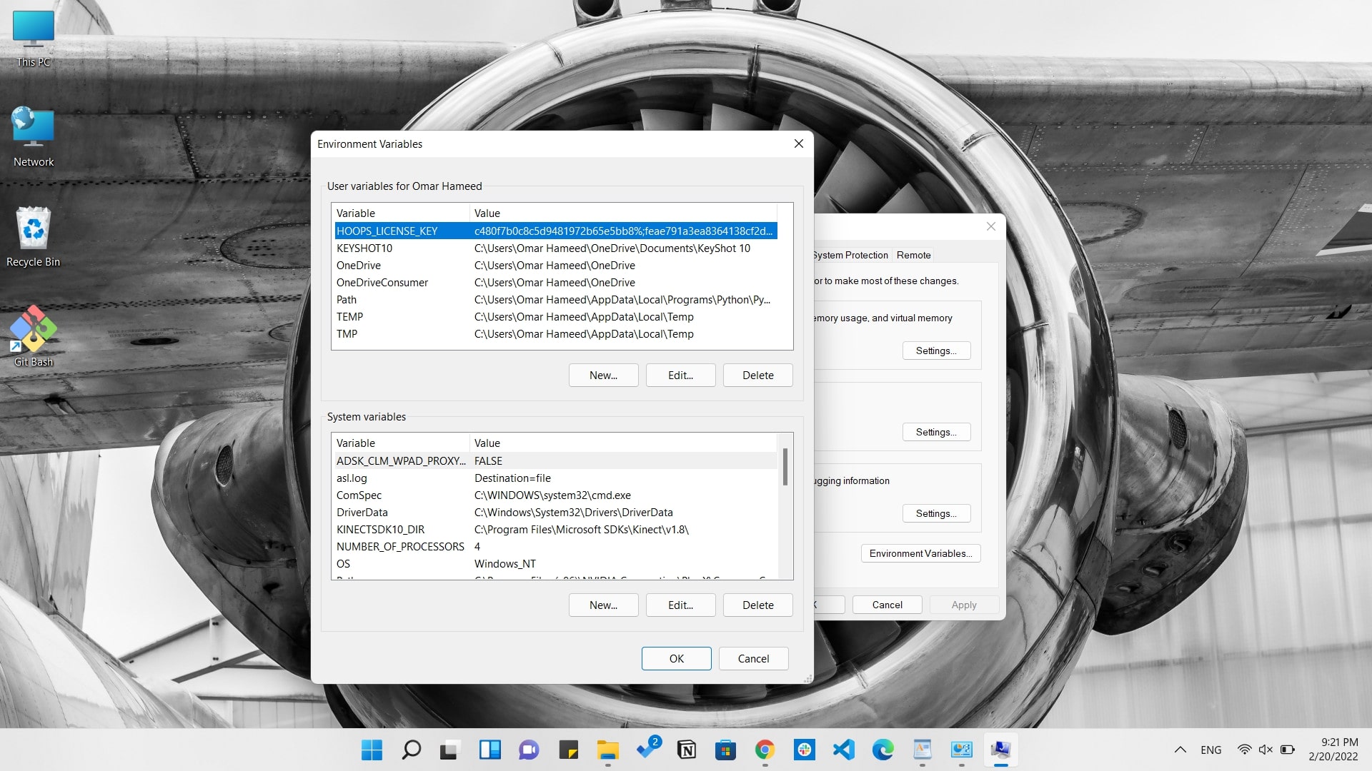
Under User variables, select Path and click the Edit button. If you don't already have a variable called "Path", click the New button to create it, enter "Path" without the name, and fill out the value as described below.
The three values to add are:
- C:\Program Files\avr8-gnu-toolchain\bin
- C:\Program Files (x86)\GnuWin32\bin
- C:\Program Files\avrdude
The last software we need to install is the Zadig that we will need when installing the drivers to our microcontroller.
We will open Microchip Studio, then go to Device Programming after connecting the Atmel-ICE to the computer with the FabISP board we made.
Choose Atmel-ICE in the tool, ChooseAttiny44A in the device, and ISP in the Interface.
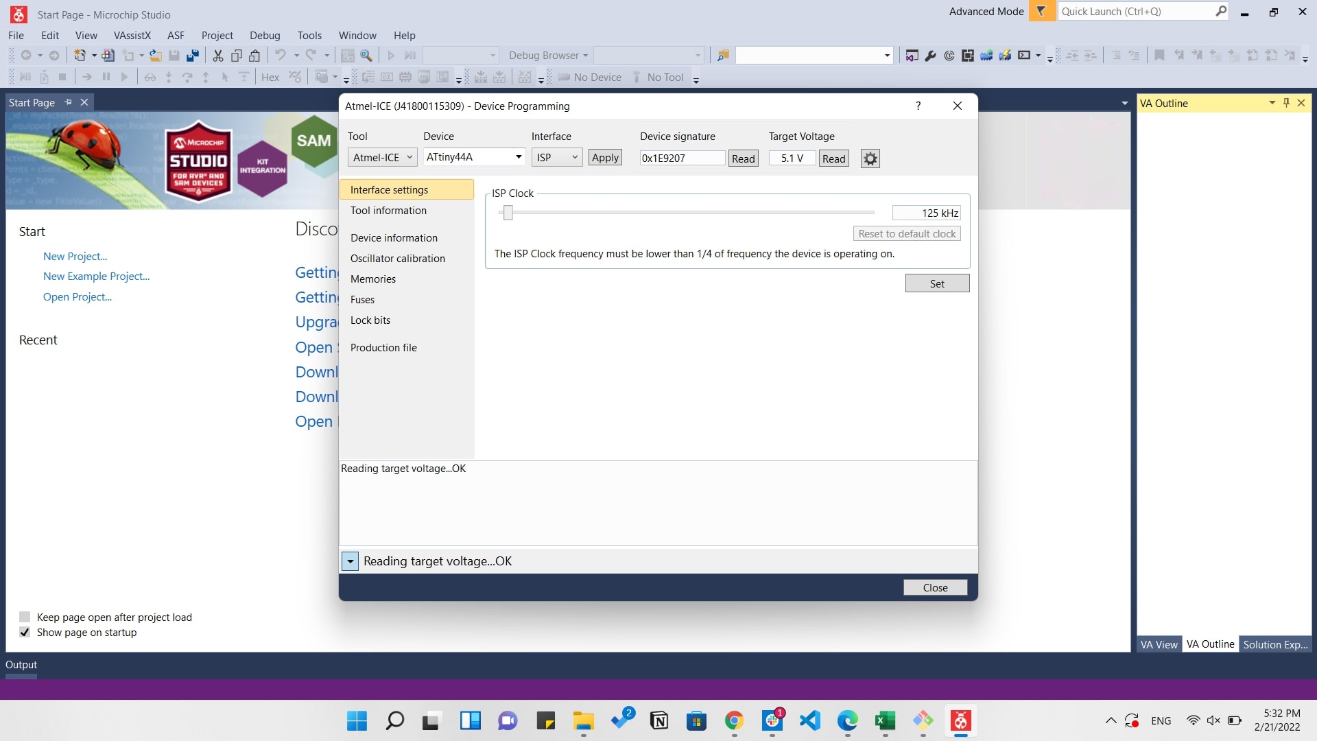
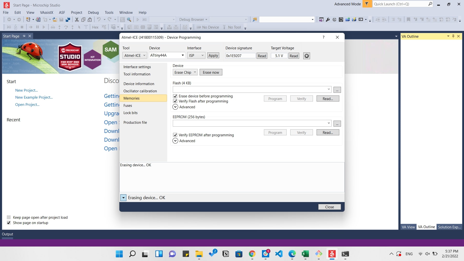
After that just click on Program to start programming the board.
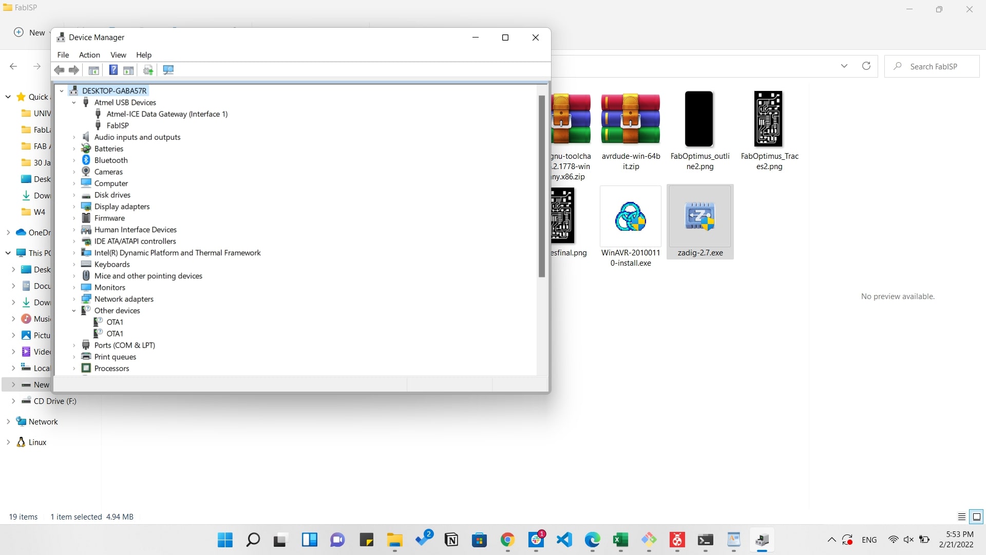
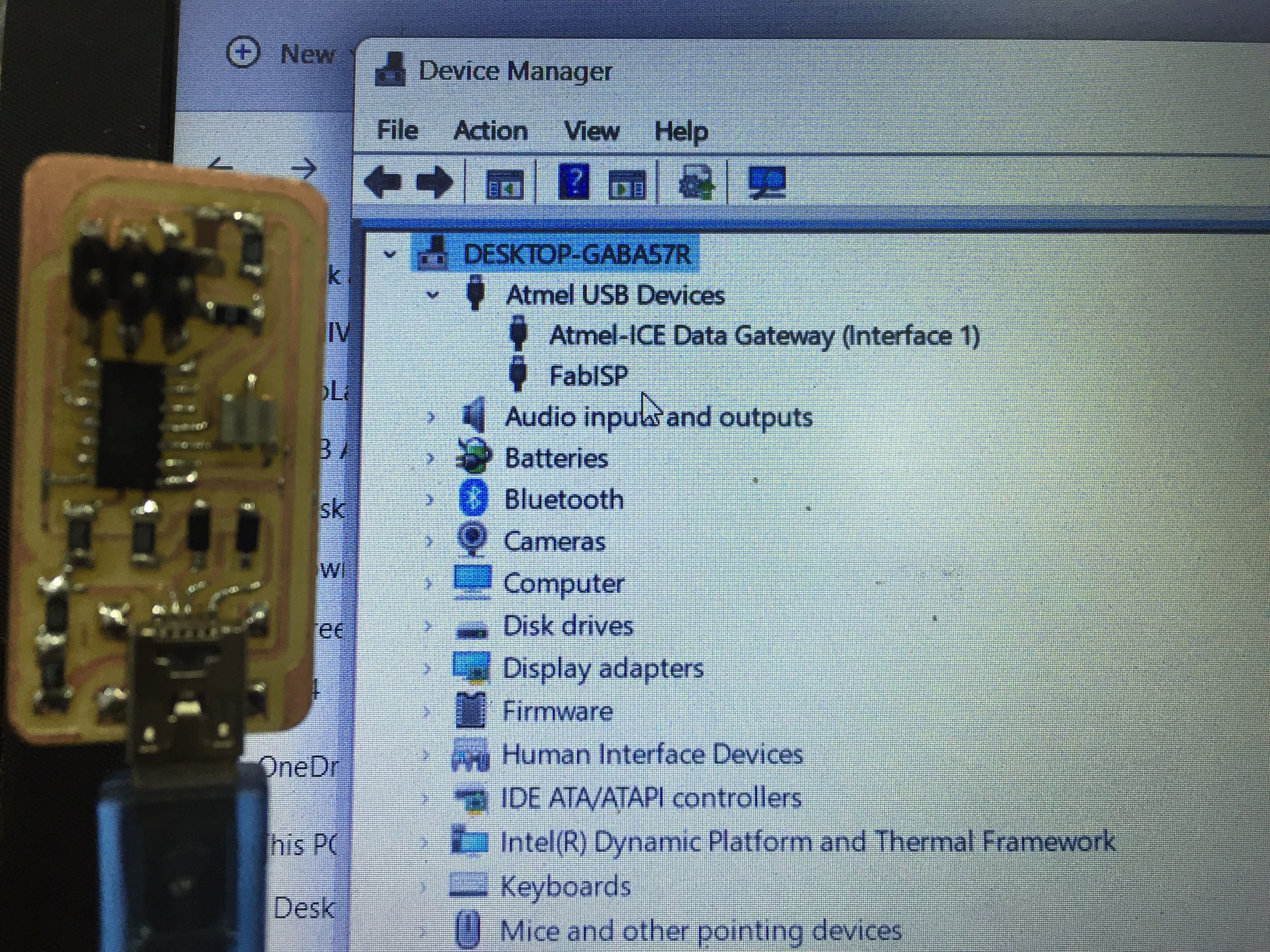
Hooooray! now it's available on the device manager as a programmer.
The final step is that once we have the board programmed, we want to disable the possibility of an external device reprogramming it. By severing the connection between RST and RESET, 0V can never be applied to the reset pin, and therefore our board cannot be reprogrammed.
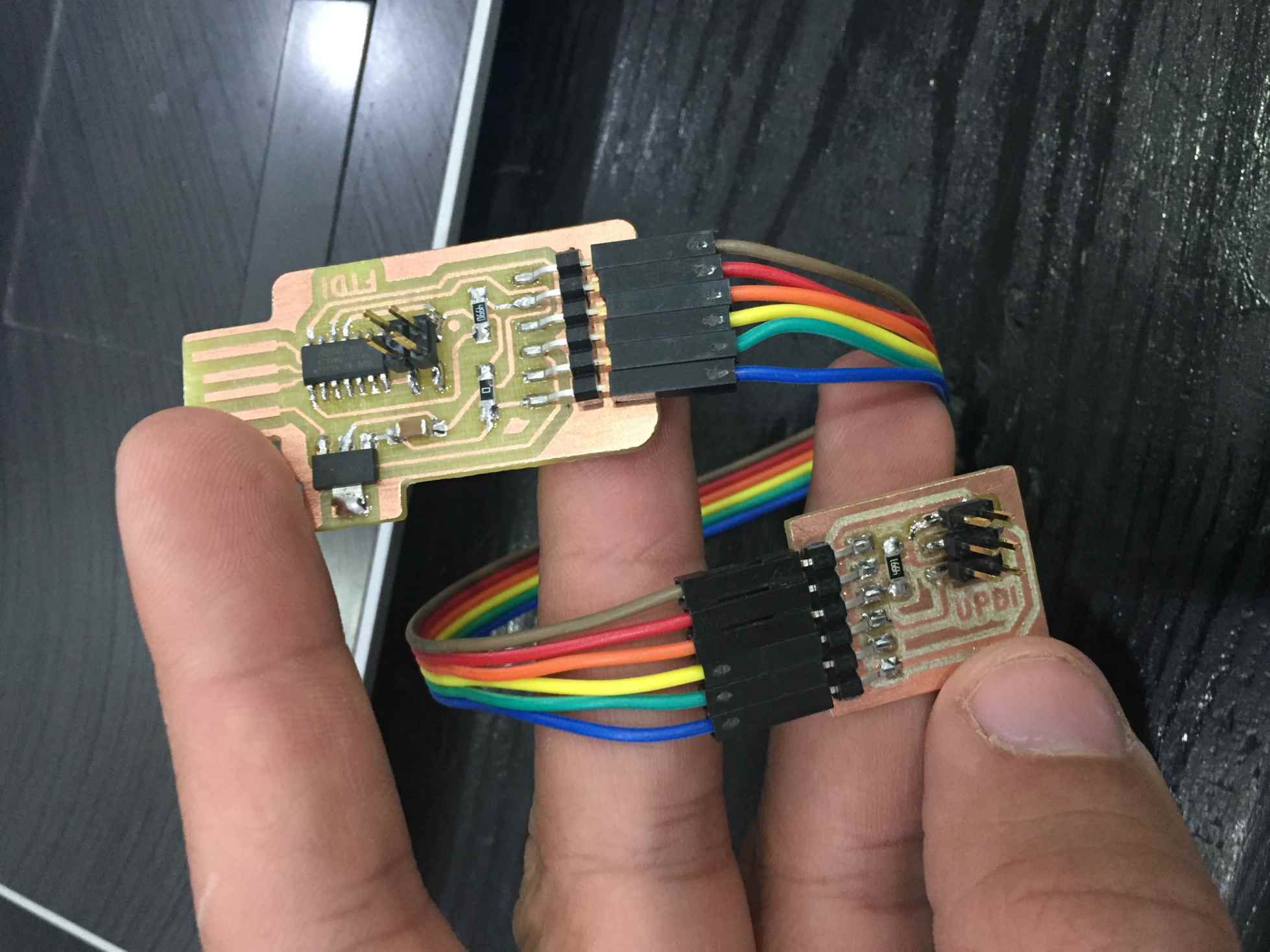
UPDI Programmer
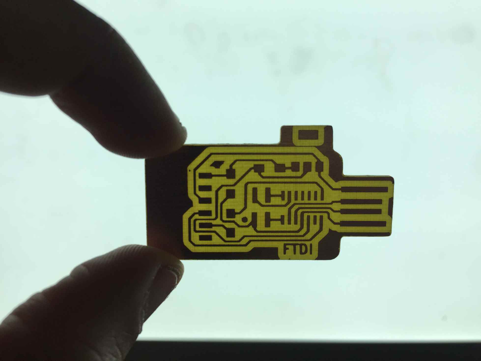
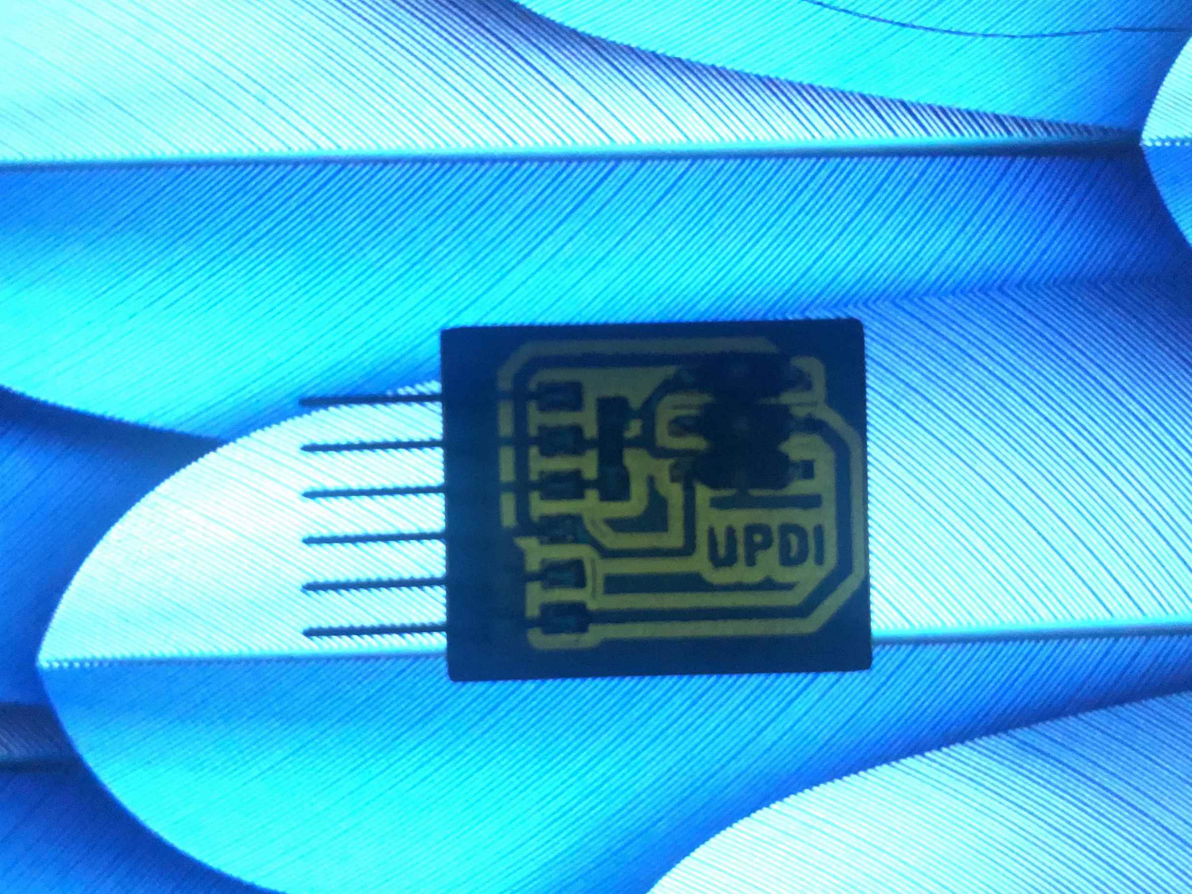
After the success of the FABISP I decided to make a UPDI programmer as I knew that it has only 3 pinouts to program the MCU instead of 6 as the ISP. So the board was made by Krisjanis Rijnieks that you can find here: Bridge serial D11C
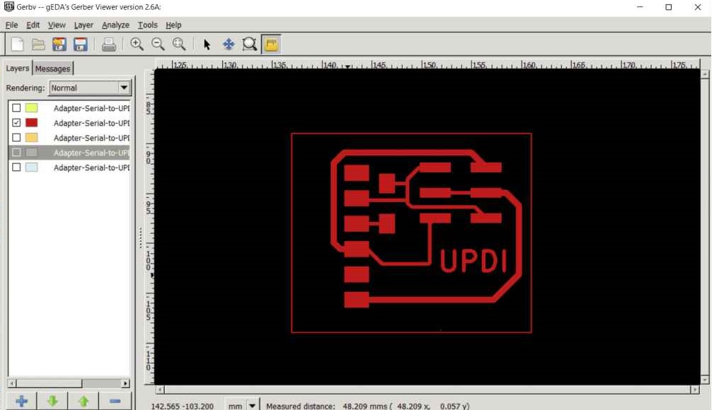
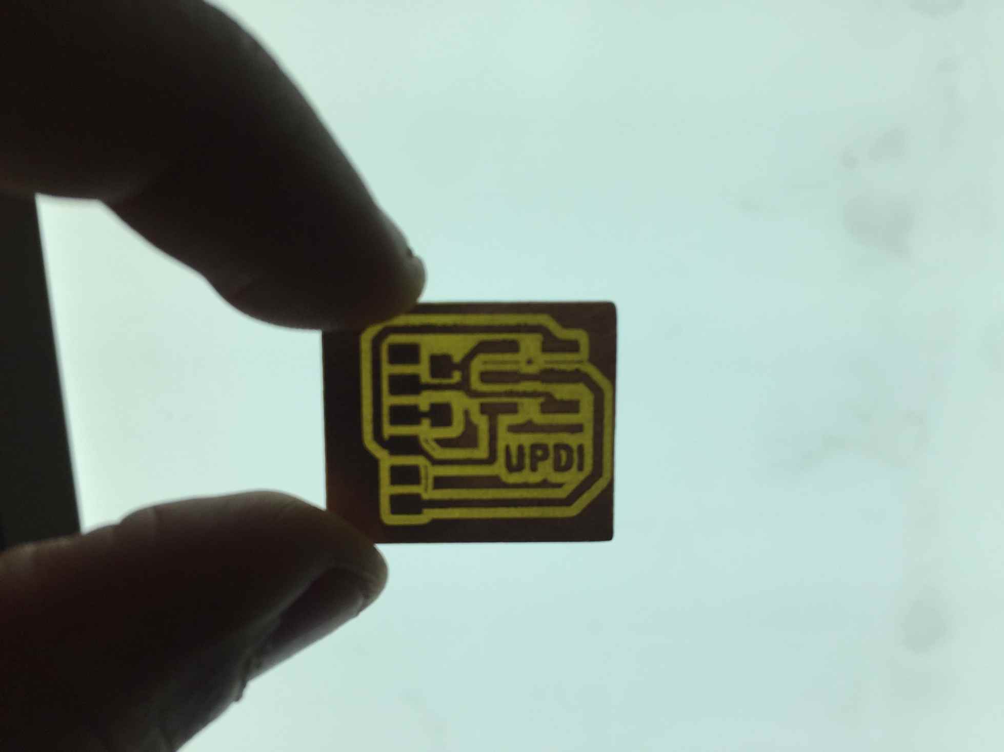
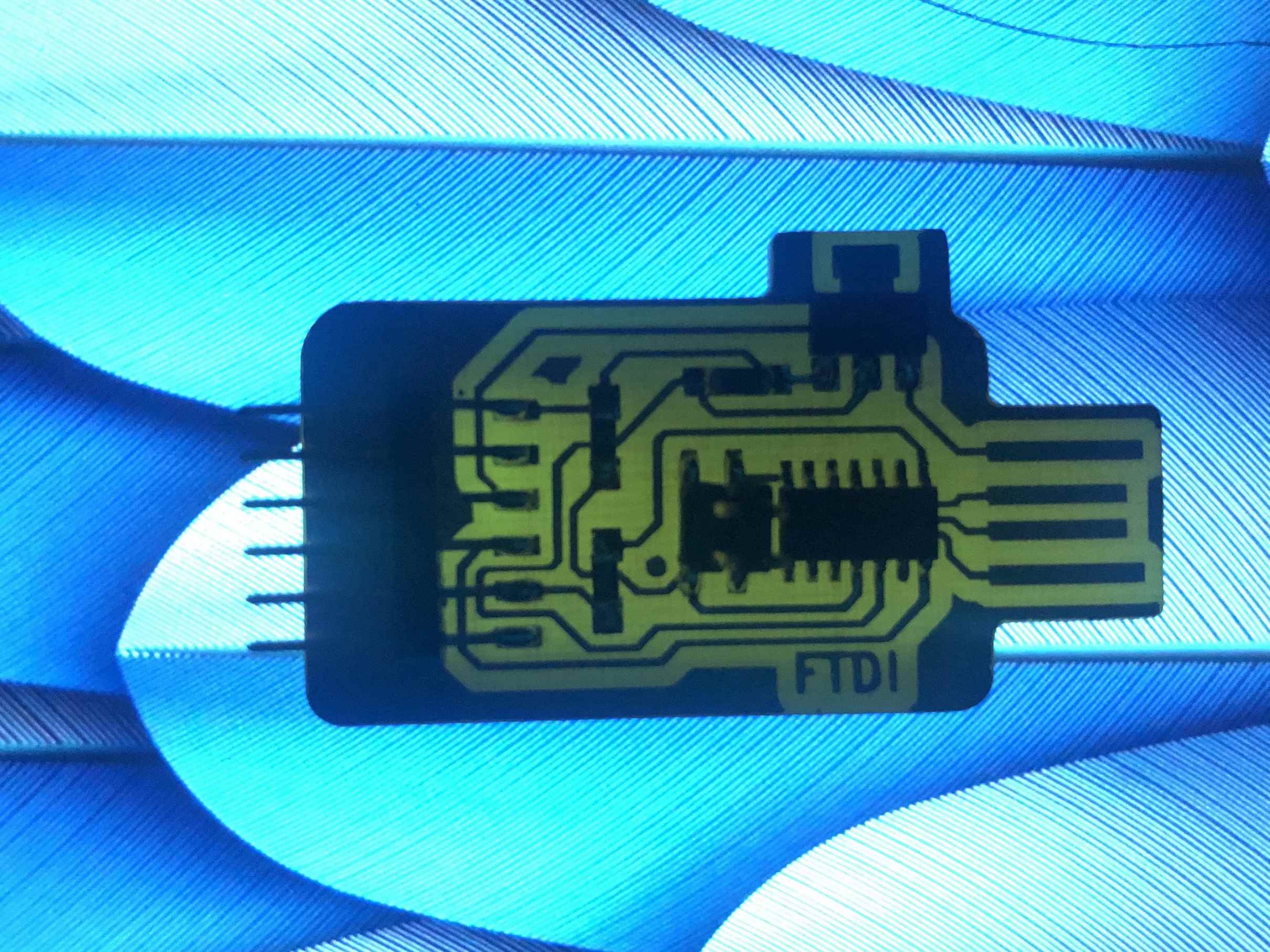
But this programmer has an FTDI output and we need the UPDI output so he also made the converter used with it found here: Programmer Adapter Serial to UPDI
After downloading the files I exported the PNGs used for the milling process from Gerbv.
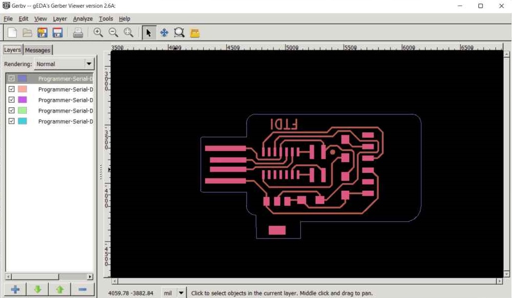
Then I started milling that on the Modella machine.
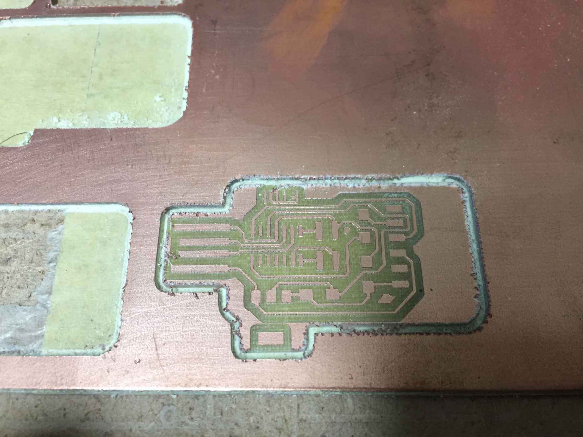
After that was the soldering, I had to solder the UPDI programmer and the converter, but Unfortunately I soldered male FTDI pin headers but I managed to change them later to female ones to be able to connect the converter easily.
Them components were simple as following.
| Name | Description | QTY |
|---|---|---|
| ATSAMD11C14A Microcontroller | ATSAMD11C14A | 1 |
| Voltage regulator | LM3480 Linear Voltage Regulators | 1 |
| 1uF Capacitor | Capacitor | 1 |
| 4.99k ohm Resistor | Resistor | 1 |
| PinHeader 2x02 P2.54mm Vertical | Pin header | 1 |
| Socket FTDI 01x06 P2.54mm Horizontal | Connector | 1 |
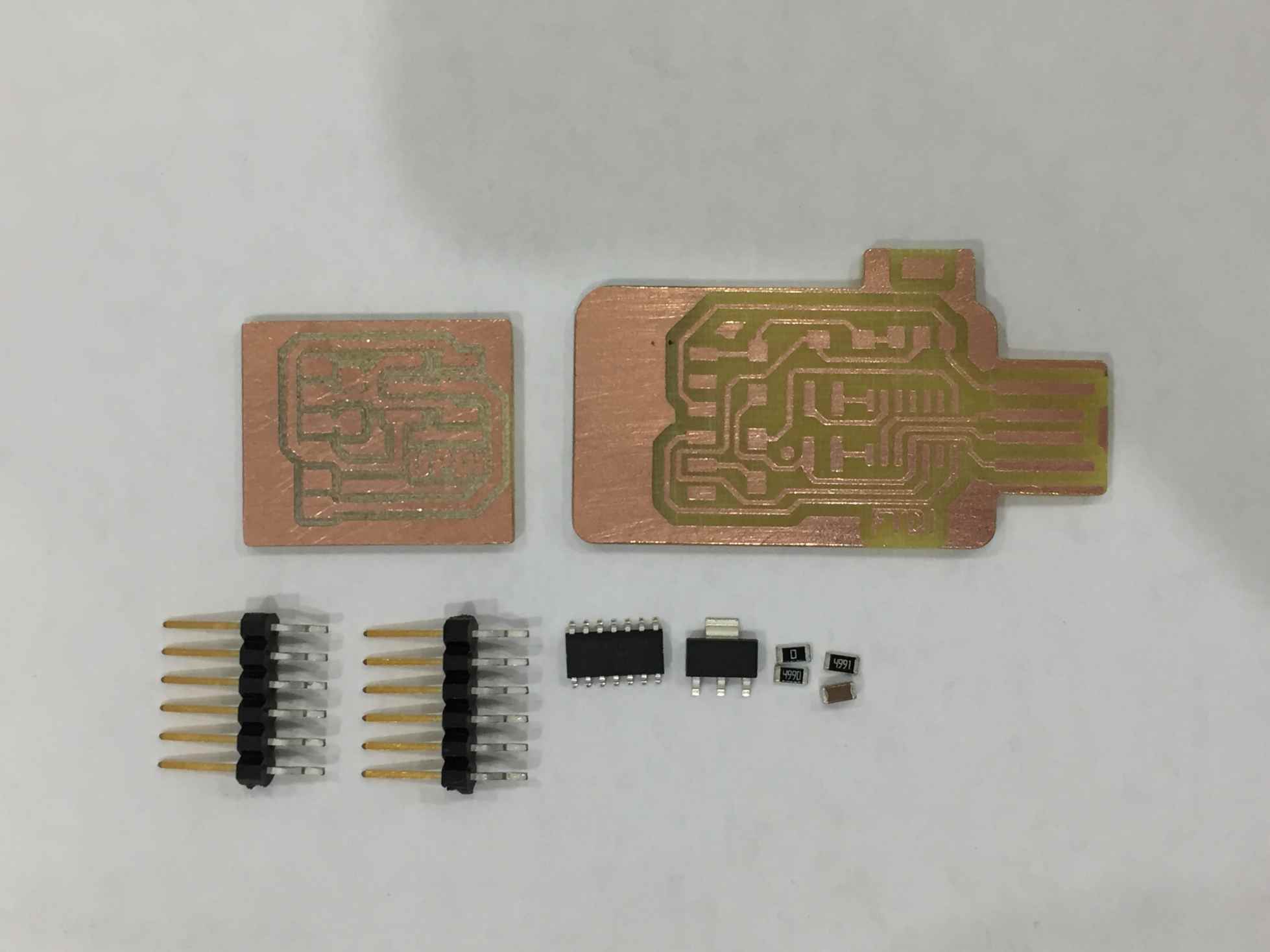
Then I worked on soldering them.
And this was the output.
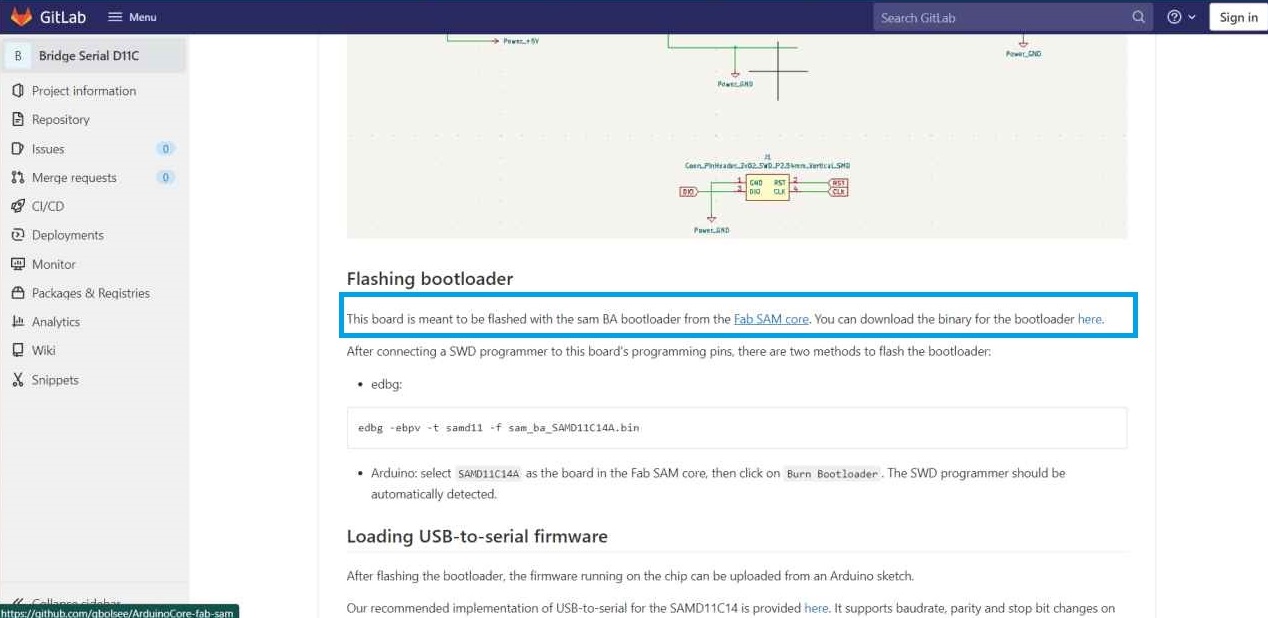
Now we need to program it to be a programmer.
I followed the great documentation Krisjanis did to use it as a programmer.
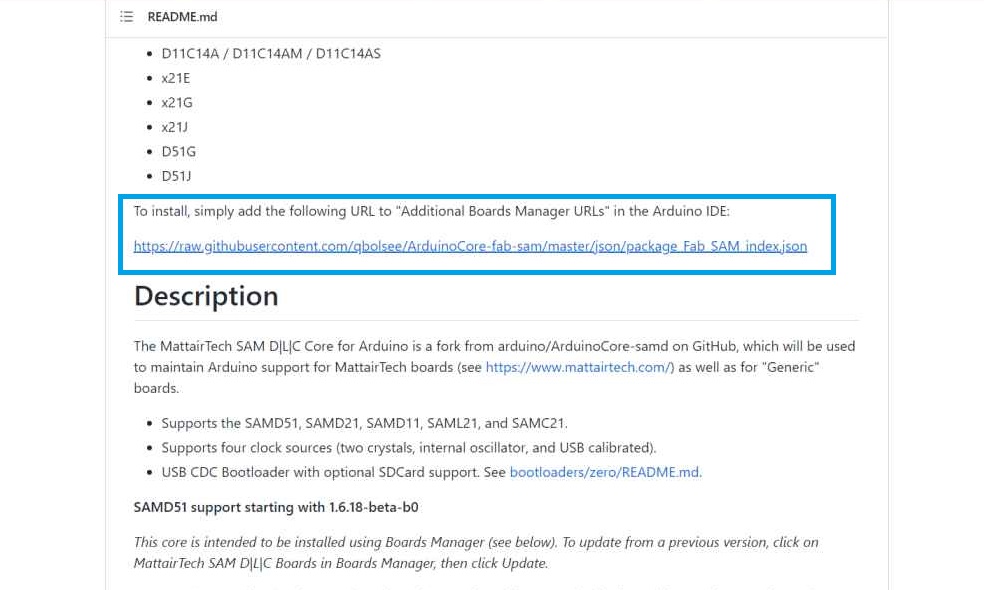
So first of all we will visit ArduinoCore from the same github page of Kris'.
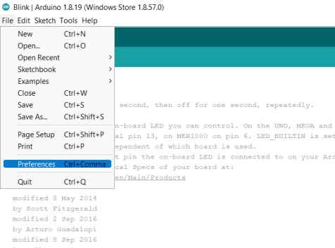
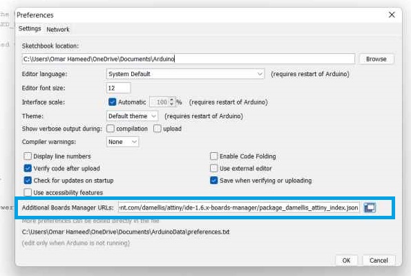
Then by copying the URL found and pasting it in the Additional boards manager URLs found in File>Preferences
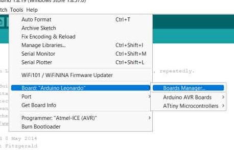
Then we need to find our board in the boards manager. So by going to Tools>Board>Boards Manager search for Fab SAM core for Arduino by Fab Foundation.
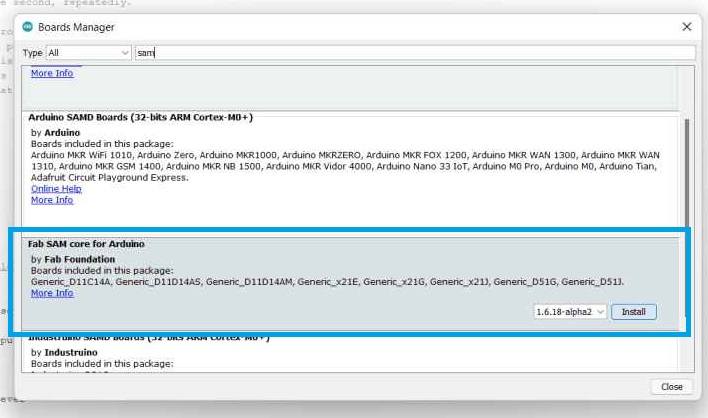
After installing it, I went to check if it's available and I successfully found it installed.
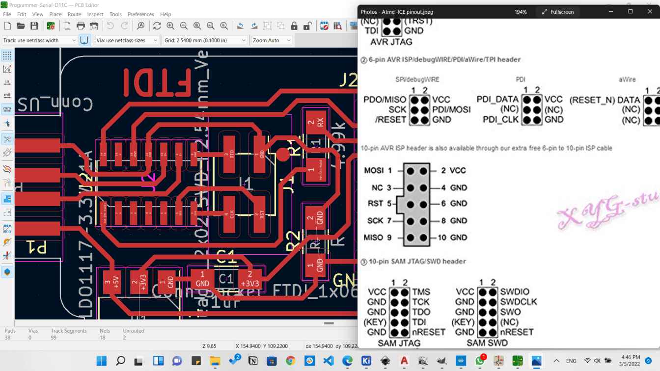
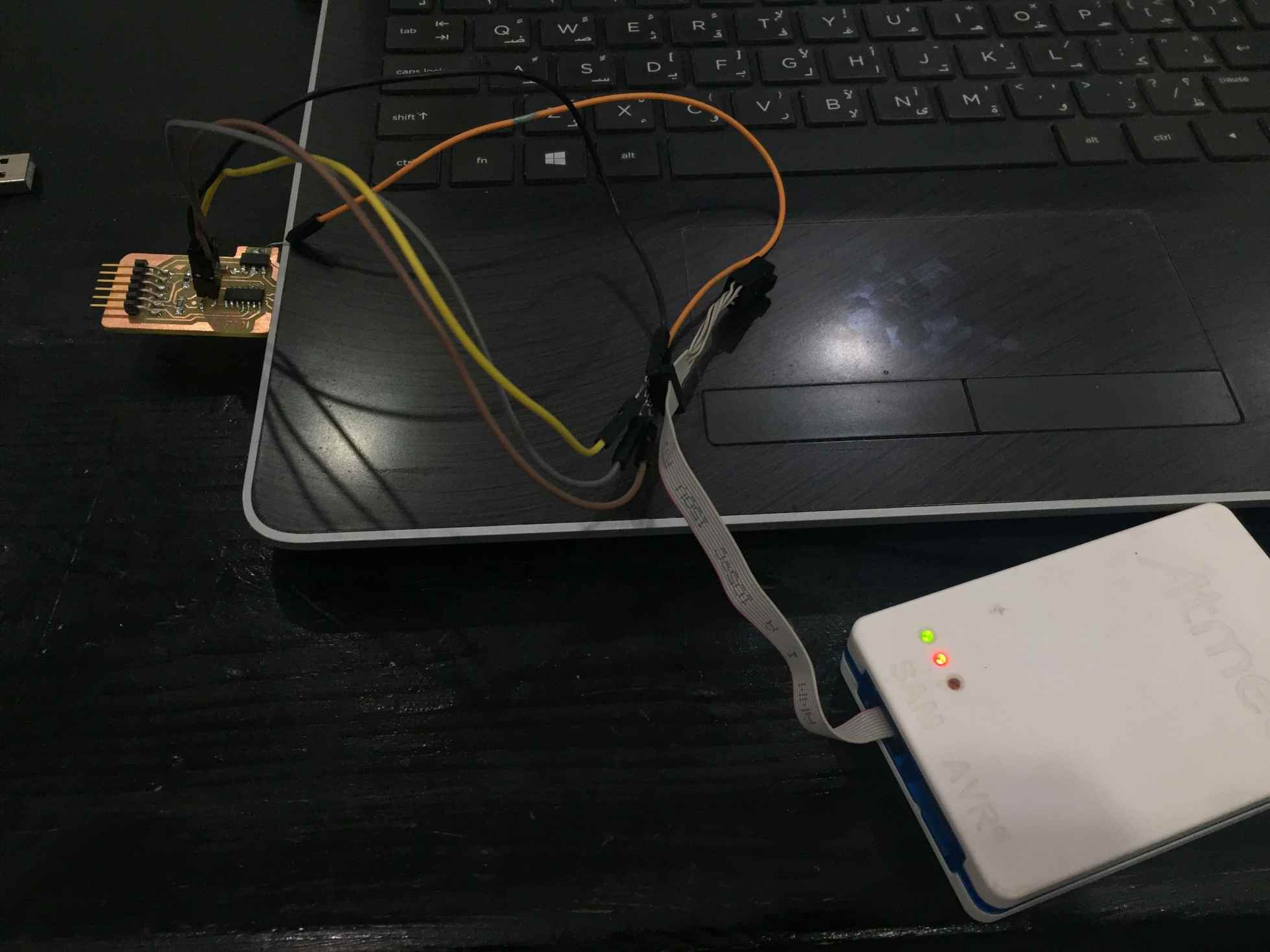
Now I need to burn the Bootloader. So I connected the Atmel-ICE programmer to the UPDI according to the following map.
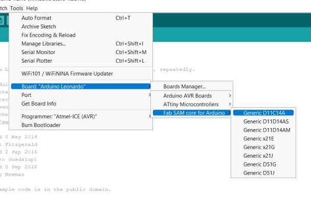
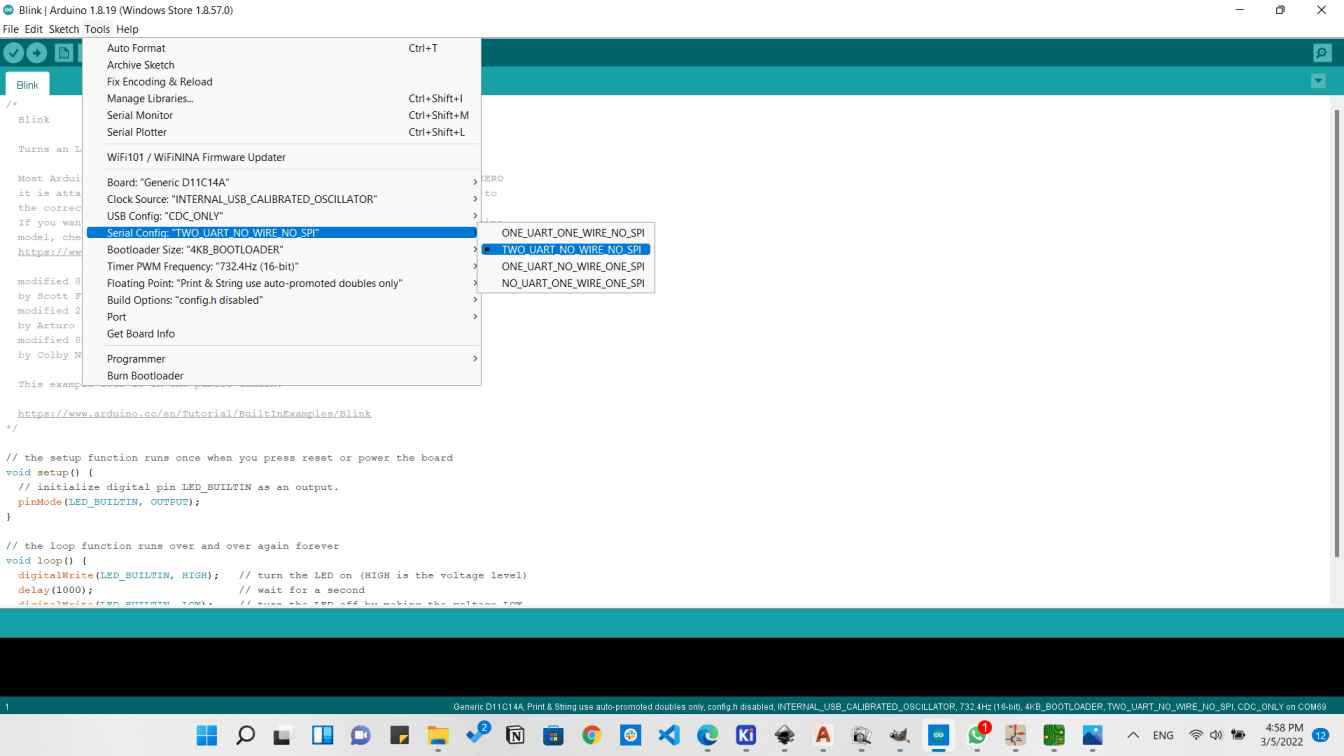
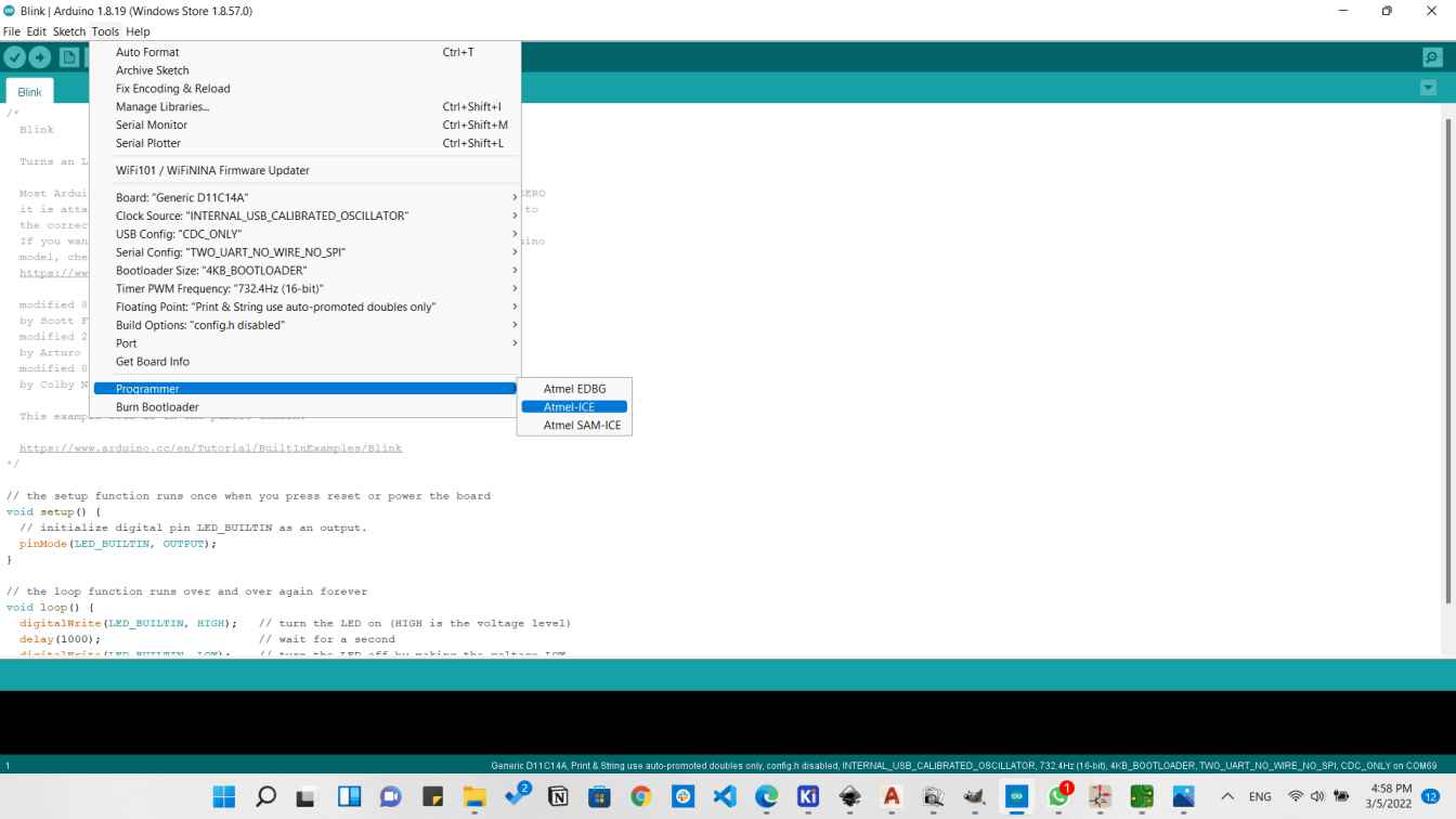
We have to set the following:
- Board Generic D11C14A
- Serial Config TWO_UART_NO_WIRE_NO_SPI
- Programmer Atmel-ICE
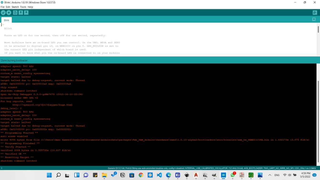
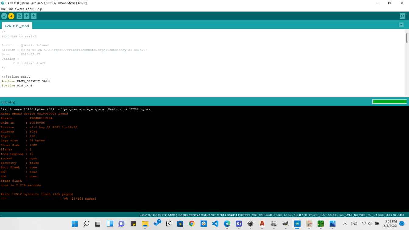
After burning the bootloader we need to upload the Firmware using Ardiuno IDE but this time without the Atmel-ICE We can upload that directly using the USB in the UPDI programmer.
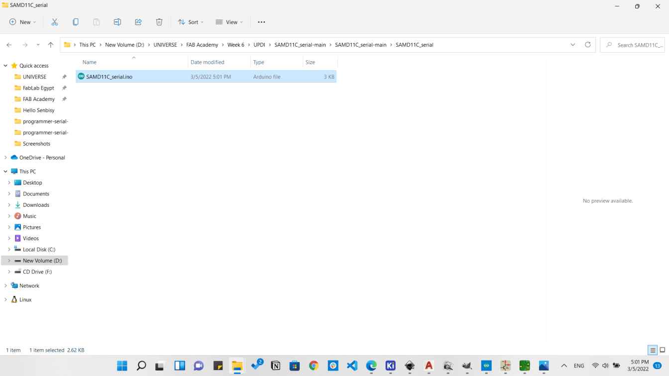
So by going to Quentin's SAMD11C_Serial
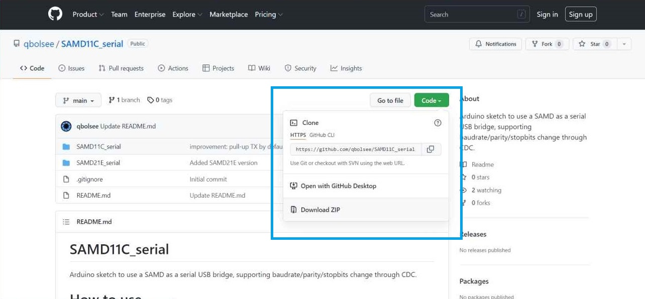
Then I downloaded the code found there which is the firmware we should burn to our programmer.
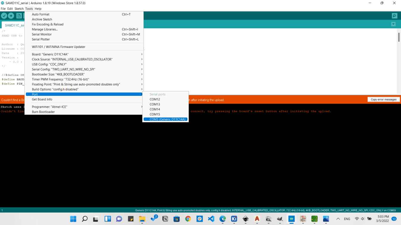
We will just need to choose the Port here which will be defined as Generic:D11C14A
Then click on Upload
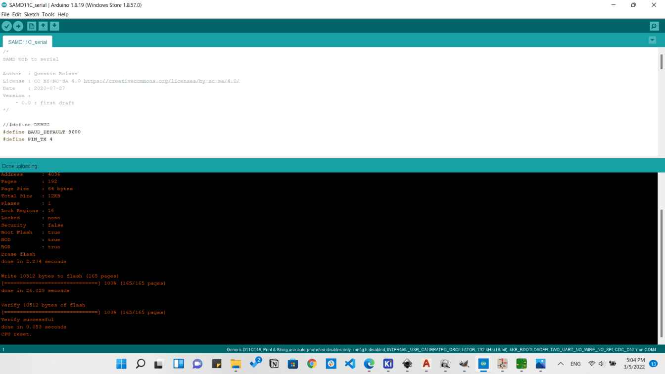
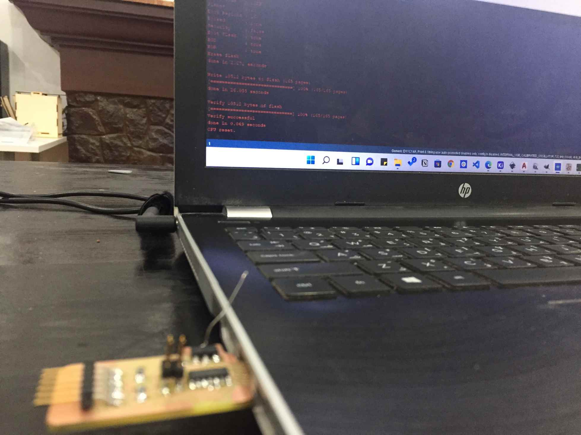
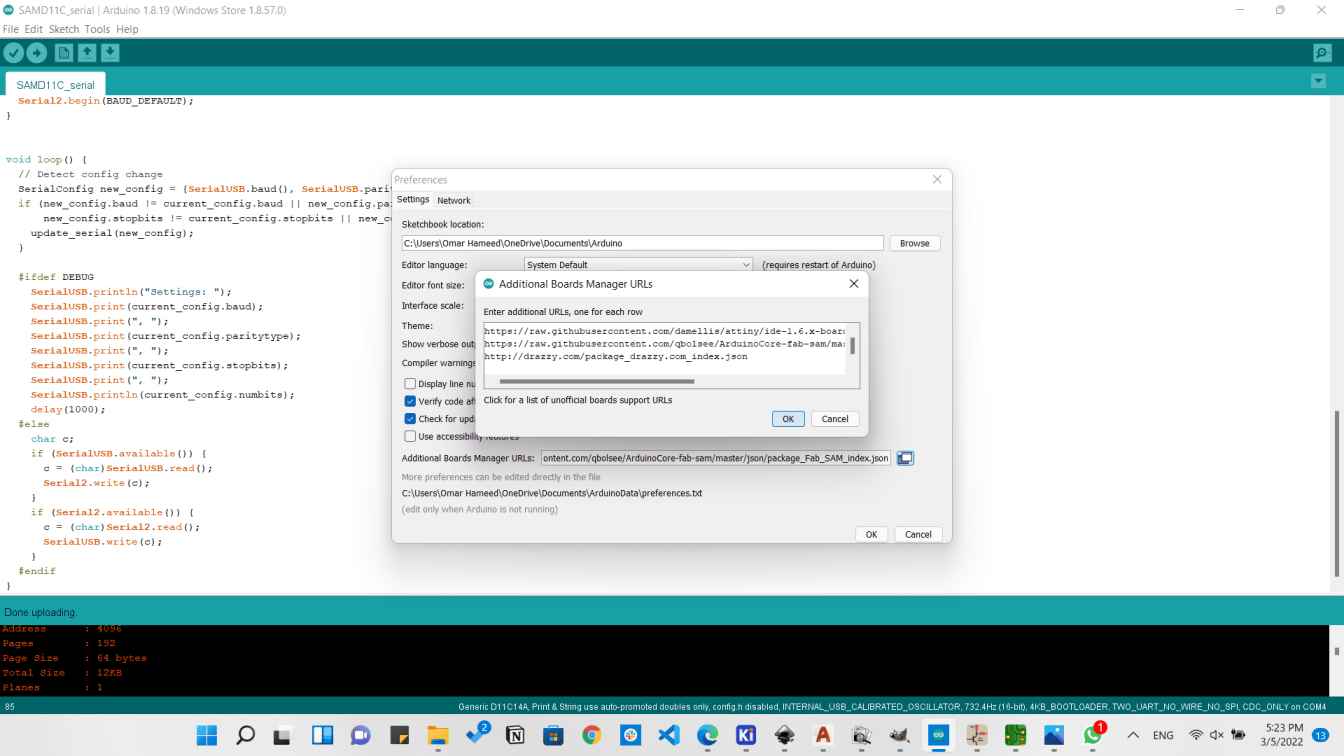
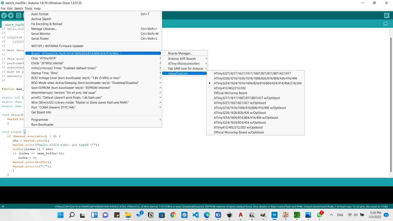
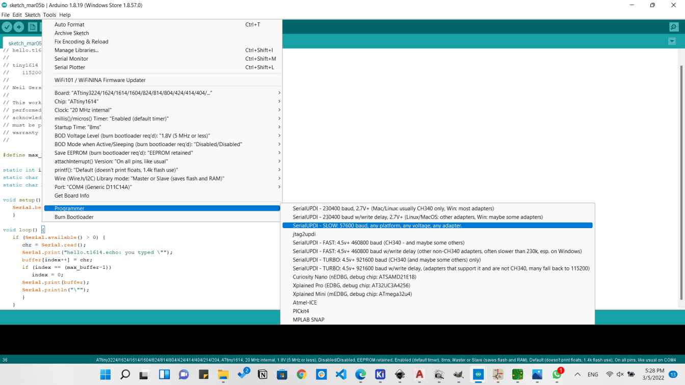
Now the Firmware is uploaded successfully. But we need to test it if it's working or not, so I will install the megaTinyCore in order to be able to use it. So I went to Spence Konde copied the URL for the board.
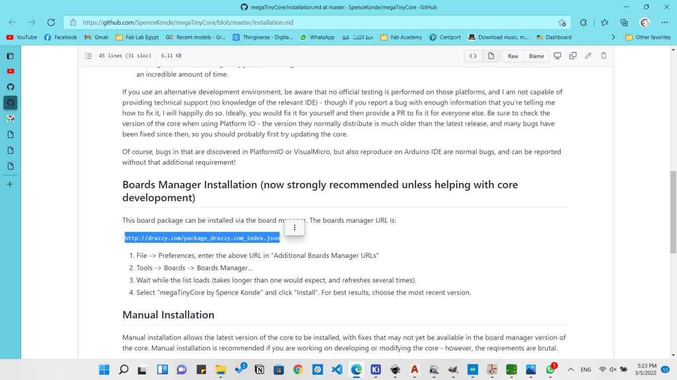
And pasted it in the additional boards manager.
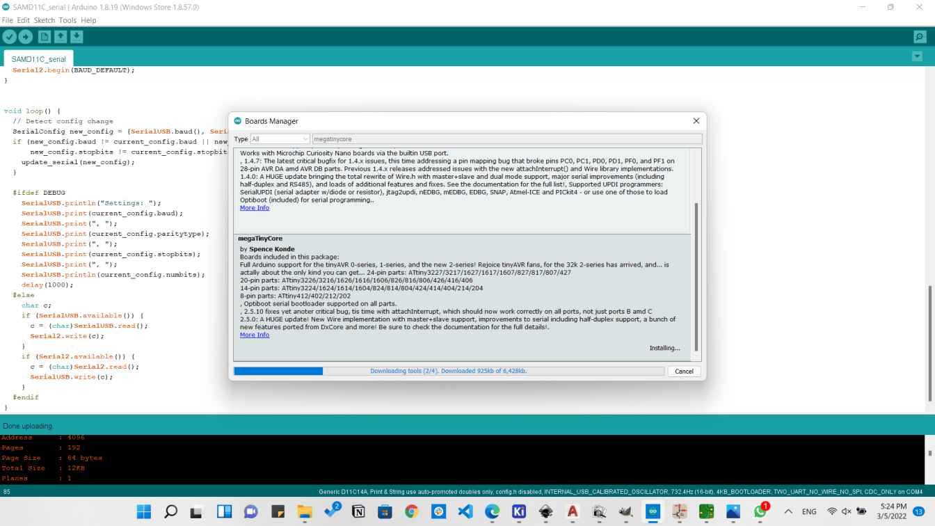
Then I downloaded the megaTinyCore made by Spence Konde from the boards manager.
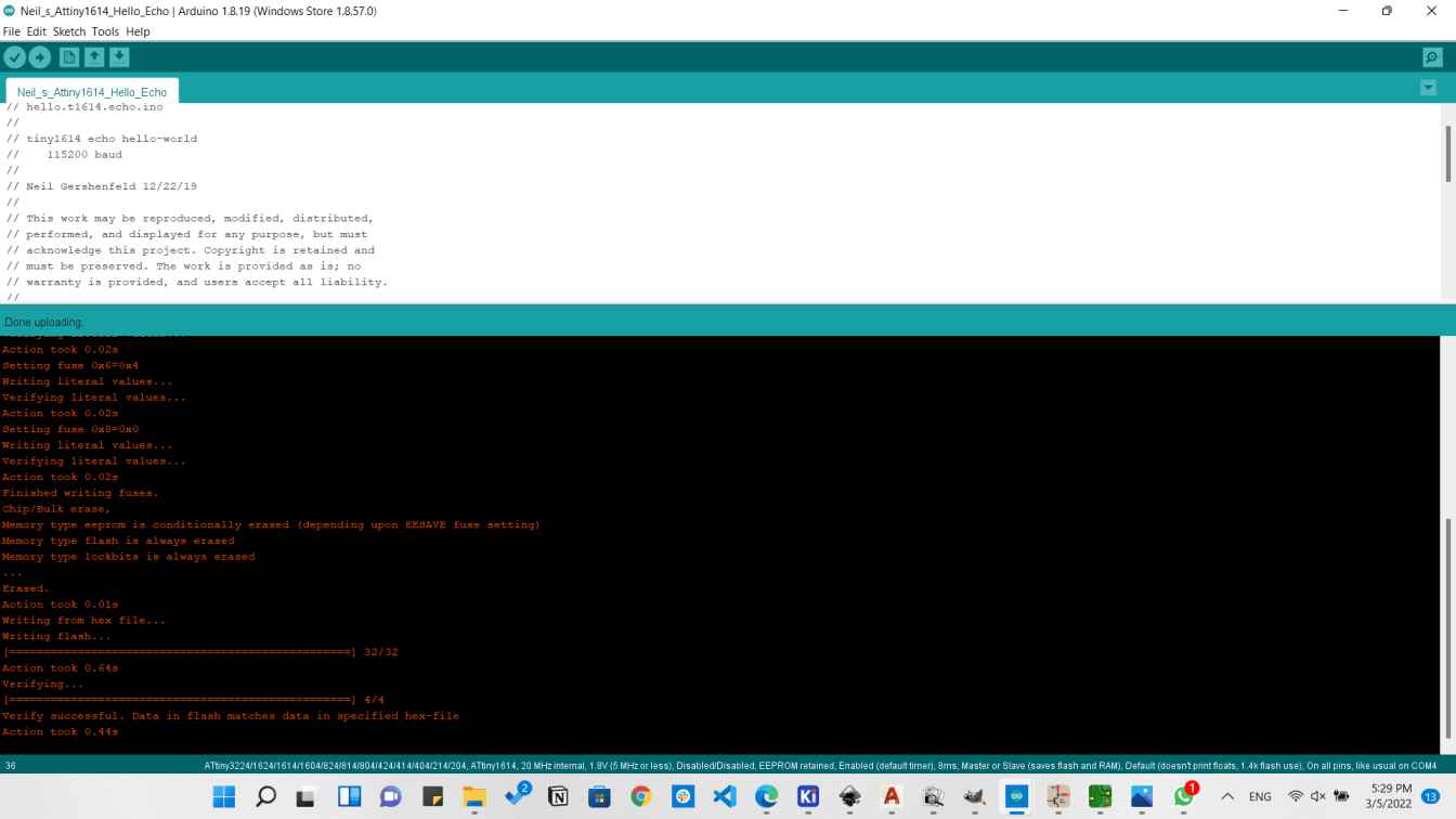
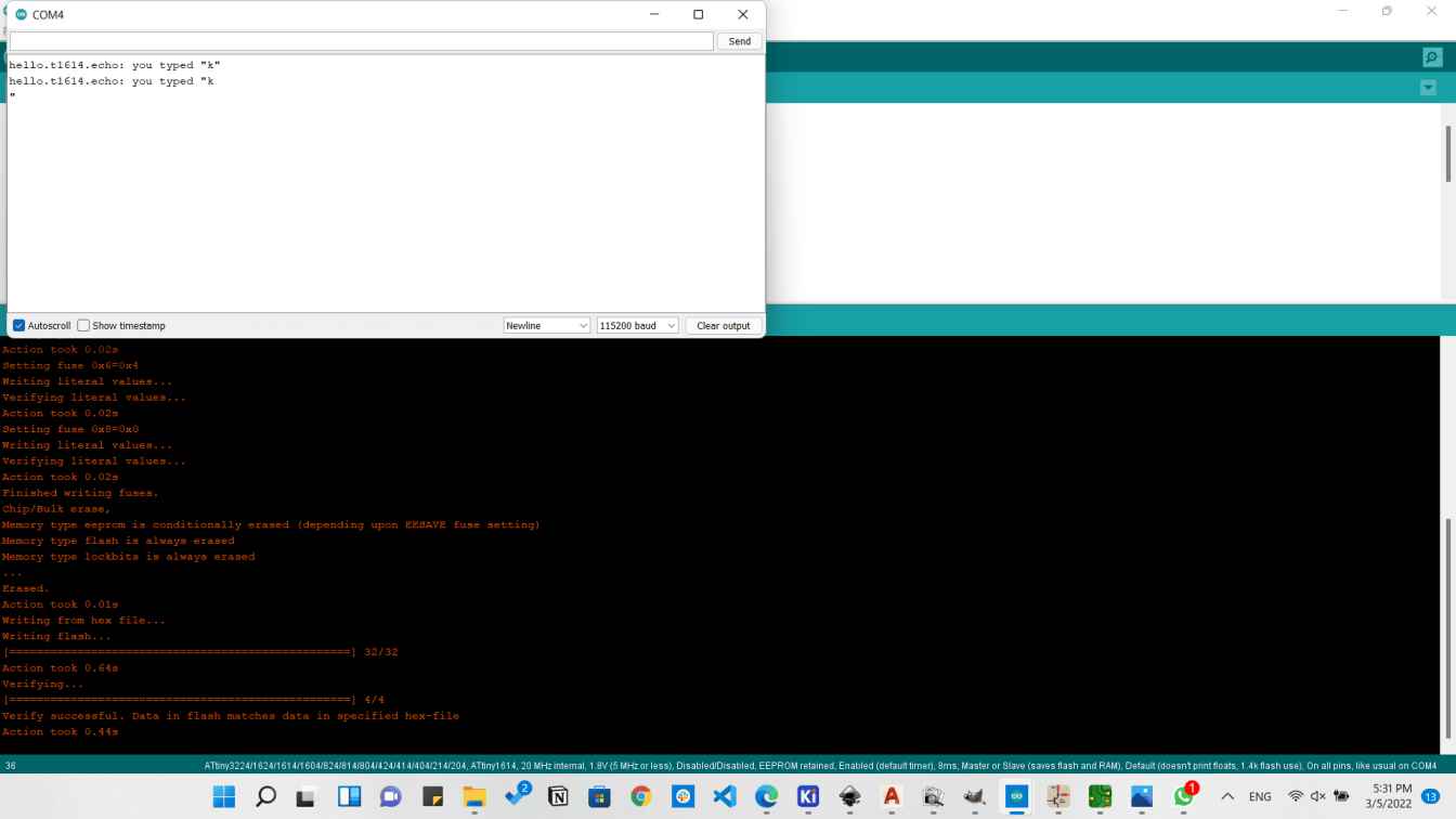
Then I copied the test code Neil have written and chose the tools shown below. Hello1614
Then I tested that and it worked perfectly
Downloads
Another weak I survived!!