Week 9 Molding and Casting

Assignments:

Group assignment:

    • Review the safety data sheets for each of your molding and casting materials, then make and compare test casts with each of them.

Individual assignment:

    • Design a mold around the stock and tooling that you’ll be using.
    • Mill it (rough cut + (at least) three-axis finish cut ).
    • And use it to cast parts.

Learning outcomes:

    • Design appropriate objects within the limitations of 3 axis machining.
    • Demonstrate workflows used in mold design, construction and casting.

Weekly Practices

Reasearch

For this week’s research, I found this video very helpful. I will summarize this week’s topic here:
Take Away from the session, difference and importance of molding vs 3d printing.

    • Surface finish: The 3d printing has surface finish limitation, example layer height.
    • Low cost : plastic vs wood/wax cost
    • Short run production: time and cost of material.
    • Range of materials : 3d printers have limited materials.

Flexible vs rigid :Rigid (positive) to flexible (negative) then back to rigid (cast final product)
Importance of using flexible material as negative:

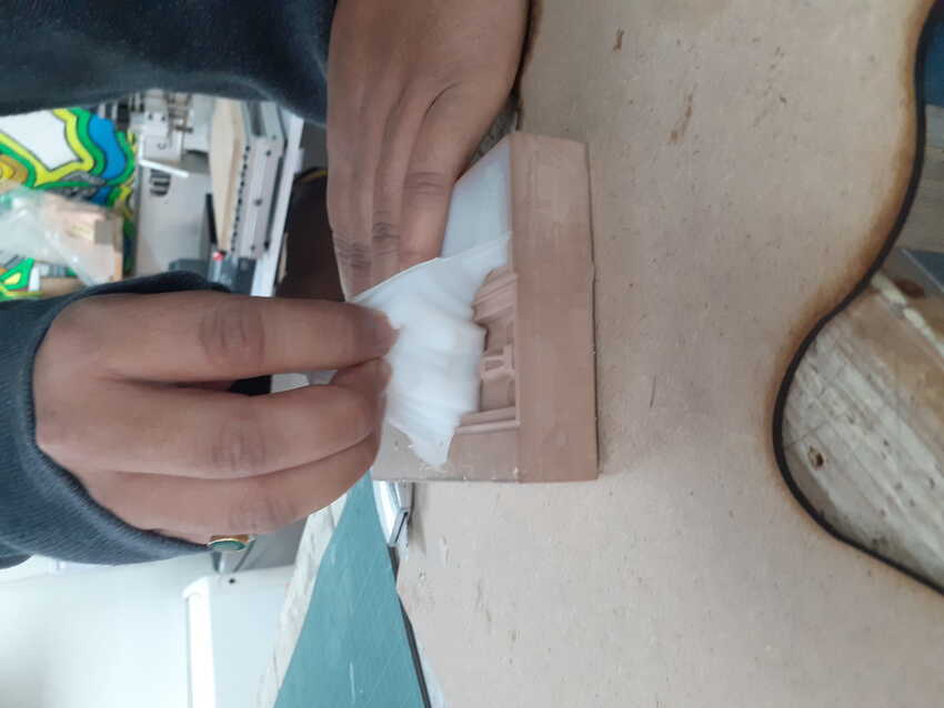
    1. Flexible to ease the process of removing
    2. Flexible to ease the process of correcting any errors
    3. Recasting is flexible to enhance the rigid mold life and recast it for more production.

Relevant terms:
Pour spouts: basically a delivery system for casting medium, importance: makes it easier, efficient, saving the material and keeping the working environment clean while casting.
Types: direct casting and in direct casting.
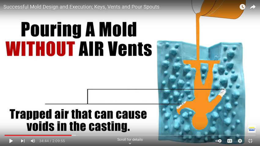
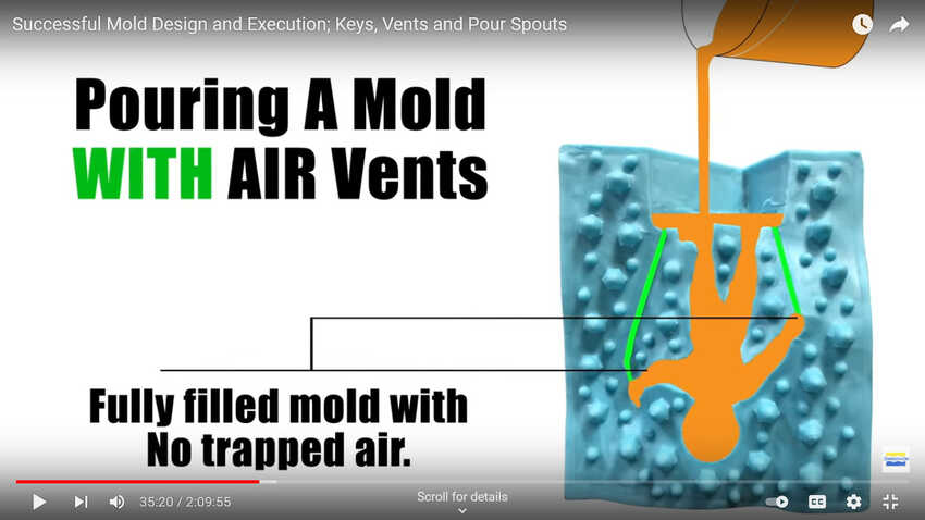
Vents: to let the air out while casting and avoiding any bubbles which damages the casting process.
Keys: register 2 part molds - to make one part connect to the other, importance: enables better casting, minimizes post processing and eliminates any flashing in casting.
Types of keys: plugged keys, orientation keys and step keys.
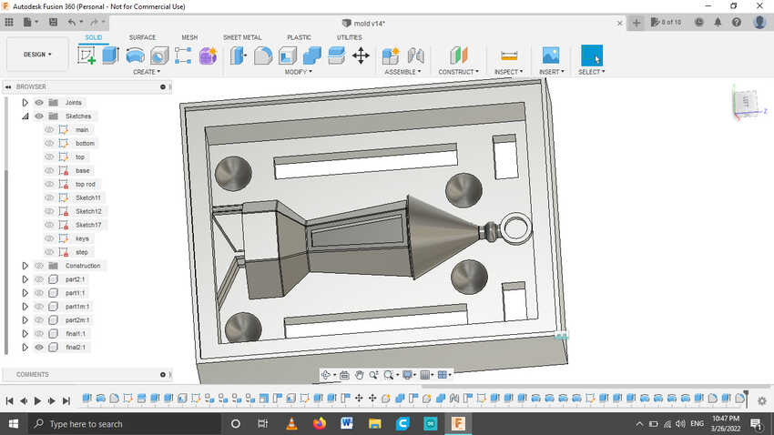
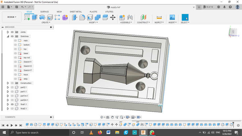
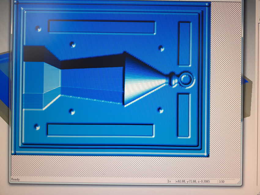
Parting Line --This is the line that will define where the two halves of the molds separate. Usually, you'll want to make sure this generates the minimal number of undercuts. Also, to make sure the two halves of the mold align nicely.
Undercut: In manufacturing, an undercut is a special type of recessed surface that is inaccessible using a straight tool. In turning, it refers to a recess in a diameter generally on the inside diameter of the part. In milling, it refers to a feature which is not visible when the part is viewed from the spindle. In molding, it refers to a feature that cannot be molded using only a single pull mold. In printed circuit board construction, it refers to the portion of the copper that is etched away under the photoresist.
Tips:
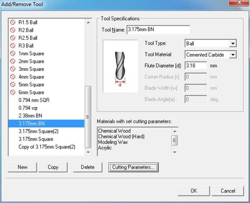
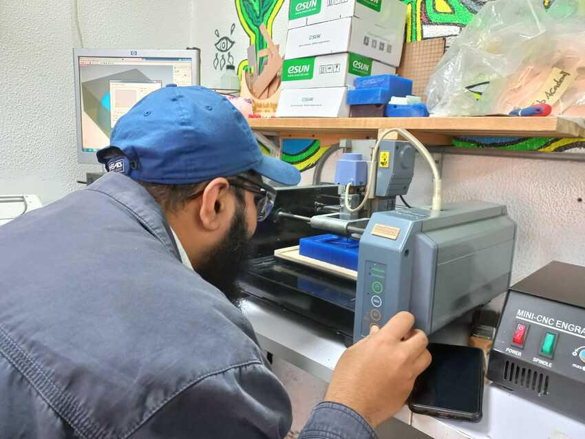
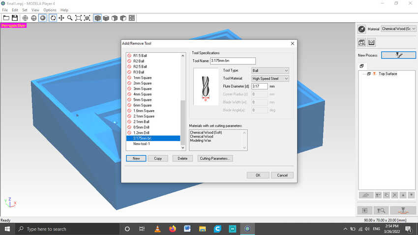
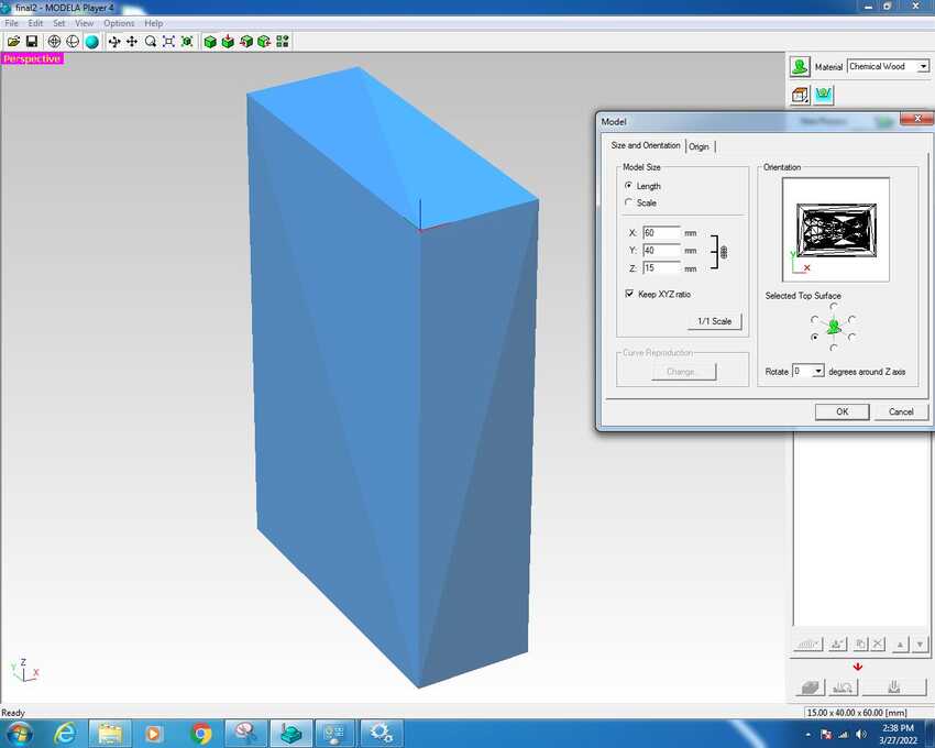
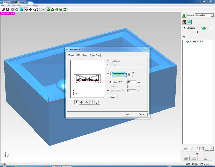
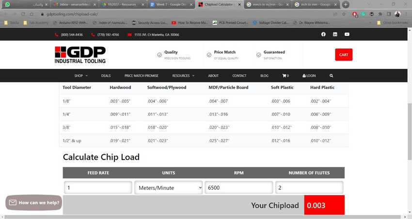
Before designing: mold stock measurements plus tool diameter - check cut depth to avoid colliding the tool or its holder to the part
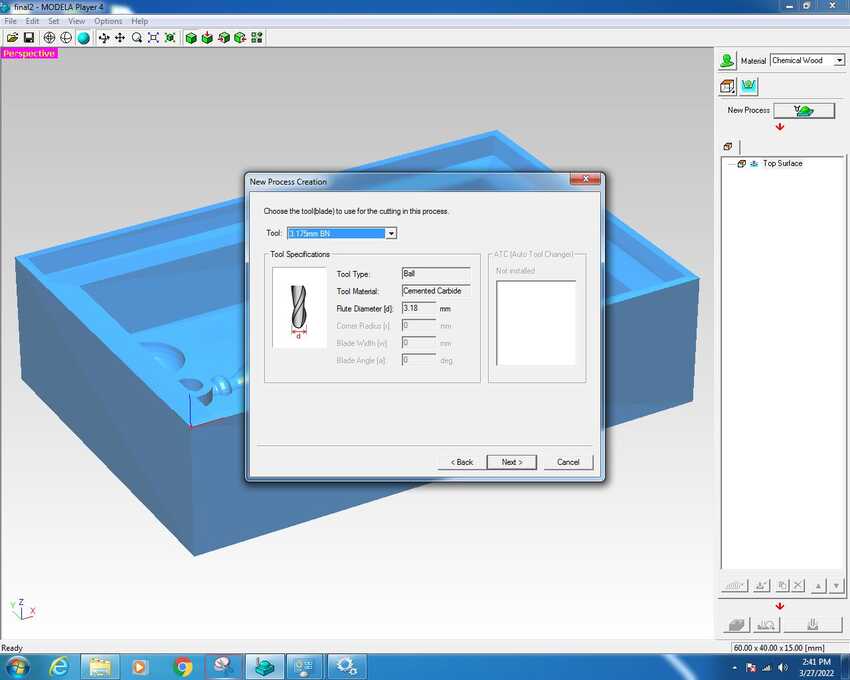
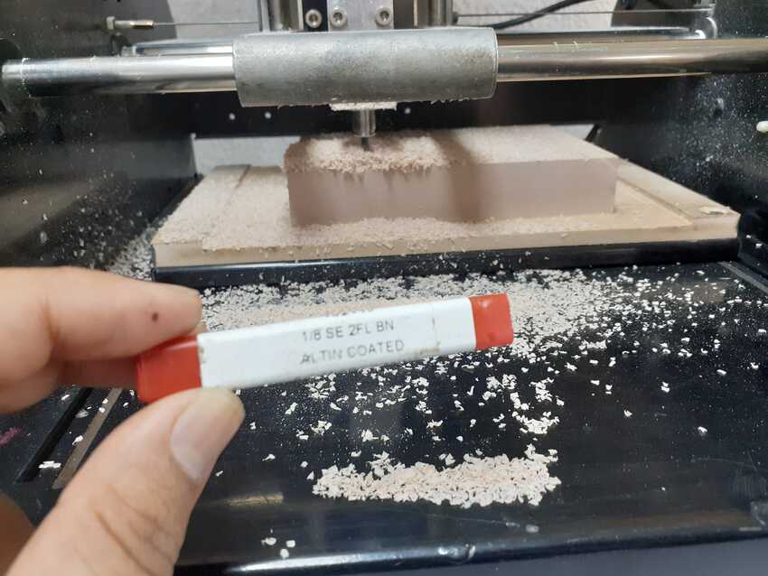
Also: Smaller diameter bits have shorter cutting depths. (for a finer cut)
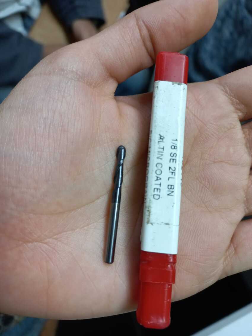
Larger diameter bits (1/8") - standard size used in the fab modules - has a longer shank and can reach deeper into the wax. (for a rougher cut)
For curvy models - use ball nose bits
For mostly flat parts / straight angles - use end mill bits
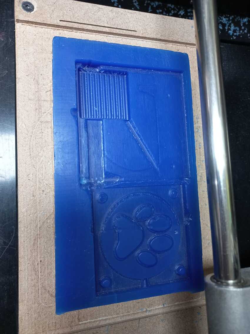
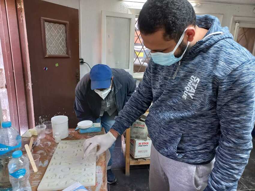
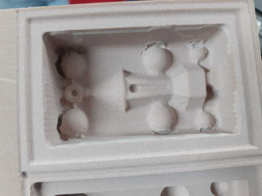
Golden rule: the cleaner the molding the cleaner the casting.
Practical tips: mixing technique while stirring scrape from bottom and sides.
Designing the wall should be higher than the design
Make thick walls if using a two sided mold.
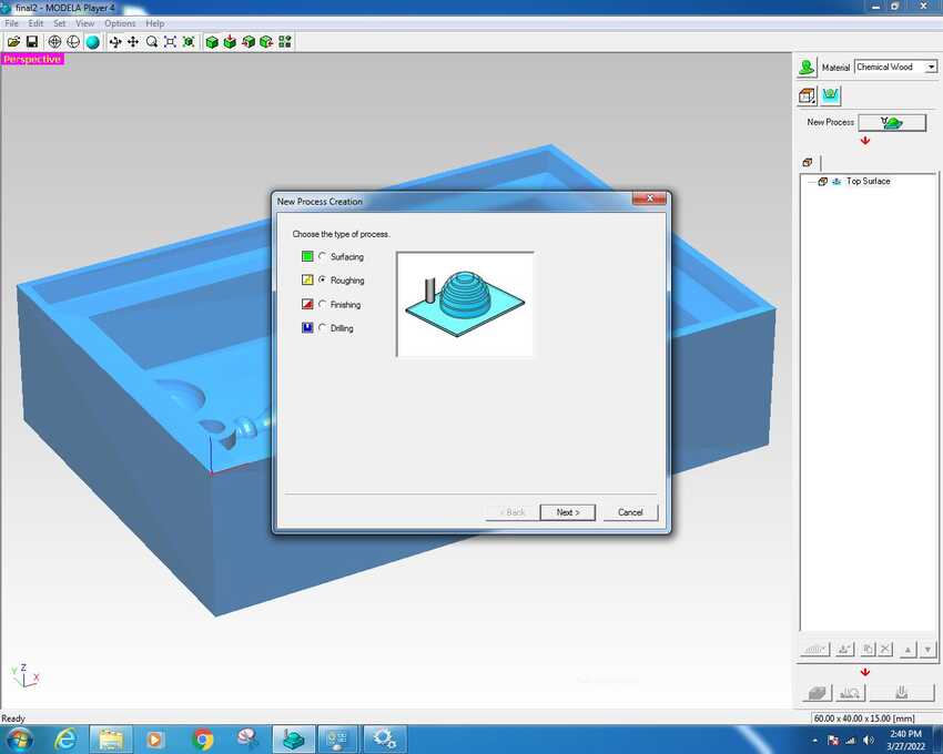
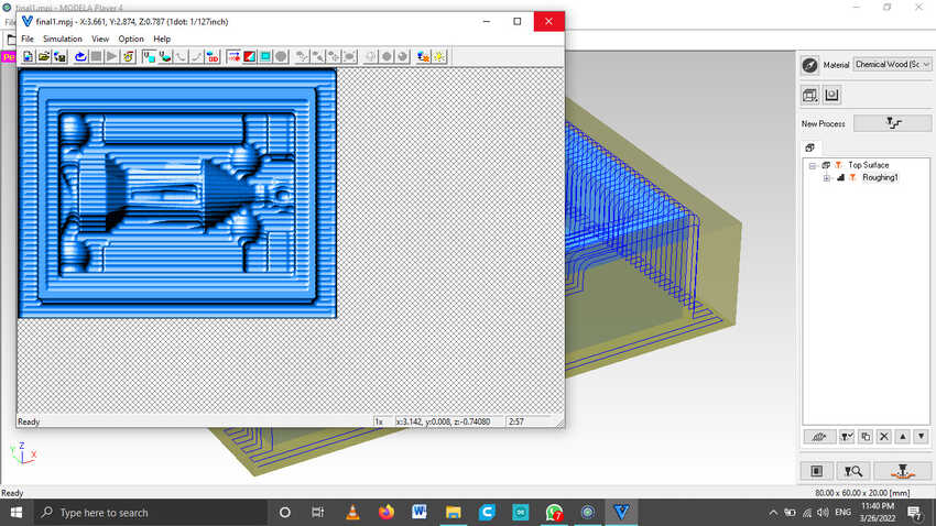
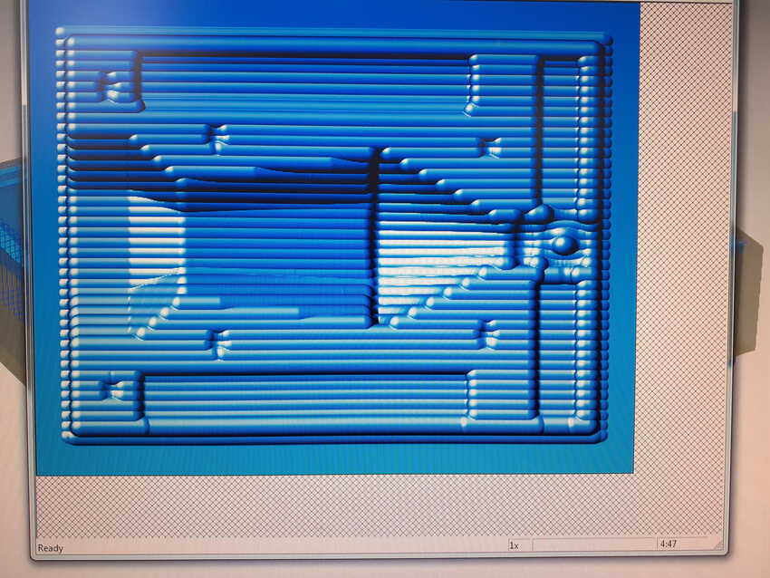
Don't forget that complex geometry will generate complex tool paths. Complex tool paths can take a very long time.
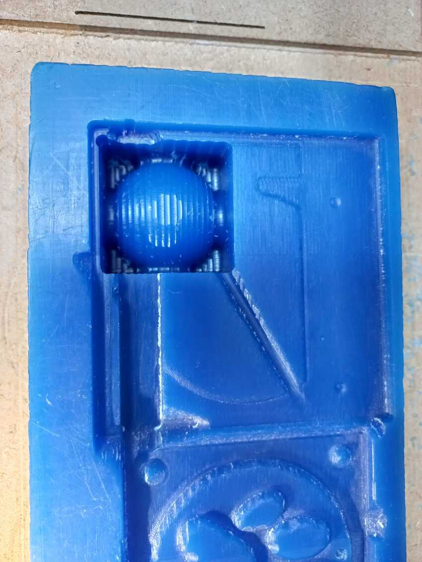
Be aware! It seems that bubbles form at right angles. Keep this in mind during design. Also, lots of 'local minimum' (aka lots of different dips and valleys) probably lend themselves to bubbles.
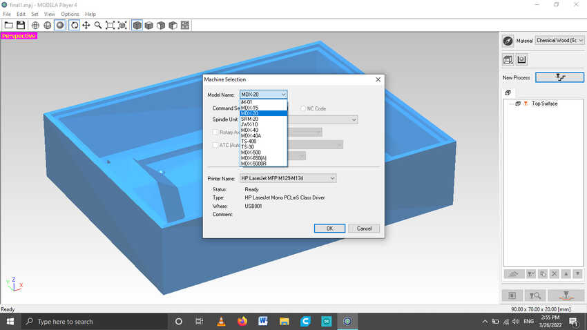
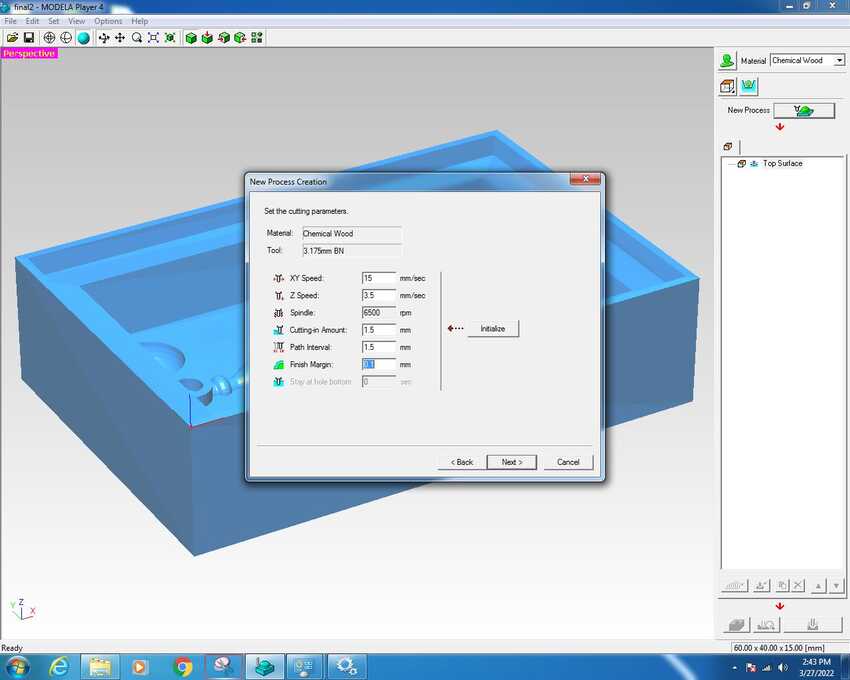
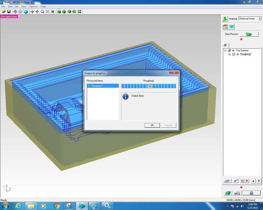
Machining: Zero out your Z axis to the top of the wax. Stop when a few shavings of wax come up. Starting at zero will begin milling your model at the very top of the wax, where you zeroed the Z axis.
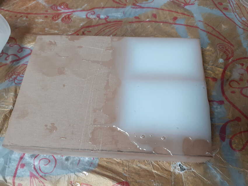
Leave epoxy for 14 hr at least
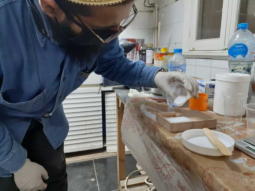
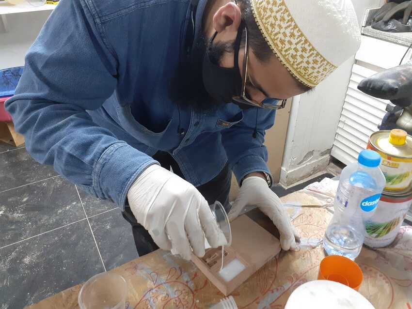
While pouring from height, small amounts slowly , and steady.
for workflow information click here .
Safety:

    1. Gloves to protect the hands
    2. The work area must be well ventilated.
    3. Protective gloves and safety glasses must be used
    4. If anything got spilled on hands, it must be washed very well
    5. If it reached the eyes, it must be immediately washed, and a doctor must be consulted
    6. It's a bad idea to smoke or eat while handling these materials
    7. The package should be stored in a temperature less than 35°C
    8. Plastic sheet on the working surface to protect the surface.

image image

Weekly assignments

Group Assignment

Here is the link to the group assignment page.
In this week’s group assignment, we practically did hands-on experience using modela player toolchain and we completed surfacing, roughing and finishing a small one part molding a semi-circle. Also we learned about silicon, polyester and epoxy materials and the concept of mixing A with B in a specific ratio. Moreover, both our instructors emphasized on safety measures along the whole day.

image image
image

We started with preparing our file in modela player 4.0 in the lab, we kept Mr. Ahmed’s documentation as a helping reference while preparing our file.I learned this tool chain for the first time. Especially, how to add a new tool in this application and setting cutting parameters where we can choose the materials for the tool to cut with specific speed rate.
We used 1 / 8 ‘ bull nose for surfacing and roughing , as for the finishing 3/32’ bull nose.

image
image

We started machining on a mdx-20 router machine, it took about 4 mins surfacing and 20 mins roughing. There was also a technical connection fault while finishing, so I learned how to cancel a job which was very important as well.

image
image

While machining we started going through the different materials silicone, polyester and epoxy. Prof Neil mentioned in the class about putting rice or water to know the quantity needed for any specific project. I learned that day about the actual concept around it that the mathematical equation is density (g/m3)= mass(g)/volume(m3) . For the mixing ratio it's not about mass but it's related to the volume A:B ratio. So for example, if we add the water on the molding wax and measure it on weighing scale i,e 15 gm and the density is known just can be searched from google which is 997 KG/m3 so now we can easily use online calculator to calculate the volume = mass/density = 15 cm3. And this is how we calculate the ratio between A:B .
For the silicone the ratio was 10:1 in volume so from google the range of silicone density is from 0.95 to 1.20 g/cm3 (if we take the average 1.05 g/cm3) and we tested on small amount of mass around 5 gm so the volume was the result was 4.8 cm3 . we can easily calculate the B volume just by dividing by 10= 0.48cm3 and re calculate the formula to get the mass = density * volume = 0.5 g which we weighed and mixed it, it turned out perfectly.
My role was scattered throughout the day, nothing specific as I adjusted the Z axis on the machine when I changed the tool to 3/32’ bull nose end mill bit. Also, mixed the silicon as specified above A:B and stirred it.
It was a very nice experience and I loved to explore new things and was looking forward to actually doing my assignment

image

Weekly assignments

Individual Assignment

This week I had to design a mold around the stock and tooling that I will be using which is chemical wood and bullnose 1 / 8' end mill bit then mill it (rough cut + (at least) three-axis finish cut ) on mdx-20. Last but not the least, use it to cast parts.
For the CAM software, I installed modella player which was recommended as a CAM software for machining on mdx-20. And I also installed its plugin virtual modela to calculate the timings even if I'm far from the machine but has an error which I have mentioned in the challenges section.

image
image

As for the design, I chose to make a mold of Ramadan lantern called fanoos as the holy month of Ramadan was starting soon. To do that I first sketched the model on a paper to get some idea of my model and also included a ring which acted as a keychain holder.
Then I started drawing a simple sketch, since I had divided my fanoos lantern into 3 parts top, base and bottom. I drew a line and marked it accordingly. Then I constructed new offset planes on those heights so that I can draw a 6 sided polygon with different diameters. Last but not the least I used the Loft tool to create a solid part between every 2 planes in the shape of the polygon so that in these few steps I had drawn a 3d fanoos with the style I wanted.

image
image

Then I used a “revolve tool” to create the upper cylinder part which connects the ring to the lantern. After adding filets to all sharp corners I finally split the body into 2 halves so that each will represent the positive part.
According to the stock material I had to adjust the measurement of my model so that is why I used the scale tool to uniform scale my model according to my needs. I had drawn my model initially according to 90x70x20 hoping to fit in my 6hr slot. As mentioned in the challenges section I had to scale down 0.5 in the fusion 360 to meet my wrongly slot timings.
I also designed the block to have a complete mold with the register keys and tabs in it. So, I used the combined tool to combine my model with the block. As for the openings for the block I had used a shell tool 5mm thickness so that I have a grace amount to add the negative register holes.

image
image

For the register keys, I created a new sketch on the surface of the block so that I can easily extrude join/cut in the both blocks by this single sketch. Initially I had drawn many things but due to the error which I have mentioned in the challenges section, I was finally satisfied with 6 circles as registers. So I used the mirror tool to mirror 3 of them. The diameter of the circles were 8mm for 4 circles and 5mm for the remaining 2 circles.
I finally exported both block parts as STL binary and saved it into a flash drive to open it in the Lab’s computer.

image
image

Here is the final model, To view the other half hide the active final part from the properties icon.

image

Machining.
First of all, I had to check/prepare the CAM software after I downloaded it. I selected mdx-20 in the machine settings from the file menu. Then added the appropriate tool for both roughing (1 / 8” bullnose 2 flutes end mill SE , AL TIN coated) and finishing (3/32” bullnose 2 flutes end mill SE , AL TIN coated), from options tab - Add / Remove Tool

image
image

Then I opened my STL file by navigating to file - open. And from the top right toolbar, I selected the material chemical wood. And in the model button I readjusted the orientation so that the top of my block is upright in the z axis.
Then again from the same toolbar, modeling form button I checked my dimensions especially the cut depth which is 15mm.

image
image

After all was set I finally clicked on the new process button and followed the wizard to complete my new process selection. Type of the process is the first selection in the window, either roughing or finishing or surfacing. Then in the cutting surface I kept the default settings and clicked next.
Time to choose the tool for the process, as mentioned before roughing (1 / 8” bullnose 2 flutes end mill SE , AL TIN coated) and finishing (3/32” bullnose 2 flutes end mill SE , AL TIN coated) which will be shown in thw drop down menu.
Tip: If not shown, recheck the Add tool options and recheck the material is registered in this tool options.

image
image

The next option cutting area and depth kept it as default, then moved to the type of tool path to create - I selected X axis. And checked that the cutting start point is from the lower left.
Lastly, setting the cutting parameter, Thanks to my friend and colleague ENG Omar Seif who suggested maximum speed value by calculating the chip load. He quoted that if we are using 1 / 8” endmill , 1m/min = 16.6mm/s is good if we consider it(chemical wood) hard wood. We can even go faster but let’s stay with minimum load. So that is why I used these settings:

    1. XY speed = 15
    2. Z speed = 3.5
    3. Spindle = 6500.
    4. In roughing cutting in amount and path interval = 1.5 and final margin =0.1.

In finishing nothing is needed.
Then to check the time I chose to cut later. Finally clicked on the finished button.

image
image

From the same toolbar down at the bottom, I generated the tool path by clicking on the create tool path button and then clicked on the preview icon to view / simulate and know the estimated time which the machine will take to complete fabricating it.

image
image

After that it was time to cut. The machine started cutting as my heart started pumping to not do anything wrong.
After each process I changed the tool for the other process to commence.

image image
image

I had already prepared the chemical wood from the start as we prepared for the pcb stock, by sticking double faced tape. Here is the output.

image image
image

After finishing machining I discovered the design faults in the mold, the space between the wall and the register keys were not enough to pass through the roughing and finishing process. So It made a joint between the register keys circles with the wall. In the challenges section, I have mentioned the solution for it. So this was the only post processing needed after machining.

image
image image

Now for the fun part, pouring silicon on this mold. I used locally purchased silicon with its hardener which was already in the inventory. As discussed in the group assignment I calculated and found this ratio 30:1 worked very beautifully and I was able to pour on the mold, after some tapping to avoid any kind of bubbles. Since This was my first time I still got some bubbles but thankfully on the top not on the bottom. I left it for more than 14 hrs (recommended by previous fab academy students in their documentation).

image
image

After 14 hrs I removed it from the chemical wood mold, it felt very fragile so I carefully removed it, also had to pull it by force at the same time.

image
image

Post processing silicon: due to neglicance in design orientation the opening holes didnt match both orientation together, so I had to cut some pieces and make it a big hole to pour polyester in it.
Casting polyester: Then I poured polyester which is also purchased here locally and the ratio was 1:10 according to the test conducted in the group assignmnet above.
I also added yello dye color to give the polyester yellow color so that the it will give my lantern bright light color.

image
image

Here are some hero shots

image

Voila its done

To sum up, I completed the following:

    • √ Linked to the group assignment page and reflected on your individual page what you have learned.
    • √ Reviewed the safety data sheets for each of your molding and casting materials, then made and compared test casts with each of them.
    • √ Documented how you designed your 3D mold and created your rough and finish toolpaths for machining, including machine settings.
    • √ Shown how you made your mold and cast the parts.
    • √ Described problems and how you fixed them.
    • √ Included your design files and ‘hero shot’ of the mold and the final object.

File: Download fusion360 + STL files.

image image

#Challenges 1

Virtual modela time wrong: The extension virtual modela for previewing the generated tool path and estimate working time. I was dependent on my laptop's extension which was indicating that one block would take 9 hours and after rescaling and removing still 6 hours. But when I opened the same file in the lab it turned out to be only 2 hours.

#Solution 1

Be dependant on the final computer’s system, because of this I had scaled my model by 50% and the block size from 90x70x20mm to 60x40x15mm, also I removed useful register key tabs and reduced the ring size on the top. Not to mention, reduced the pour and air vent sizes for aesthetic view.

#Challenges 2

After machining I observed that the register key circles were connected to the wall, and there were some cuts on the top of the wall which indicates that the shank of the bit had collided with the wall.

#Solution 2

I used the manual milling tool called hand craft with the smallest bit I cut the gap between the circles and the wall, but still was not perfect which led to some leakage problems (#challenge 3)

image
image

#Challenges 3

Silicon mold had defects.

#Solution 3

The opening in the bottom was patched by extra silicon part and a small piece of wood to extra leakage prevention measures. As for the misalignment of the pour / air vent openings, by using the cutter I made a big whole so that instead of 2 openings it would be just one.

#Challenges 4

While casting polyester in the silicon mold, It started to leak.

#Solution 4

After some time I realized that the tapping process after pouring made the bottom wood part to get loose so that the polyester got the chance to leak because of the gravity. So I applied pressure to make the wood join to the silicon again. And it worked.

image

Aknowledgment

    • √ Special Thanks to my friend and colleague Omar Seif who always kept his patience while sharing his experties and making me understand the core concepts very easily.
    • √ Thanks to Mahmoud Abo ElNaga I have learned alot from his documentations for this week. Also ENG Noha, Helped me alot this week, specially by supporting day and night with her guidance and feedback.