Week 7 Computer Controlled Machining

Assignments:

Group assignment:

    • Test runout, alignment, speeds, feeds, and toolpaths for your machine.
    • Document your work (in a group or individually)

Individual assignment:

    • Make (design+mill+assemble) something big.
    • extra credit: don't use fasteners or glue.
    • extra credit: include curved surfaces.
    • Post processing → sanding, painting.

Learning outcomes:

    • Demonstrate 2D design development for CNC production.
    • Describe workflows for CNC production.

Weekly practice

Research

    • Workflow.

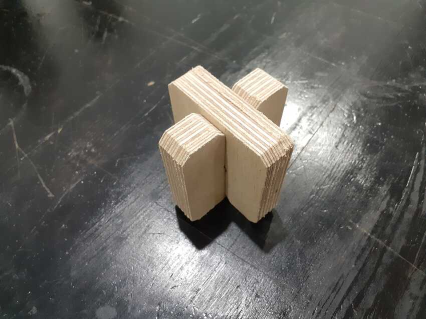
1) You should have an idea of what you want to make and it is recommended to make a solid draft using pencil and paper.
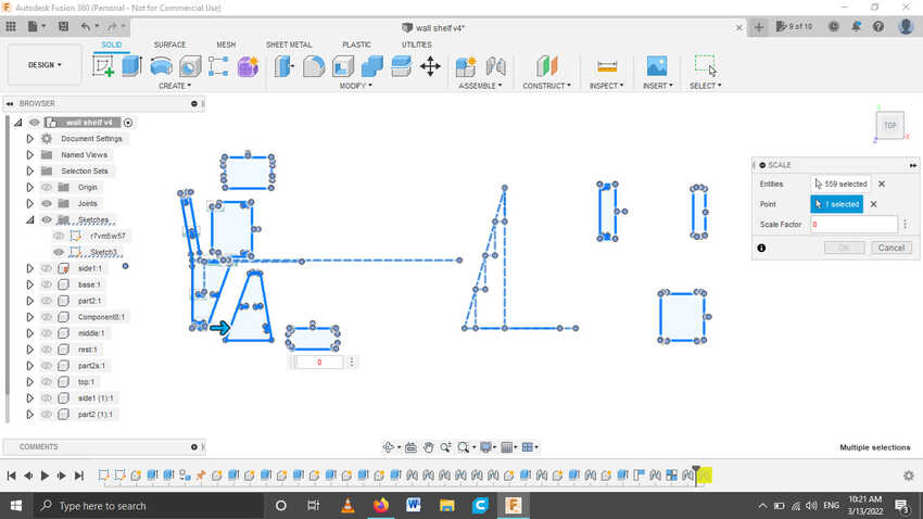
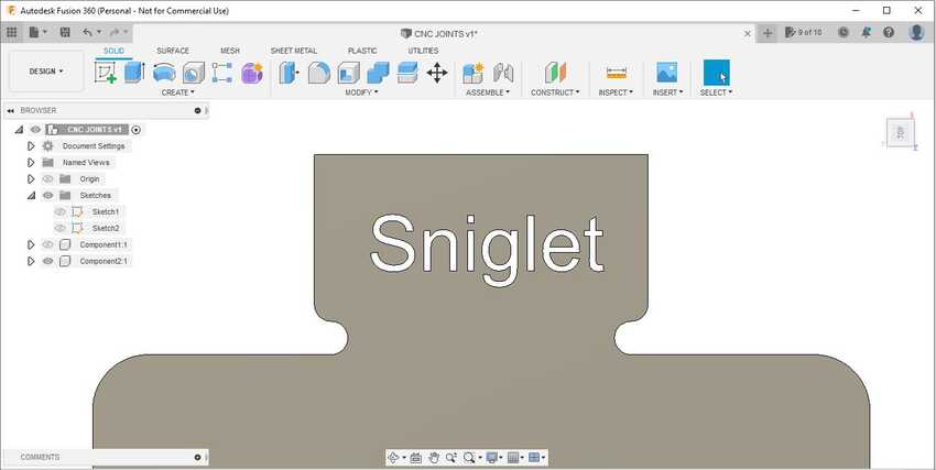
2) Either 2D or 3D dessign, you have to design on a cad software like Fusion 360, FreeCAD, SolidWorks, ...etc. and have the digital file in a supported format.
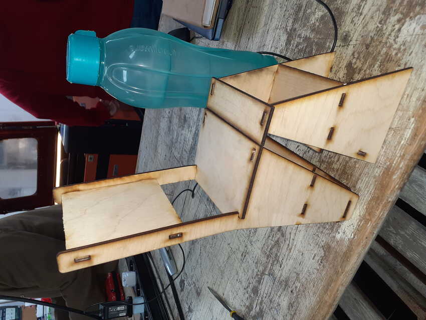
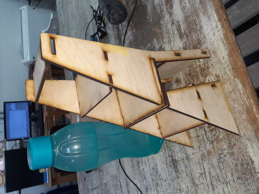
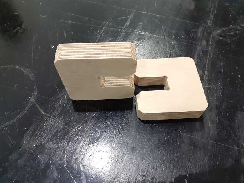
3) The most important Choose the suitable material for the design and the machining type.
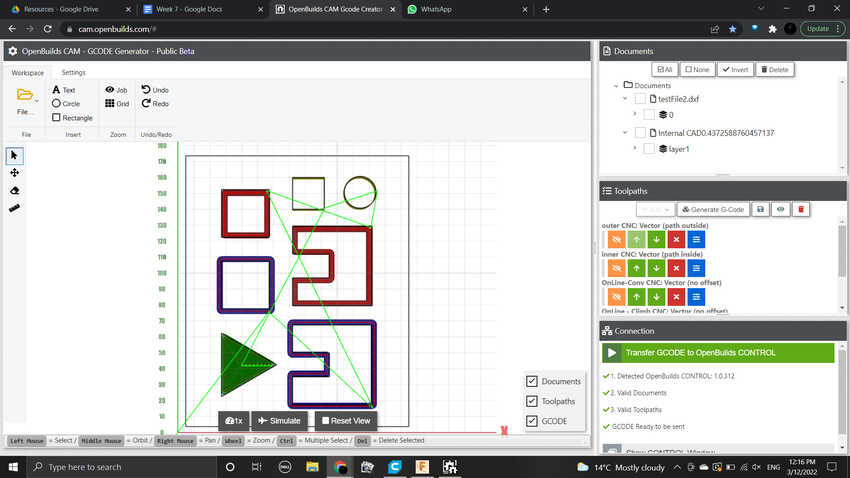
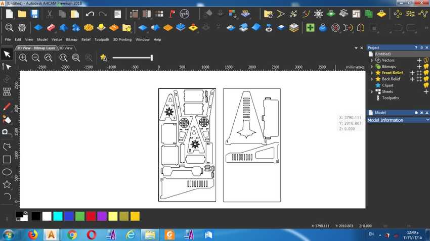
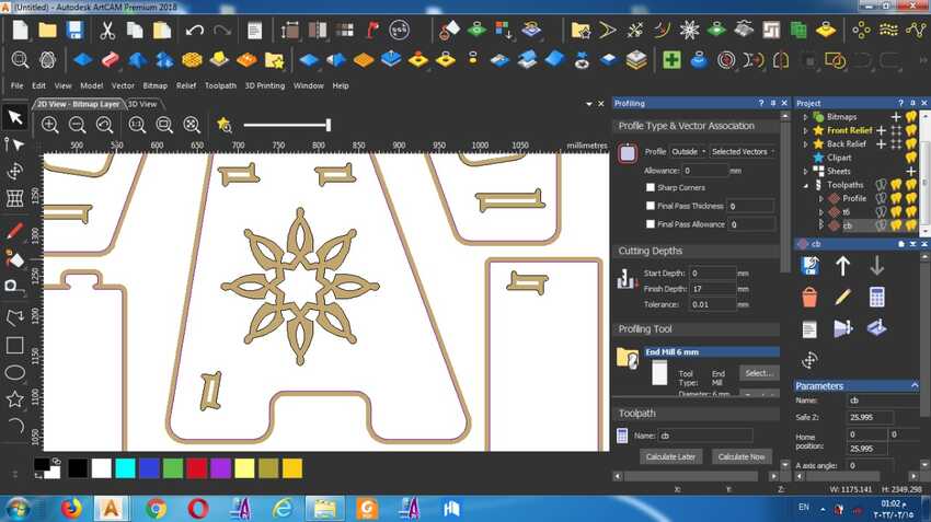
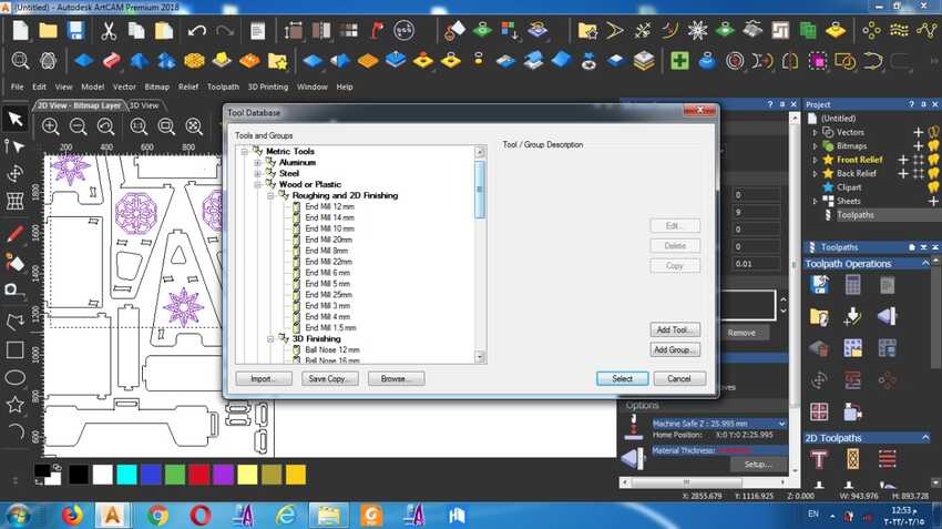
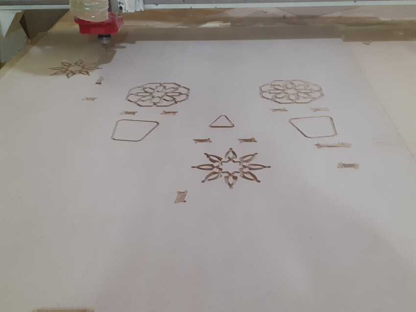
4) As for the CAM software also known as toolpath, here you select the appropriate cutting tool and set its cutting parameters, select the toolpath type either 2d or 3d, select the toolpath operation, setup the material and its orientation, simulate the program and export the supported code for the machine.
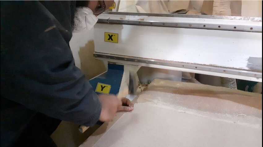
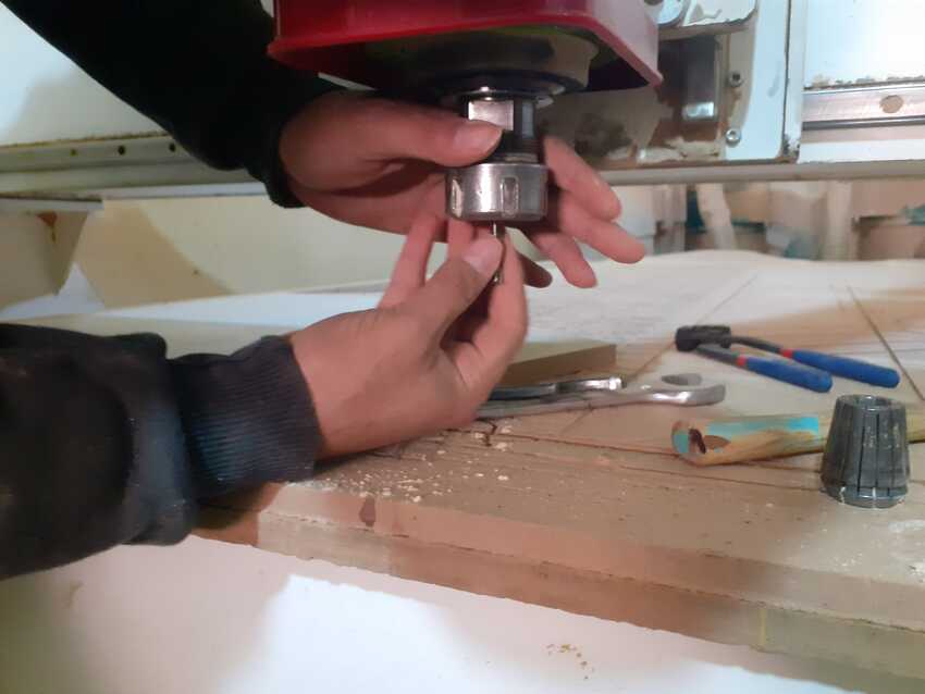
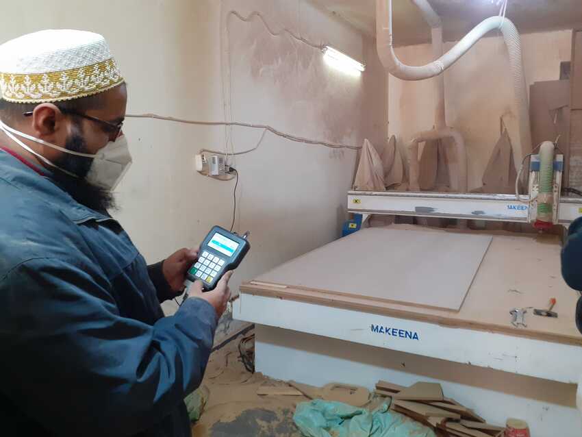
5) The easy part, Load the codes into the operating software, fasten the material on the machine bed, fix the tool in the spindle, set the origin points for the axes, dry run then actual run.
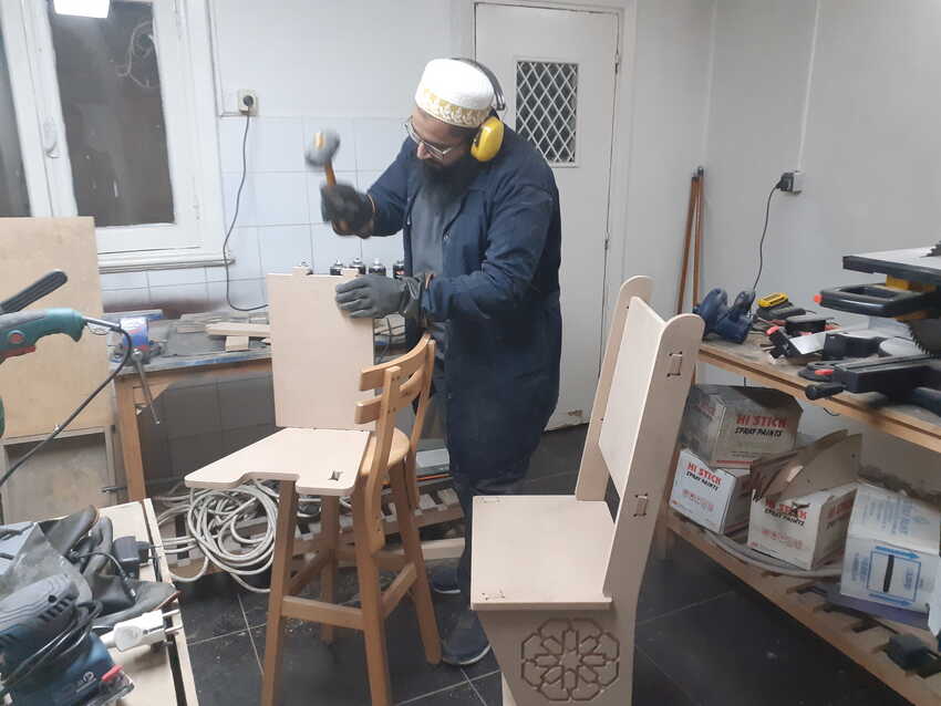
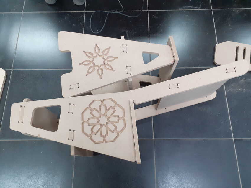
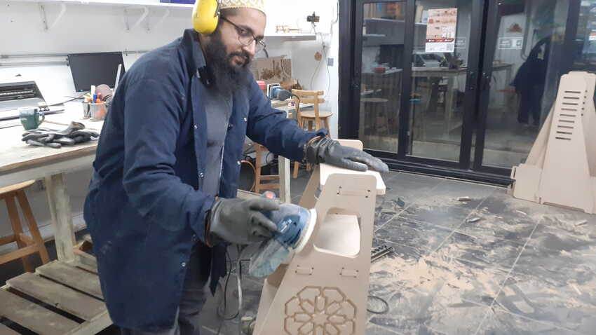
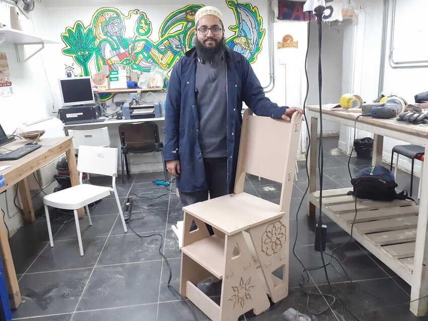
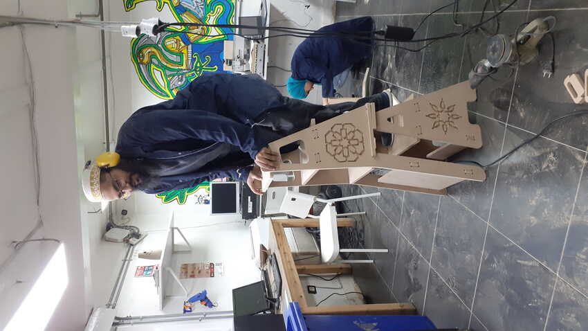
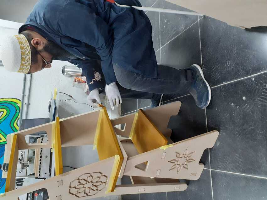
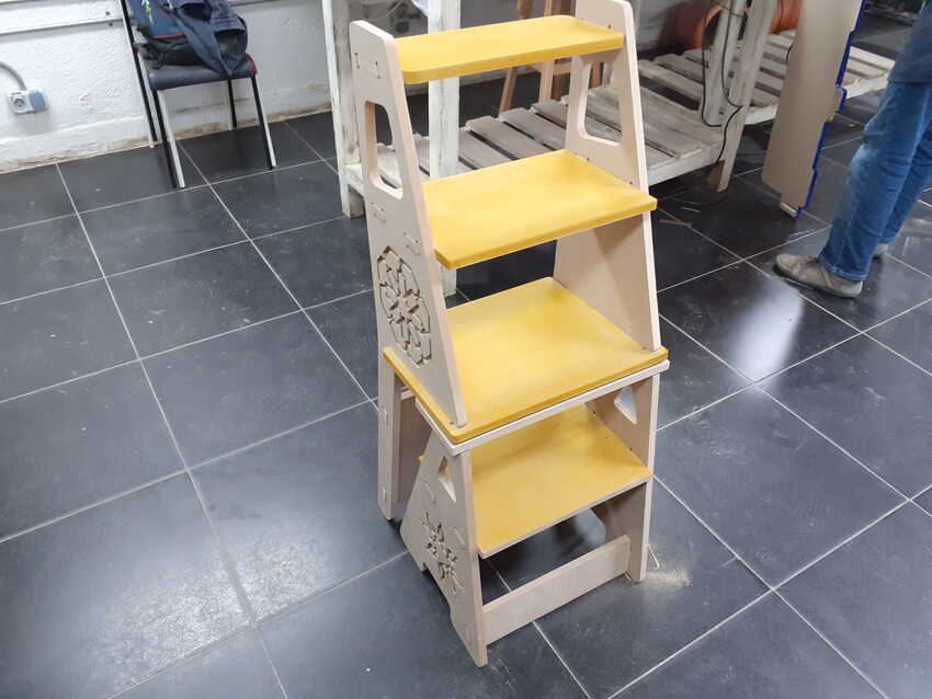
6) Post processing like sanding, painting, or any required post processing operations.

Need to know this week, this documentation really helped to understand the basics.

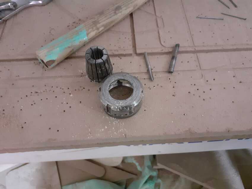
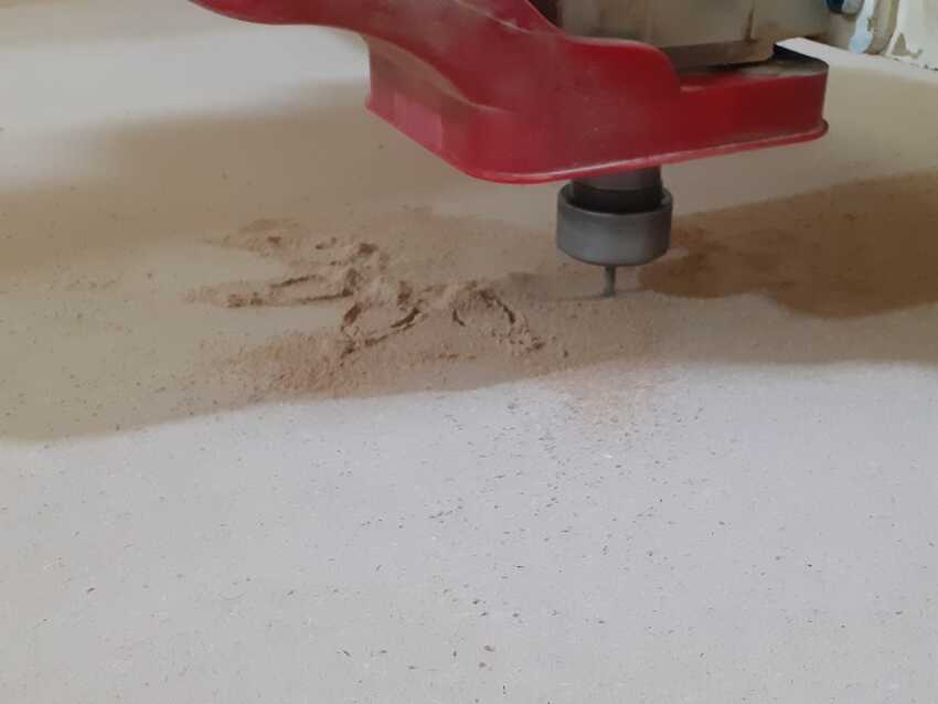
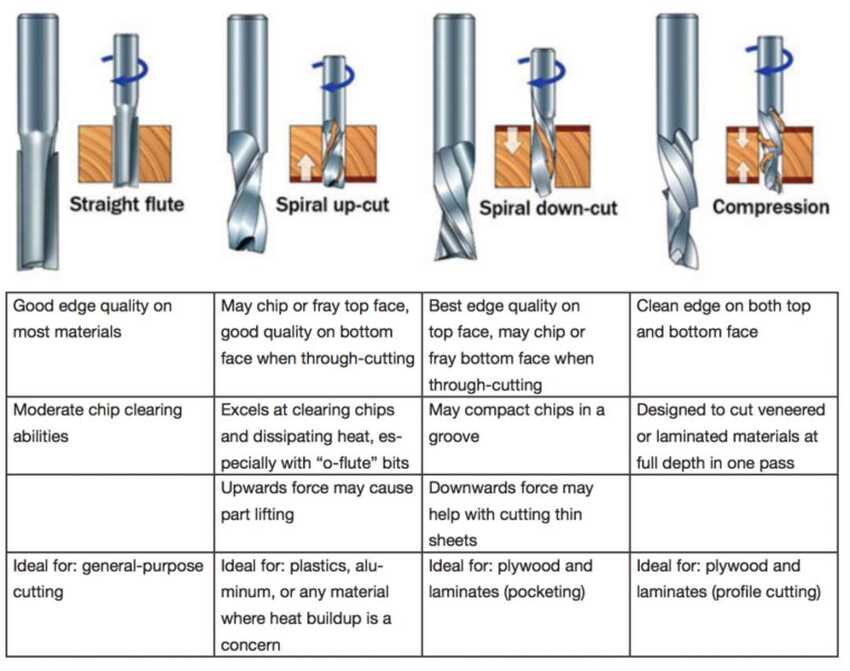
    • Bits, Feeds, Speeds.

The challenge of getting a good CNC cut is in selecting the best tool for the job (Bit), the optimal cutting speed (feed rate) and router/spindle RPM (speed of rotation) for your material.

    • Flutes.

The end tool or Bit closely resembles a drill: it consists of a round shaft with several blades (flutes) wrapped around it in a spiral fashion. The difference is these flutes have a sharp, exposed edge running along their entire length. This is because the bulk of their work is meant to be done by moving sideways,
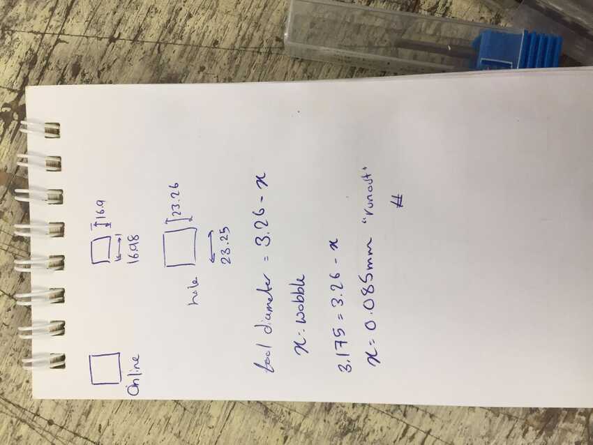
    • Chipload.

Chip load is the size of the chips produced during cutting. This is dependent on the Bit you are using and the cutting speed. The goal is to get the maximum chip load possible to increase productivity, reduce heat, and prevent the tool dulling.
When the chip are too small (or you are producing sawdust) the Bit can overheat and dull quicker. When chip load is too high, the tool can deflect creating a bad surface finish and, in extreme cases, even break the Bit. I used the Fablab Speed and Feeds Calculator to determine the chip load for plywood.

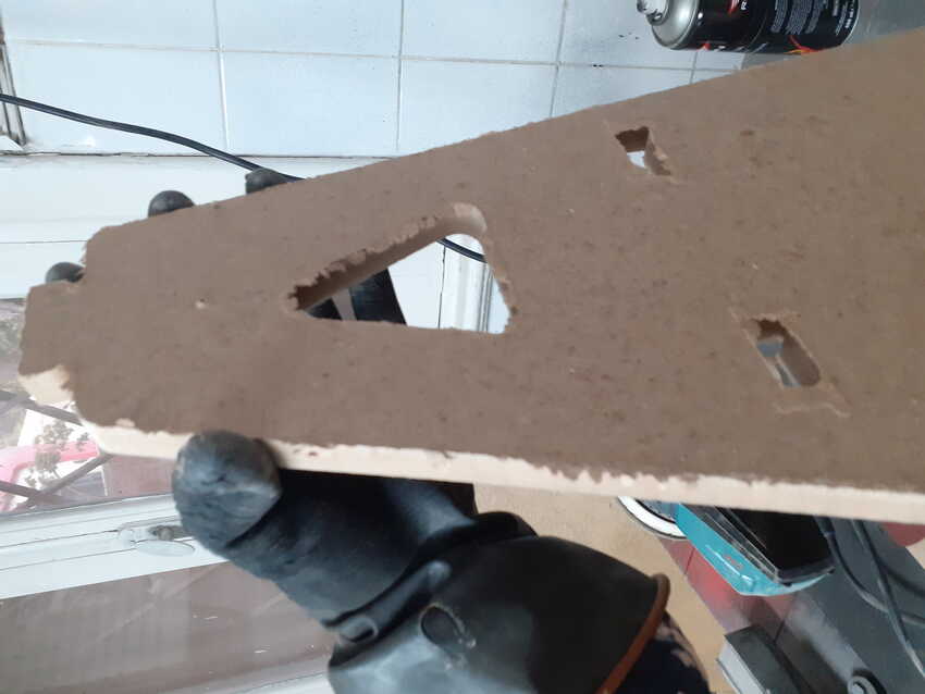
    • Safety Tips with the CNC Router.

1) Never leave the room while the machine is routing.
2) Do not put any part of your body closer than 6 inches to the cutting tool when it is moving.
3) Always use eye and hearing protection When the machine is working.
4) If the bit is acting up or breaks, shut down the machine straight away.
5) Do not force material into the router.
6) Make sure that all workpieces are securely clamped down.
7) Always make sure you have inserted the correct bit for the job you are doing.
8) Do not operate a CNC router in a damp or moist environment.
9) Clean the machine and the floor around it after every use.

image
image

CNC Joints designing

I Followed this video to gain knowledge about different types of CNC design joinery, specifically corner compensation. I found that singlet is very effective and the recommended one that is why I decided to use it in my assignment.

image image
image

Toolpath

I designed a Box with finger press fit (dovetail joints) and sliding on the top and bottom. Then I explored the fusion 360 manufacturing workspace as a tool path for a CNC machine by following this video .
I also simulated my design to view the pockets and the cut through difference.

image
image

Weekly assignments

Group Assignment

Here is the link to the group assignment page.
This week we had to test runout, alignment, speeds, feeds, and toolpaths for our machine. So as they say, start small :) we first characterized the china router (30*40 cm) CNC machine then before the assignment we tested again on the big machine. The design was made by our instructors. It was a simple design consisting of squares and circles to test on.
Open builds CAM online software was used as the toolpath to generate the .gcode file.
And we started the machining process as shown in the video below.
After that we just had to measure the dimensions of all parts milled, and we found that the runout is about 0.085mm. and that was a satisfying output.
Cutting Parameters:

    • Endmill diameter = 3mm
    • Z safe height = 5mm
    • Cut depth per path = 1.5mm
    • Feedrate = 200mm/min
    • Feedrate (Plunge) = 300mm/min

Runout calculations:
According to my understanding the runout is calculated as follow: x= actual lenght - online 2d drawing lenght - tool diameter, so as shown in the picture below we had drawn 20x20 mm cube and milled on line, the tool diameter = 3.175.
runout = 23.26 - 20 - 3.175
runout = 0.085
The alligment was also very good as the pocket depth was exact, as enterd in the CAM software which was 5mm.

image
image

Then we moved on to explore other toolpath CAM softwares. My role was to generate a .gcode file by using the Fusion 360 toolpath. Due to time constraints I couldn’t debug the error which displayed but I am looking forward to getting back to it after finishing my assignment.

image

Individual Assignment

For this week’s assignment I had to think big to fabricate something big. So I thought of something useful that would be used anywhere. A chair cum ladder it's very useful and doesn’t need 2 separate entities instead a combined one which will save the space and the effort also.
My inspiration for this week’s design was this model and I pretty much loved the design as an architectural aspect more than the concept :) so I decided to make one from scratch and had a help/reference from another model for the measurements to help me think big.

image
image

So it all starts as an idea/concept in my brain transferred roughly on a sketch on paper as shown above. Then I started designing a small prototype model to laser cut it first. Scale tool was then used to enlarge the whole sketches - I enlarged it 4 times so that every measurement turns 4 times larger than the small prototype model. The most important part, I added corner compensation sniglets on every corner . The full design was parametric in consideration of clearance/ runout ( for a perfect press fit joint), stock thickness (for the dimensions of the finger male and female joints) and tool diameter ( for the measurement of the sniglet’s diameter). Lastly I exported it to a DXF file to easily open it on any CAM software.
Here is my model.

image
image

This is the prototype model for my model, the aim for this step is to visualize and confirm the concept before diving into the big machine and correcting any mistakes before it.
The observation was to recalculate the height and the length of the steps for a proper and comfortable angle to climb on. Also expected to fail is the success in gaining peace. My instructors and mentors advised me to be ready for any adaptation in this model, for example if the wood quality is weak it may break while climbing the steps so I should be ready to think out of the box and adapt accordingly - turn the ladder into a shelf for light showpieces for a better use. For these kinds of feedback and many more I deeply thank them and pray to learn from them in every way possible.

image
image

For the assignment I explored a new tool path Auto desk ARTCAM , which is famous in this region so that way I was able to explore it with professionals who work on it in day to day life.
First step was to import the DXF file into the ARTCAM software and start nesting it. Resource management is mainly done in this part to avoid dissipation of the wood sheet. Since I was going to cut with my dear friend/ colleague Omar we both merged our files and did nesting together for our requisite wood sheet (122x244x1.7cm) MDF, it took 1 sheet and a half.
Second step was to choose and identify the type of operation for every profile line. For my assignment I had used 3 operations: 1) For the 2 Islamic designs I used the pocket operation - to cut a certain amount of wood and keep the remaining intact. A 9mm pocket was used for my 2 designs.
2) Inside cut operation for all the cut through operations which were inside the profile, it maintains the dimension of the opening for the outside.
3) Outside cut operation for all of the profiles of my design which cuts outside the profile line and maintains the profile dimensions.
Third step changed the profiling tool settings: tool : End Mill 6mm
Step Down 6mm
Feed rate 150 mm/sec
Speed 15000 rpm
Fourth step: generate gcode for the machine and start machining.

image image
image

Before fabricating, I prepared the CNC machine by changing the tool to 6mm end mill bit 2 flutes. And screwed my sheet on the sacrificial bed for a rigid fixture.

image image
image

Also as mentioned before we tested the clearance on the big CNC machine and checked the parameters of my design to avoid any miscalculations.
Observation add clearance/ run out of 0.3mm to have a perfect press fit joint.

image
image

Now for the fun part, big CNC machining!!! At first the control interface was new for me that is why I had to keep asking before pressing anything :) then as I got the heck out of it, I was using it like a video game controller :)

image
image

At last the machine started cutting while I started praying for good results.

image
image

The observation is mentioned in the challenges and issues as I faced them in the assembling process. But all in all, after lots of hammering, I finally completed the process.

image
image

Since I was using MDF wood sheet the last layer didn’t cut neatly so I had to use 3 post processing processes. First by using wood filer ( to remove the excess layer), 180 sandpaper on a Bosch sanding machine and then finally for smoothing 800 sandpaper. Lastly, I used a blower to remove the dust from it completely.

image
image

Hero shots

image image
image

Extra step which I didn’t imagine doing was to color my chair/ladder so I was motivated by the team spirit to color it. I used the yellow wood dye color to paint the steps of the ladder only which gave a good look to my assignment.

image
image

Stay tuned for more additional work on my assignmnet.

image

Voila its done

To sum up, I completed the following:

    • √ Documented how you designed your object (something big).
    • √ Documented how you made your CAM-toolpath.
    • √ Documented how you made something BIG (setting up the machine, using fixings, testing joints, adjusting feeds and speeds, depth of cut etc.).
    • √ Described problems and how you fixed them.
    • √ Included your design files and ‘hero shot’ photos of final object.

File: Download fusion360 + dxf file.

#Challenges 1

During designing process I faced a major issue, that my laptop became so slow that after each click I had to wait for 2-5mins to compute it

#Solution 1

Upgrading is necessary now, working on it.

#Challenges 2

After completing the machining process, I observed that the clearance was a bit off so that the finger joints wouldn’t fit. And due to fillet in the bottom the chair began to rock a little bit.

#Solution 2

I had to use intensive sandpaper on the finger joints to remove some excess wood from both sides to hmmer fit the parts together, and use a hinge to overcome the rocking part.

image

Aknowledgment