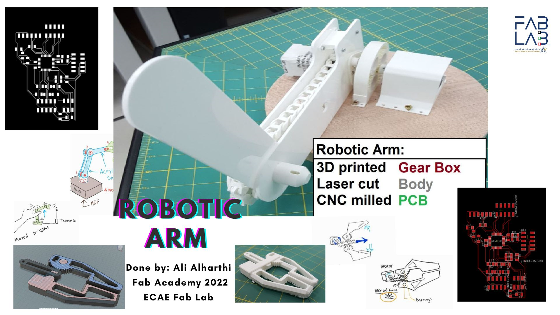
Final Project: Robotic arm
What will it do?
My main goal with this project is to learn about robotics by making a simple robotic arm, as I learn more I'm planing to increase the complexity of the design and add more feature but initially I want an arm with at least two limbs cabaple of moving seperatly.
Who has done what beforehand?
There are several examples of a robotic arm made in the previous Fab Academy classes, however since I'm going to use stepper motors the most similar project I found was the Kamplintfort lab 2019 machine design week,
also similar was the machine design week of Vigyan Asharm node of 2018.
The design
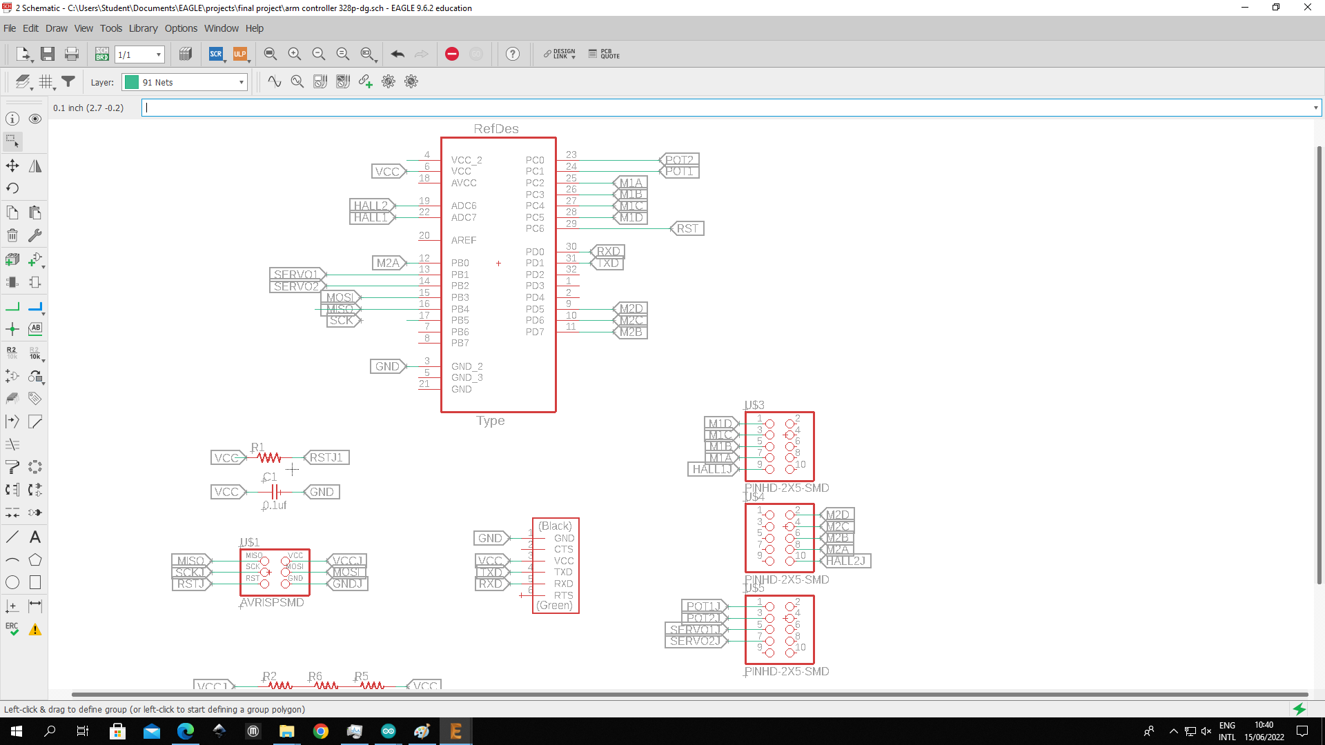
I made my design using Fusion 360 for the structural parts and used Eagle to design the PCB
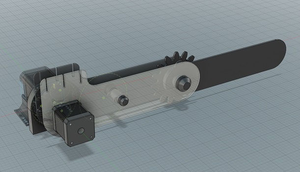
The Stepper motor mounts will be made of PLA and the limbs will be laser cut acrylic. I also planned to icorprate a grapper that I made in 3d printing week.
Bill of Materials:
| Quantity | Item | Link | Price | |
| 1 |
|
Link | 2.30$ | |
| 2 | Nema 17 stepper motor | Link | 16.00$ | |
| 1 | 1 Kg roll of PLA | Link | 23.00$ | |
| 1 | 3mm White Acrylic sheet | Link | 11.00$ | |
| 2 | A1342 hall sensor | Link | 7.00$ | |
| 2 | 10K Potentiometer | Link | 8.50$ | |
| 2 | 9g Servo | Link | 7.29$ | |
| 1 | Hookup wires | Link | 15.00$ |
All of the main materials I'll be using will be from the stock of the lab, the estimated total cost is around 75 USD.
Task completion status
I hit many obstacles that slowed down my progress and couldn't complete all of the design objectives, here is what I managed to implement and what I wanted to implement but couldn't.
Completed tasks:
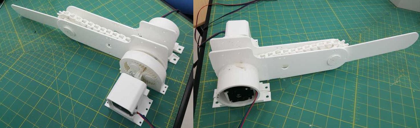
- Stepper motor mounts design and construction
- Arm limb design and construction
- Gearbox and chain transmission system
- Electronics design
Incomplete tasks:
- Closed loop motor system
- Integrating a grabber into the arm
- Making the PCB
- Finalize the code
Evaluating what worked and what didn't work
Stepper motors are not as suitable for a robotic arm as I though at the beginning, despite being precise they require specialized drivers my initial idea didn't include a gearbox since I thought the heavy stepper motors would have sufficient torque, to solve this issue I had to spend a lot of time learning about, and designing a gearbox and power transmission system which worked great for mitigating the low torque and heavy weight of the motors.
I also lost some time trying to figure out why the motors lost power after few seconds of operation, I used L298N motor drivers which are rated for up to 40V DC and 2 Amps, but using them with a voltage over 6 Volts caused them to overheat and disconnect, I only figured this out after testing out several power supplies which are within the published limits, my guess is that the drivers I have are knock offs with much worse specifications than the genuine parts.
I wanted to implement closed loop system using hall effect sensors and magnets but fitting the sensor along the center of the axles of movement proved tricky, I had to redesign the arm with bigger clearance to fit the sensors in place, as of now I haven't fit the sensors yet due to time constraints.
What's next
In order of importance, what still needs doing:
- Finish the PCB making.
- implement the grabbing mechanism.
- write controlling software..
- Incorporate closed loop sensors
What I learned from my project
This project taught me new skills and built on skills I already had, I got much better at using CAD software through using Fusion360, I developed knowledge of power transmission systems and gearboxes since I needed to learn it to make my project work even though it wasn't in the original plan, I learned how a closed loop system works and made plans to use it even though time was not sufficient, I achieved my goal of introducing my self to the field of robotics and I hope to use what I learned to further my studies and future projects.
Video of the assembly so far:

This work is licensed under a Creative Commons Attribution 4.0 International License.
You are free to :
Share — copy and redistribute the material in any medium or format.
Adapt— remix, transform, and build upon the material.