Input Devices
The second half of the Fab Academy programme is designed to build on the previous weeks. You will be synthesizing information and implementing skills that you were introduced to in the first half of the programme and encouraged to integrate these into your final project proposal.
***GROUP ASSIGNMENT***
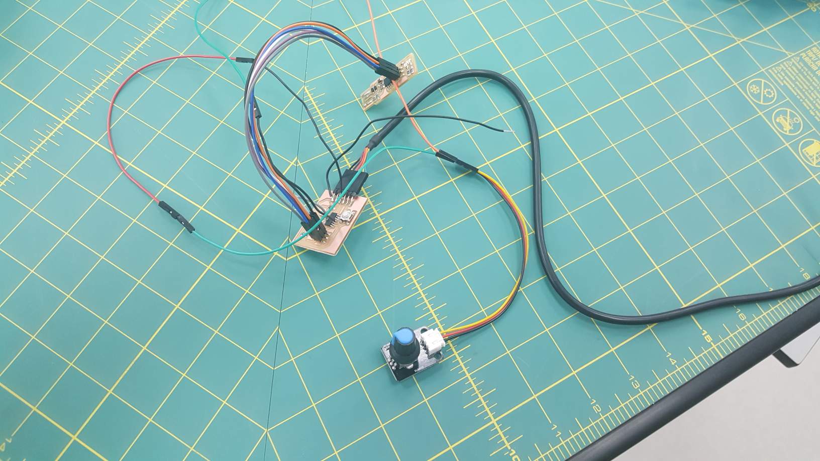
I continued to use my Attiny44 board that I made in the embedded programing week. The sensor I choose for this assignment is a 10K Ohm potentiometer in a self contained break-out board, it have 3 connections, VCC, GND and Wiper(V-out), Potentiometers could be used as position sensors and control devices which will be used in my final project.
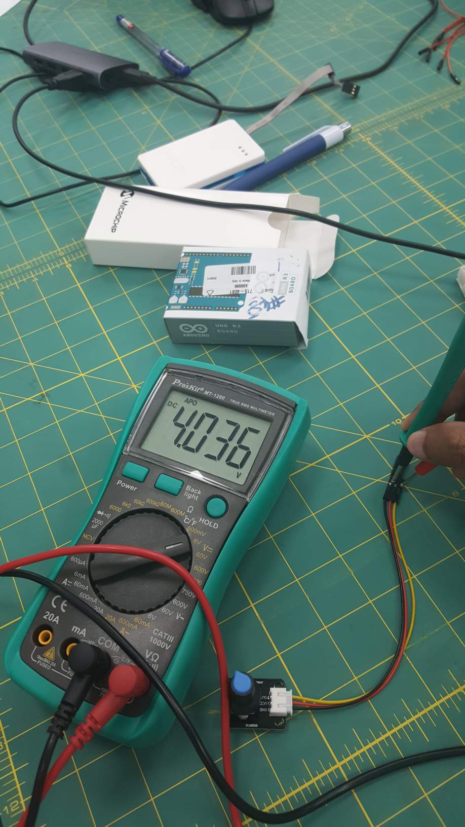
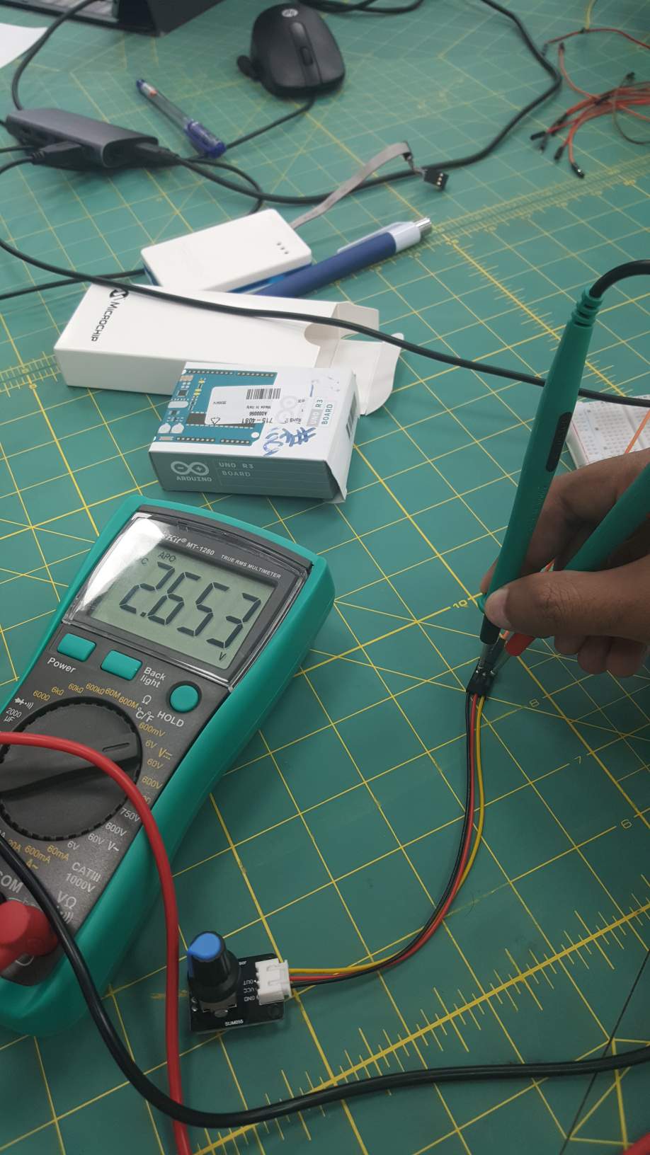
To test the potentiometer function I wired its VCC and GND to an Arduino Uno and used a multimeter to measure the voltage between the wiper and ground, at minimum angle of the potentiometer knob the voltage would read 0V and at maximum angle it would read 5V, this variable voltage can be read as an analog signal by one of the ADC(Analog to Digital) pins on the Attiny44, pin number 2(Arduino) is and unused ADC pin in my board so I decided to use it by soldering a jumper cable from it to the wiper(V-out) pin on the potentiometer.
I further soldered wires from the board's VCC and GND to the potentiometer VCC and GND instead of continuing to use the Uno board,.
I wrote the following code in the Arduino IDE using the "Attinycore core" board which adds several useful libraries and features to the Attiny's Arduino implementation, the most important one is Serial connection on pins 0 and 1. to install the core follow the guide here.
const int Pin = A2;
float  raw ;
void setup() {
  // put your setup code here, to run once:
  Serial.begin(9600);
}
void loop() {
  raw = analogRead(Pin);
  Serial.print("Raw value: ");
  Serial.println(raw);

  float voltage = (raw / 1024.0) * 5.0;

  // Send the voltage level out the Serial port
  Serial.print(", Volts: ");
  Serial.println(voltage);

  float pos = (100*voltage)/5;

  Serial.print("Calibrated value: ");
  Serial.println(pos);
  delay(500);
}
The Attiny's ADC is 10bit, meaning that when reading the maximum voltage it will output an integer with the value 2^10, in other words at 5 volts the pin would read a raw value of 1024, to find the actual voltage divide the raw value by 1024 and multiply it by 5V, I added a 'pos' variable to show the knob's position from 0 to 100 which will be outputted in the serial output as "Calibrated value"
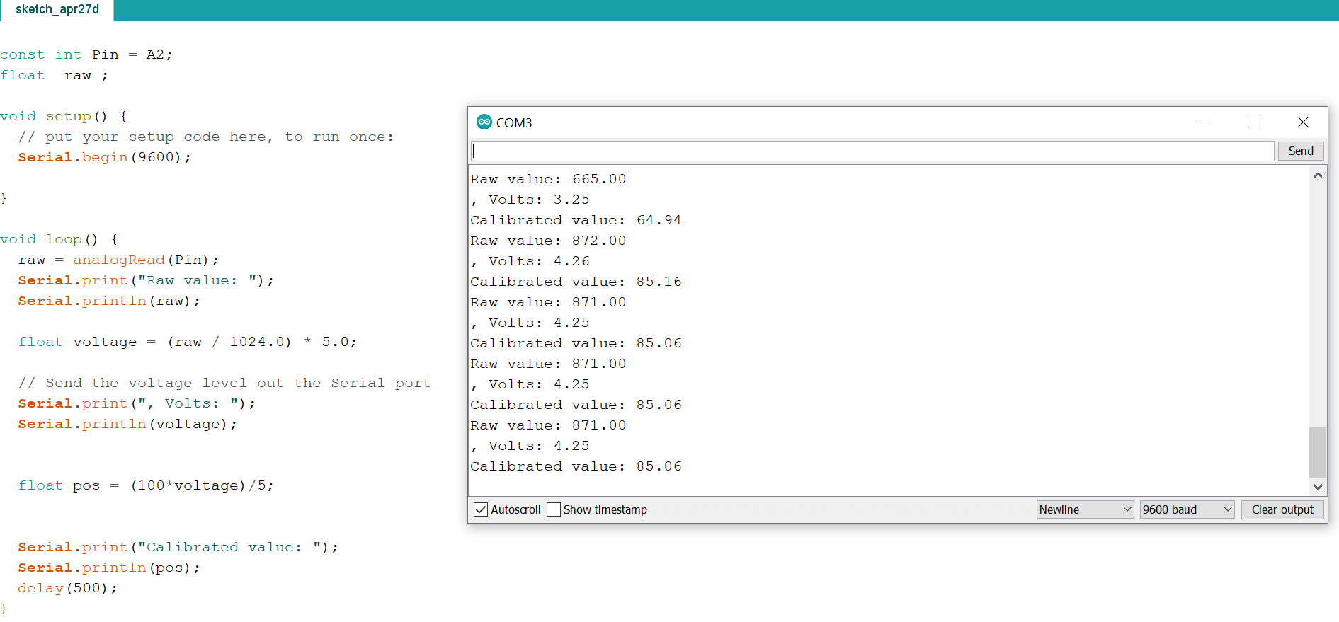
Here I twist the knob and notice how the values in the serial monitor change with my inputs.