Group Assignment – Computer controlled cutting - Querétaro
General objective (group assignment):
- Characterize the design rules for your PCB production process.
Roland Mill SRM-20
Technical specifications:
- Work Area: 8" x 6" x 2.38"
- Loadable Workpiece Size: 8" x 6" x 2.8"
- Table Size: 9.14" x 6.17"
- Max Tool Size: 1/4" or 6mm.
- Spindle Speed: 3000-7000 rpm.
- Operating Speed: 1.18 in/sec or 30mm/sec.
- Mechanical Resolution: 0.00008in or 0.002mm.
- Acoustic Noise Level: 45-65dB (A)
Development
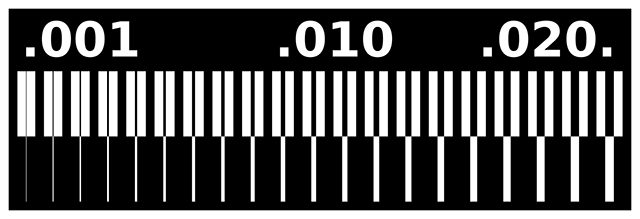
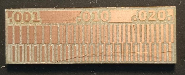
For this assignment, we engraved a 100mm x 100mm PCB blank board using the tolerance test board.
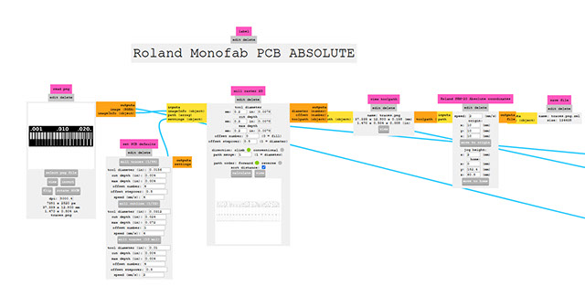
First, we imported the image to the FabModules inteface to set the minimum requiremnts in order to print and engrave.
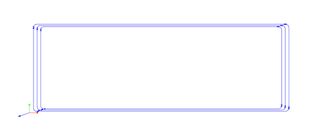
Next, once the image is imported, we select the type of machine we would like to use, the dimensions of our tool, the offset number (how many equidistant perimeters are going to be engraved to remove copper around the graphics, 0 means Fill, so the machine will remove ALL material outside the graphics) and the stepover (the distance between perimeters, which is reflected in the final resolution).
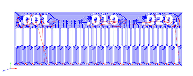
These settings will generate a motion path like this:
After clicking the Save file button, we created the .rml file.
And we made another file to cut the board:

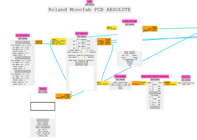
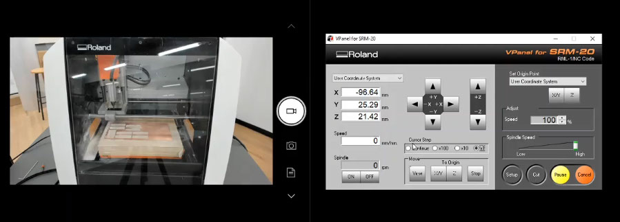
Then we send the files downloaded from Fabmodules to the drilling machine using Vpanel.
And this is the result:
Results
Parameters optimized for the machine.
Roland SRM-20
PCB milling
Traces (engraving)
Tool diameter: 0.20 mm
Cut depth: 0.1 mm
Max depth: 0.1 mm
Offset number: 4
Offset stepover: 0.5 mm
Speed: 4 mm/s
Perimeter (cutting)
Tool diameter: 1 mm
Cut depth: 0.5 mm
Max depth: 1.5 mm
Offset number: 1
Offset stepover: 0.5
Speed: 4 mm/s