Group Assignment – Computer controlled cutting - CDMX
General objective (group assignment):
- Characterize the design rules for your in-house PCB production process: document feeds, speeds, plunge rate, depth of cut (traces and outline) and tooling.
- document your work (in a group or individually)
- Document your work to the group work page and reflect on your individual page what you learned
Roland Modela MDX 20
Technical specifications:
-
Size:
- Table: 220 mm x 160 mm
- Operation Area: 203 mm x 152
-
Modeling Functions:
- Maximum resolution: 0.00625 mm/step
- Speed: 0.1 to 15 mm/sec
Development
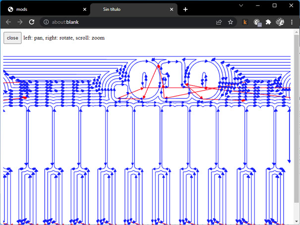
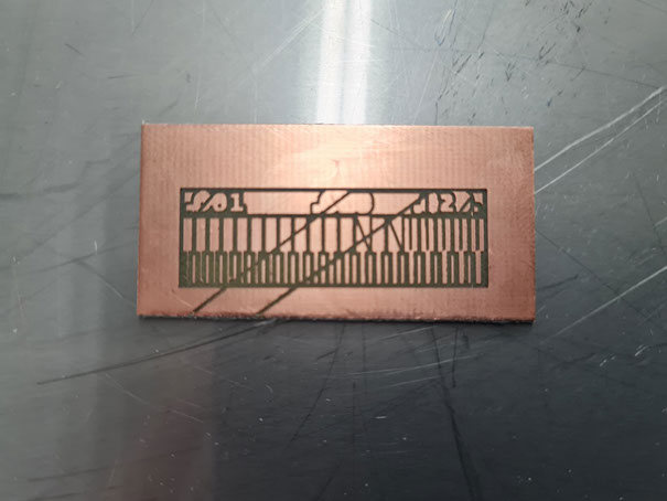
To characterize the design rules, we used an image that we got from the fabacademy webpage. It will be used to set the parameters that should be used while milling our boards. The image can be found at: https://academy.cba.mit.edu/classes/electronics_production/linetest.png
https://academy.cba.mit.edu/classes/electronics_production/linetest.png
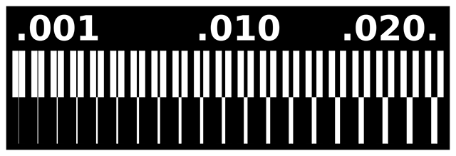
The image has different line sizes that, when using the machine to mill a circuit board, represent the size of traces within our boards, and we will need to make several tests to find the correct parameters in order to get lines as thin as 0.001 in. wide.
To get the machine to mill the image above you have to follow the next steps:
1. Get a design: When you get or design your own circuit board, you should export it (or download it) as a png file. To make this assignment you only have one image, but if you are milling a board, you should have 2 or 3 images:
-
- Traces
- Outline
- Holes.
2. Mods: You have to translate your design into a language the milling machine can understand, we will be using .rtl files (Raster Transfer Language). As we now have a png image, we must use Mods. Mods, is a sequence of processes that will convert from our design into the sequence needed by the milling machine to operate. You can find mods at: http://mods.cba.mit.edu/ .Within mods, you should do the following steps:
-
- Setup: We will be using a program within mods, so our setup is easy, you should make a right-click, then select programs, then open server program, then Roland – Mill – MDX-20 – PCB png. After that, you will notice there’s no exit for saving a file, we will be creating our own, so… after the Roland MDX-20 milling machine process, right-click and select: Modules, then Open Server Module, then File – Save. This will create a new process that will download the rtl file in your own downloads folder.
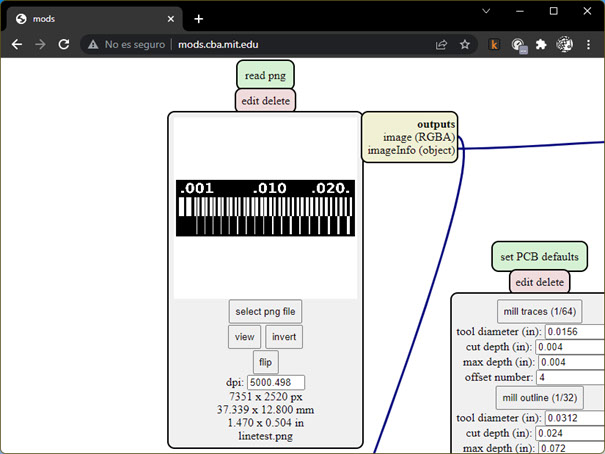
b. Load your png file into mods by selecting the first process:
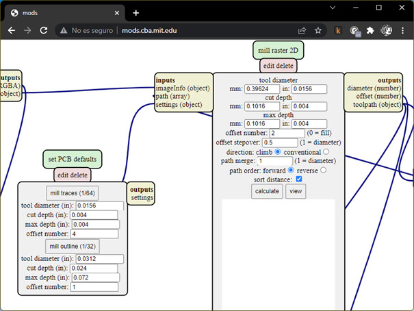
c. Select within the Set PCB defaults process if you want to mill the traces (1/64) or mill the outline (1/32). Then modify the particular parameters for your work in the mill raster 2D process:
- Tool Diameter: (we used 1/64”)
- Cut depth (in our case we made several tests with depths ranging from 0.002 in to 0.004 in).
- Offset number (the number of mills done around the shape).
- Offset stepover (to set the overlap of the number of traces set above).
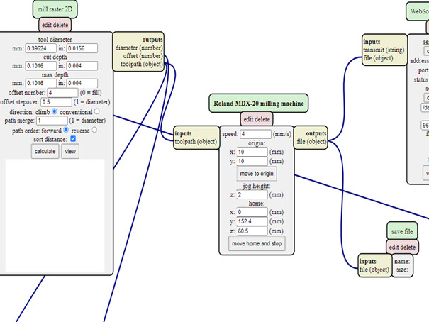
d. In the Roland MDX-20 milling machine process, select the parameters that you want your machine to use:
- Speed (ranging from 0.1 to 15, we made tests from 0.8 to 4).
- Origin (if you want to offset from the origin point).
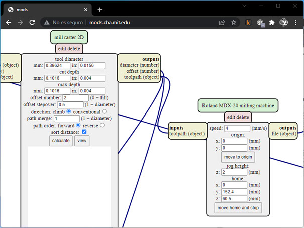
e. In the mill raster 2D process, click on Calculate, so the process runs and shows you the instructions you will be giving to the milling machine.
f. As we have already created the saving process, our file will be automatically saved in our downloads folder.
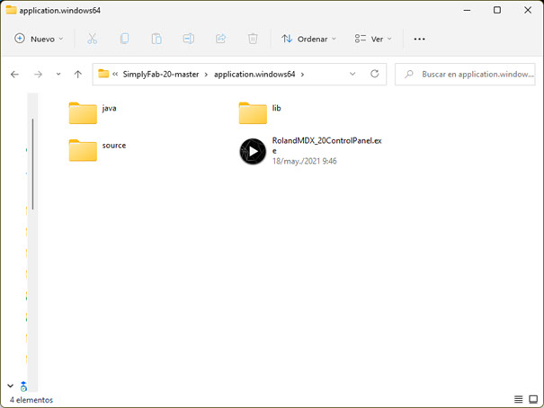
3. To control the machine, we will be using a custom compiled software made for the Fabacademy, you can download it from here: https://github.com/EDUARDOCHAMORRO/SimplyFab-20 . Once you plug the machine via the USB COM port to your PC, you will only need to open the exe file and start moving the milling machine,
https://github.com/EDUARDOCHAMORRO/SimplyFab-20
Continue by following the next steps:
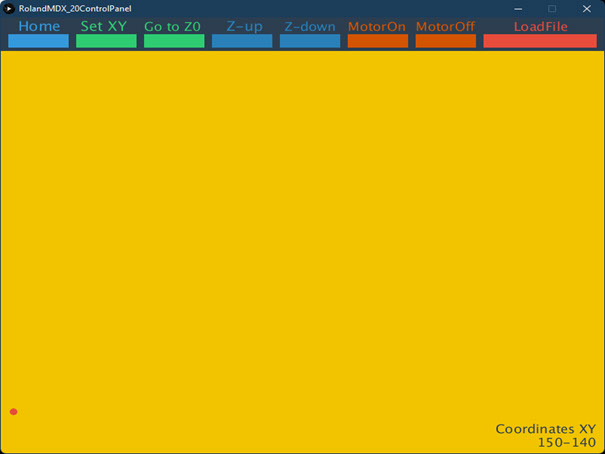
- Turn on the milling machine and click view to exit the viewing mode (it goes back there every time you turn on the machine.
- Click on the yellow area to set the origin coordinates. Click just once and wait for the machine to move to the next step, if you don’t wait the machine will move in the sequence you told it to, it can become a time-consuming process.
- Once you get the machine origin to where you want it, just click on the Set XY green button above.
- To set the Z position, you should use the machine buttons to get close to the board, once you’ve done that, make the final move manually by unfixing the cutter and move it down until it touches the surface of the plate and fixing it back there.
- Select your file with the Load File button and press enter to start cutting. The machine won’t wait for further instructions, it starts immediately.
4. After the milling process is done, you should have your board ready with the design you sent.
Parameters to be used:
For the next boards to be milled, we concluded:
- Tool diameter: 1/64”
- Cut Depth: 0.004 in.
- Offset number: to be defined by application.
- Offset stepover: 0.5
- Speed: 0.8 for milling (if we use a higher speed while using the 1/64” cutter, chances are that it will break).
- Origin: x=0, y=0