Task to be carried out this week
Action Plan
| Date | Work Allocation |
| 6th April | Prof. Neil's Lecture on Computer Controlled Cutting |
| 7th April | Brain storming and Idea sharing |
| 8th April | Idea conception, initial planning and work distribution |
| 9th April | Reading and research on the building PCB milling machines |
| 10th-11th April | Design and cuttings |
| 12th - 14th April | Assembly of design cutouts |
| 14th - 16th April | Electronicss |
| 17th - 20th April | Machine Assembly, Testing and documentation |
Idea Conception and Planning
For this week's assignment, we had to work in groups to make a functional machine that incorporated mechanism, actuation and automation.
In our fablab we have 11 people who are currently taking the fab academy course. The group was initially divided as 5 people in one group and remaining 6 in another group, Sadly, 4 of them test positive for COVID-19 so we had 7 in our group and the 4 of them worked as another team.
All seven of us in our group had different educational background, some were from architecture, some from electronics and some from education and commerce. Myself, I have an IT background. So according to our individual backgrounds, we dividied the tasks.
The first thing we did was brainstorm on what to make. We gathered and pitched our ideas.
Finally we decided to make a PCB milling machine for this week's machine making week. This idea came from the problem when milling our PCB on the current PCB milling machine. The bed level on the current Roland- SRM20 machien that we are using had become uneven. DIe to this we faced a number of problem when milling our PCB for output week.
This also caused for the loss of a number of copper plate.
Once we all agreed on the idea, the next step was to explore on how to build the machine. Since we do not readily get the electronic components in our country, we had to ensure that all the electronics we required were available in the lab. For this we had to dismantle a couple of previously made machines.
We gathered all the electronics we required and then started with the work. Our group had 7 members, thus we divided the tasks for efficiency. Two people were allocated for designing the components, 3 for electronics and 2 for documenting the entire process.
For the assembly and testing the machine, we all worked together.
My Contribution: What I did during this week.
One of the main task assigned to me this week was to document as we went along building the machine. So, most of the time I was with my phone capturing pictures and videos for the final documentation. Aside from the documenataion, I also did some designing works and programming.
Designing
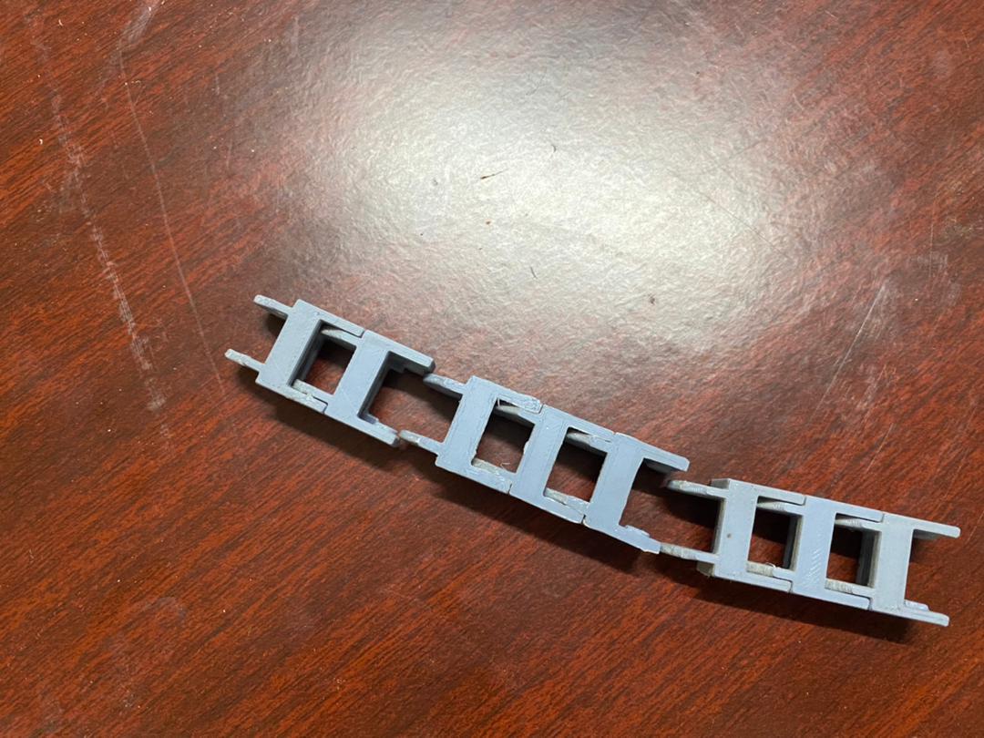
For the machince we were making, we needed a number of parts to be 3D printed. One of them was the wire holder. I designed the wire holder using the Fusion360 software.
The designing work is as shown below;
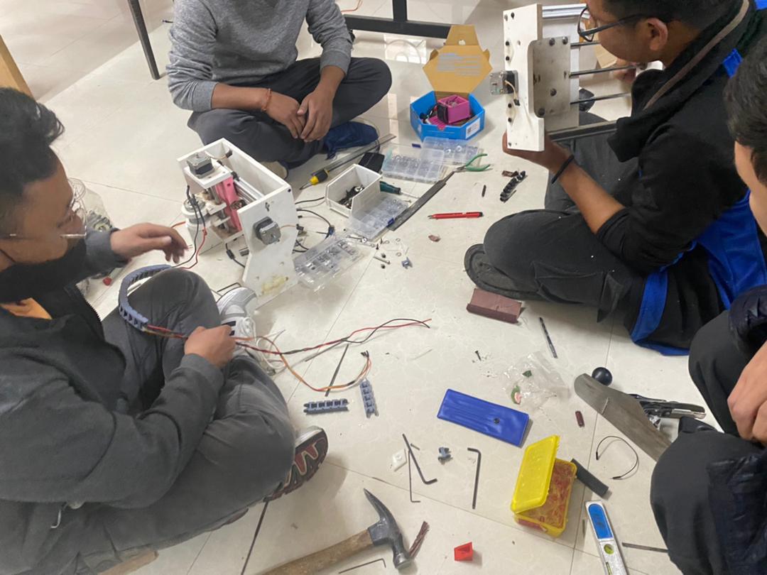
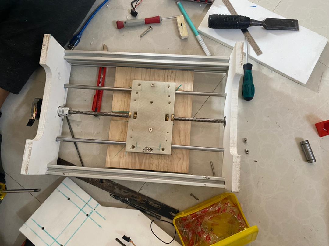
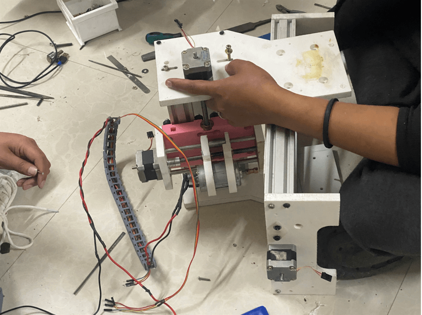
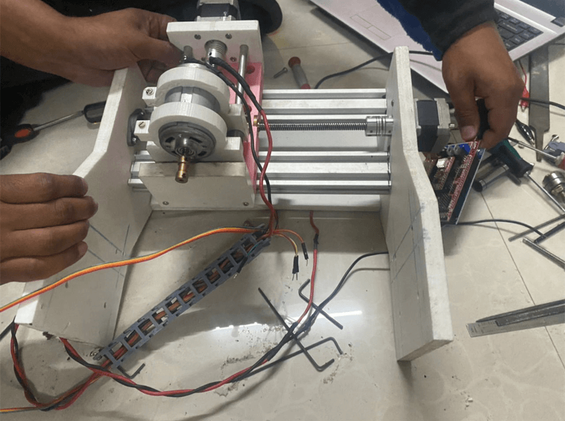
Machine Assembly
When it came to the assembly of the machine, all the member were involved. While assembling the parts, we had to make adjustments on the alignment. The drill holes we initially made were not aligned so we had to adjust them. We laso had to align the milling bed.
The following picture shows the assembly process.
Testing
When it came to testing the machine, there were 3 major testing we had to carry out out namely;
Documentation
The final task to be done once the machine was designed, built and tested was to document. As mentioned above, my main tas in the group was to capture all the process and dcoument them in the group page.
Documentaion included not only documenting the process in our group page but all making a final presenation video for the group presenatation. To make the presenatation video, initially I used the iMovies software on my phone but I found the software a bit rigid to use.
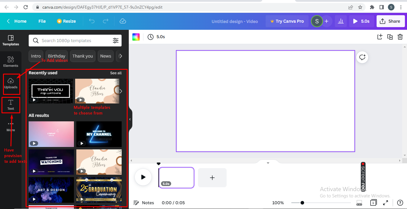
Hence I opted for an online video editor site called Canva.
Canva is an online video editing site that has anumber of free templates to choose from. It also had options to add background sound/music, texts and stickers/elements.
I found the site very user friendly and for a beginner in video editing, the site was very easy to use.
I used visual studio Code software to document the entire process of the machine building week.
The link to the documentation can be found here.