Task to be carried out this weekGroup Assignment
Action Plan
| Date | Work Allocation |
| 16th March | Prof. Neil's Lecture on Embedded Programming |
| 17th March | Reading and Understanding the datasheet of ATTiny 44 |
| 18th March | Reading and Understanding the datasheet of ATTiny 44 |
| 19th March | Documentation |
| 20th March | Programming my echo-hello board using Arduino IDE |
| 21st March | Documentation |
| 22nd March | Documentation |
Introduction to Embedded Systems and Microcontrollers
System: A system is an arrangement in which all its unit assemble work together according to a set of rules to perform ore or more tasks.
Embedded system: As the name suggests, embedded means one thing being attached/fixed to another thing. An embeded system can be described as a computer hardware system having software embedded in it.
An embedded system can either be an independent system or it can be a part of a large system. Embeded Systems can also be defined as Microcontroller or microprocessor based system which is designed to perform a specific task
A microcontroller is a small and low-cost microcomputer, which is designed to perform the specific tasks of embedded systems The general microcontroller consists of the processor, the memory (RAM, ROM, EPROM), Serial ports, input/output (I/O) peripherals on a single chip. It is also known as an embedded controller or microcontroller unit (MCU).
| Microcontroller | Microprocessor |
| Microcontrollers are used to execute a single task within an application. | Microprocessors are used for big applications. |
| Its designing and hardware cost is low. | Its designing and hardware cost is high. |
| Easy to replace. | Not so easy to replace. |
| It is built with CMOS technology, which requires less power to operate. | Its power consumption is high because it has to control the entire system. |
| It consists of CPU, RAM, ROM, I/O ports. | It doesn't consist of RAM, ROM, I/O ports. It uses its pins to interface to peripheral devices |
Source:tutorialspoint
Types of Microcontrollers
Microntrollers can be divided into various categories based on memory configuration, bit configuration and instruction sets configuration.
Types of Microcontroller based on Bit configuration
AVR was developed in the year 1996 by Atmel Corporation. The architecture of AVR was developed by Alf-Egil Bogen and Vegard Wollan and the name was derived from its developers and are also known as Advanced Virtual RISC. AVR Microcontrollers are available in 3 categories;
Comparison between the 3 types of AVR microcontrollers:
| Series Name | Pins | Flash Memory | Special Feature |
| TinyAVR | 6-32 | 0.5-8 KB | Small in size |
| MegaAVR | 28-100 | 4-256KB | Extended peripherals |
| XmegaAVR | 44-100 | 16-384KB | DMA , Event System included |
Atmel ATtiny 44
The first part of this week's assignment was to read the data sheet of the microcontroller used in the board that I am going to program.
Since, I am going to program my echo hello board and I used the ATtiny 44 microcontroller in my echo-hello board, I had to read the data sheet for ATtiny 44.
The datasheet was quite huge and with my near to zero knowledge in electronics, I found the document quite overwhelming. However, we had a session on reading the datasheet by the local instructor and that greatly helped me in understanding about the microcontroller.
I read the datasheet found on http://fab.cba.mit.edu and following are the information I learned.
ATtiny44 is a high performance, low-power CMOS 8-bit microcontrollers which is produced by Atmel Corporation.
They are a part of AVR mocrocontroller family and are based AVR RISC(reduced instruction set computer) architecture.
ATtiny 44 microcontroller has 14 pins, out of which 12 can be used for general purpose I/O lines. They have a 4KB flash memory with 256B EEPROM and 256B SRAM.
Some Features of ATtiny 44 are as follows;
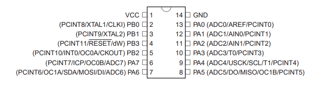
Pin Description
| Pin Number | Name | Description |
| Pin 1 | VCC | Power Supply |
| Pin 14 | GND | Ground |
| Pin 2 | PB0 |
|
| Pin 3 | PB1 |
|
| Pin 4 | PB3 |
|
| Pin 5 | PB2 |
|
| Pin 6,7,8,9,10, 11,12&13 |
Port A (PA7...PA0) | Port A has alternate functions as analog inputs for the ADC, analog comparator, timer/counter,SPI and pin change interrupt |
Programming my echo hello board
The next assignment for the week was to program our microcontroller board using the FabTiny ISP. I had already programmed my echo-hello board using Arduino UNO during the electronic design week. However, I had not tried programming with FabTiny ISP. So for this week's assignment, I tried programming my board using the FabTiny ISP I made in week 4. Before I began with the programmming, I made a SPI connector to using ribbon cables and 6-pin IDC for connecting the FabTiny ISP to my echo hello board. I checked the pin numbers on my board, FabTiny ISP and IDC connector and made the connections accordingly. Since I blew up the fuse on my FabTiny ISP, I had to use Arduino board to supply power and ground line to my ISP and board. I connected them using jump wires.
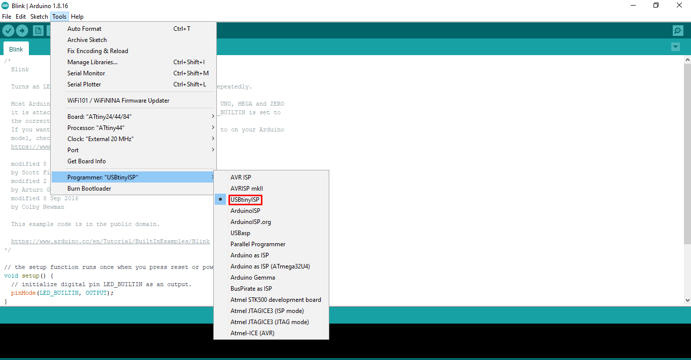
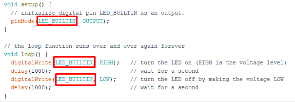
Next I had to install the driver for the FabISP. I downloaded the driver file from adafruit and installed it on my PC. I then used Arduino IDE to program my board. I followed the same steps as those I followed when I programmed by board using arduino UNO board. You can find the detail steps here: assignment week 6. The only thing I changed was the programmer. I selected FabISP as the programmer instead of Arduino.
Next I selected the blink program from the example. The LED is connected to pin 5 of my ATtiny 44 microcontroller and the corresponding pin in arduino is 8. Thus, I entered 8 in the program.
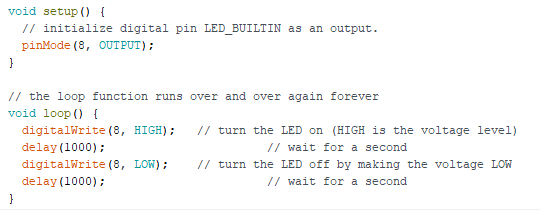
I compiled and uploaded the program and the result was as follows;
I also tried the button program from the examples. I changed the LED pin to 8, and button pin to 7. (pin 5 and 6 on ATtiny 44 microcontroller)