Task to be carried out this week
Action Plan
| Date | Work Allocation |
| 16th Feburary | Prof. Neil's Lecture and first review with Prof. Neil. |
| 17th February | Lecture on Electronic production and introdution to machine used in the lab by local instructors |
| 18th February | Group Assignment: characterize the design rules for our in-house PCB production process |
| 19th February | Reading materials on ISP and soldering. Reading fabacademy archives on the week's assignment to learn more. |
| 20th February | Designing and Milling the incircuit programmer (Brian Board) |
| 21st February | Soldering and testing the incircuit programmer |
| 22nd February | Documenting the weeks assignment |
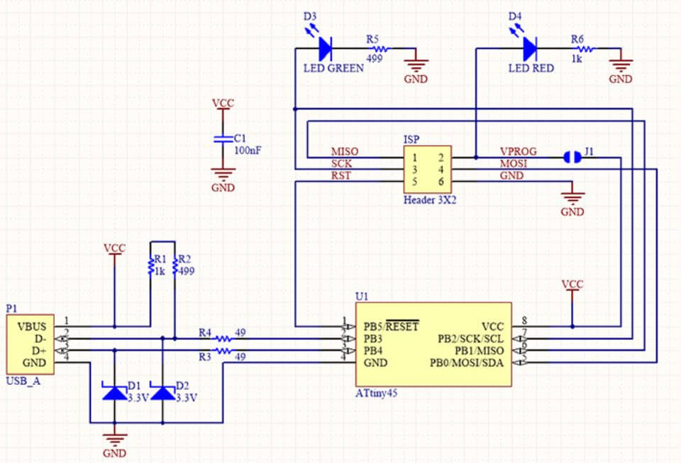
Introdution to ISP
In-system programming (ISP), or also called in-circuit serial programming (ICSP), is the ability of some programmable logic devices, microcontrollers, and other embedded devices to be programmed while installed in a complete system, rather than requiring the chip to be programmed prior to installing it into the system. The primary advantage of in-system programming is that it allows manufacturers of electronic devices to integrate programming and testing into a single production phase, and save money, rather than requiring a separate programming stage prior to assembling the system. Microcontrollers are typically soldered directly to a printed circuit board and usually do not have the circuitry or space for a large external programming cable to another computer.
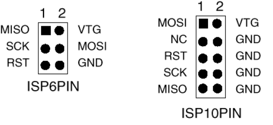
| Abbriviation | Name |
| MISO | Master In Slave Out |
| MOSI | Master Out Slave In |
| VCC | Power supply |
| SCK | Serial CLock |
| RST | Reset |
| GND | Ground |
PCB Milling Machine: Roland SRM 20
SRM20 is a low power, high precision and highly efficient desktop milling machine that is controlled through a touch-button VPanel controller to regulate feed rate, spindle speed and milling on a complete X, Y, Z axes, and an independent collet system that allows for faster setting of the Z-axis base point and quick tool changes.
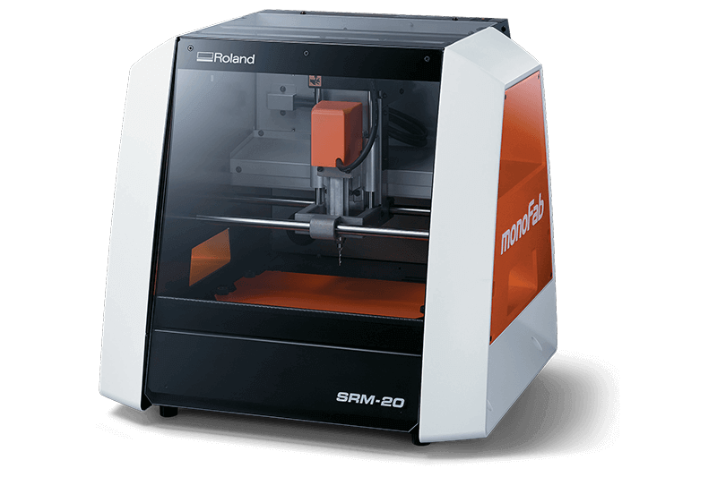
Roland SRM20.
(img source: https://www.rolanddg.eu/en/products/3d/srm-20-small-milling-machine/features)
PCB Milling Process
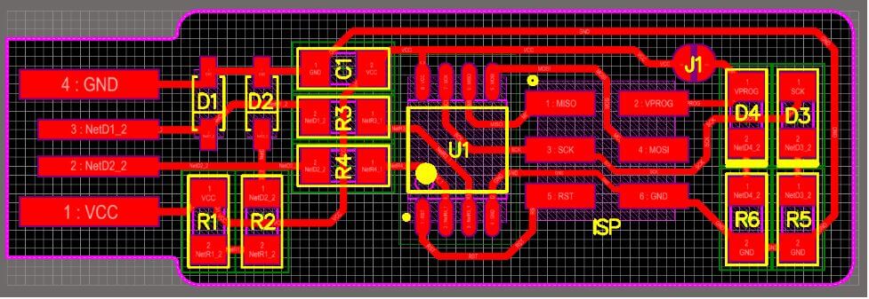
For my Fab ISP, I didn't make the design on my on but rather downloaded the design provided by fab academy called FabTiny ISP. I choose the brian's version of the ISP design.
Schematic diagram of FabTiny ISP
Board diagram of FabTiny ISP
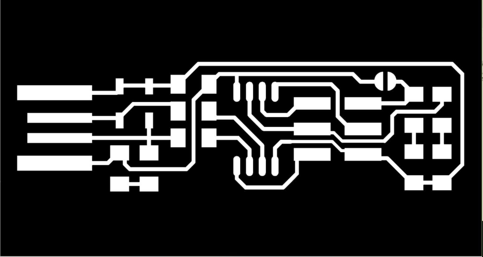
1.Download the monochrome PNG file for the in-circuit programmer
Download link: http://fab.cba.mit.edu/classes/863.16/doc/projects/ftsmin/fts_mini_traces.png
Download link:http://fab.cba.mit.edu/classes/863.16/doc/projects/ftsmin/fts_mini_cut.png
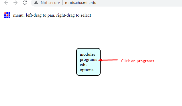
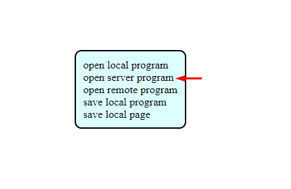
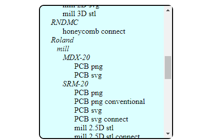
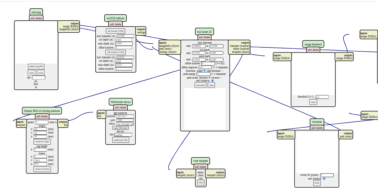
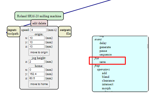
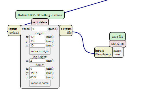
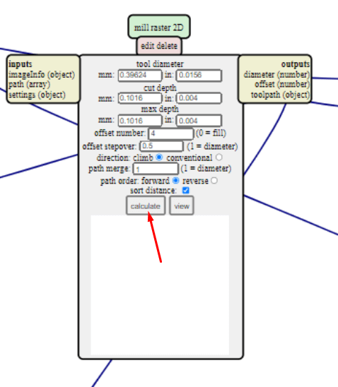
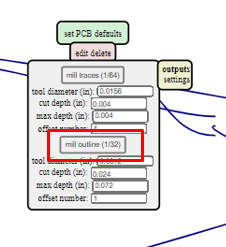
2. Converting PNG to RML file using MIT Mods.
Before we feed the ISP design to the milling machine, we need to first convert the PNG image into RML (Redline Markup Language) file which is a machine readible file format. I used the MIT Mods to convert my PNG design files into RML files.
I followed the following steps to create the RML file using MIT Mods;
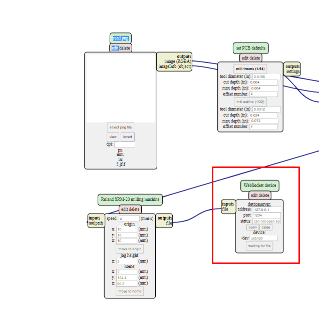
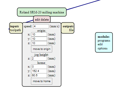
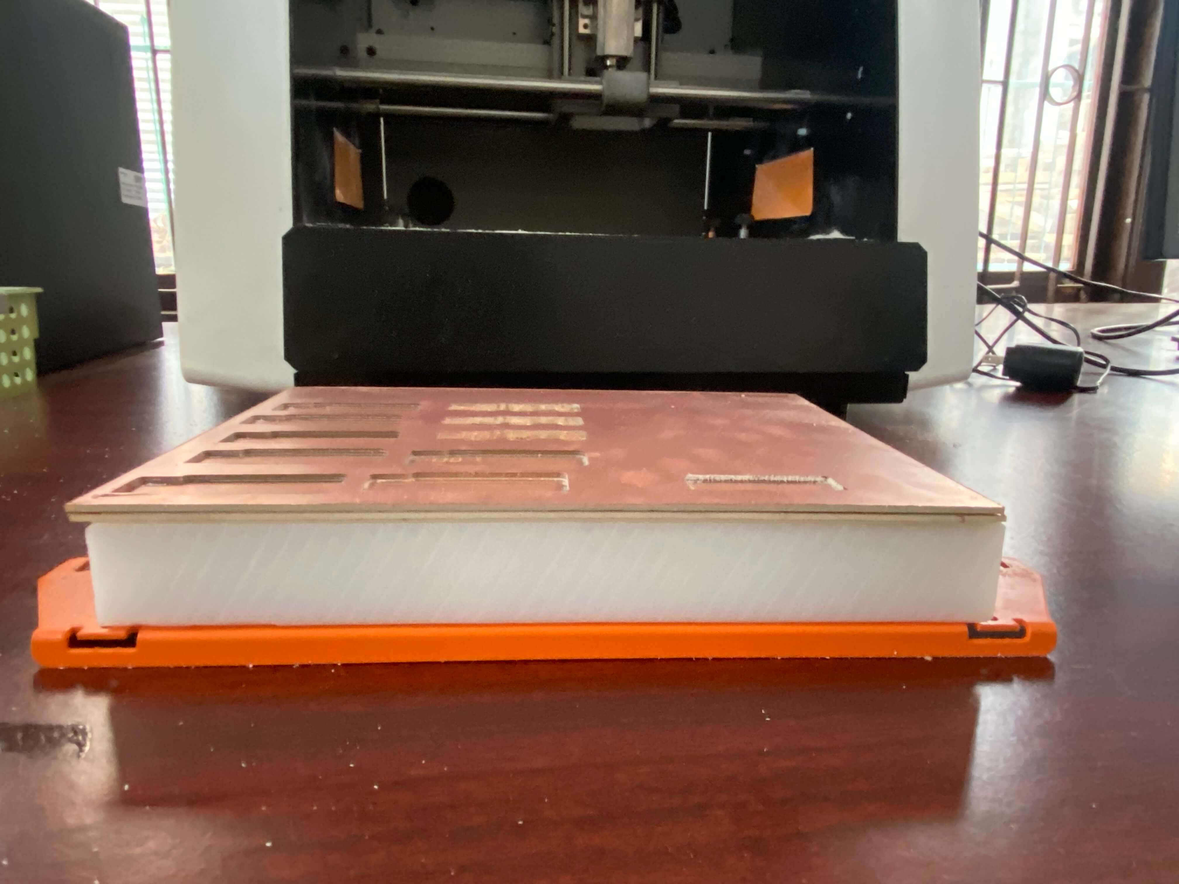
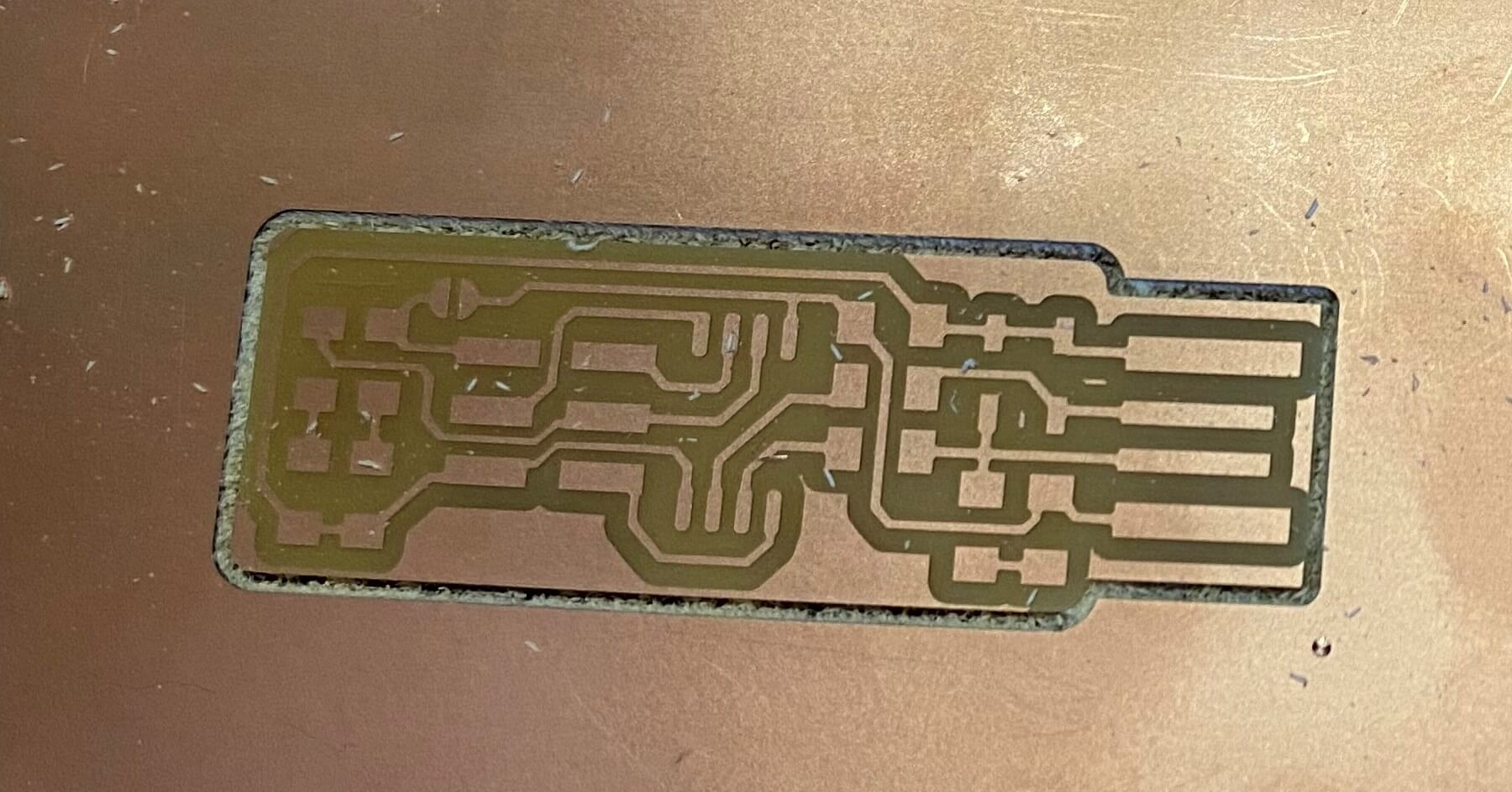
3. Roland SRM20 machine setup and PCB milling
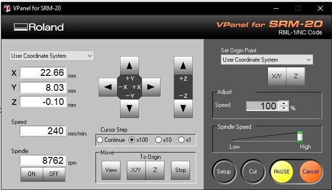
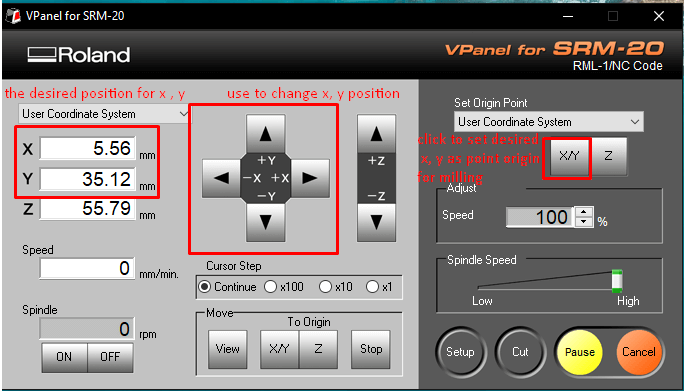
Once the rml files are created, we need to feed them to the SRM20 machine to mill our PCB. To do that, we use the VPanel which is a controller software that can be used to communicate with the SRM20 machine through as USB interface.
We need to carry out the following steps to mill our PCB.
Soldering
Soldering is a process used for joining metal parts to form a mechanical or electrical bond. Soldering uses a low melting point metal alloy (solder) which
is melted and applied to the metal parts to be joined and this bonds to the metal parts and forms a connection when the solder solidifies.
There are two types of solder used for soldering purposes;
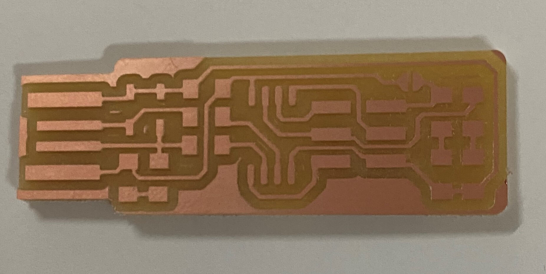
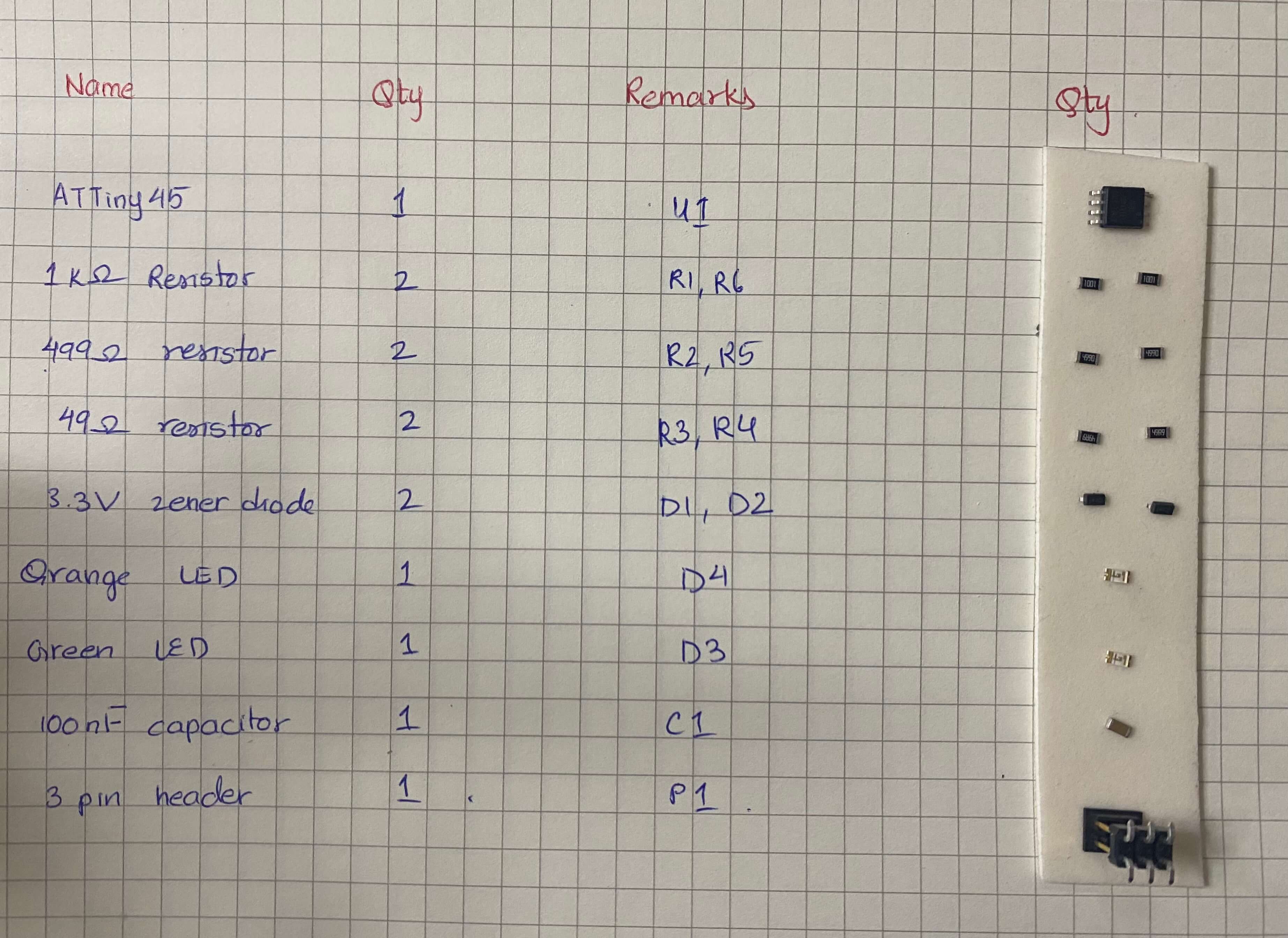
List of components that I soldered on my FabTiny ISP are shown in the image below.
I used the following tools when soldering the components on my PCB;
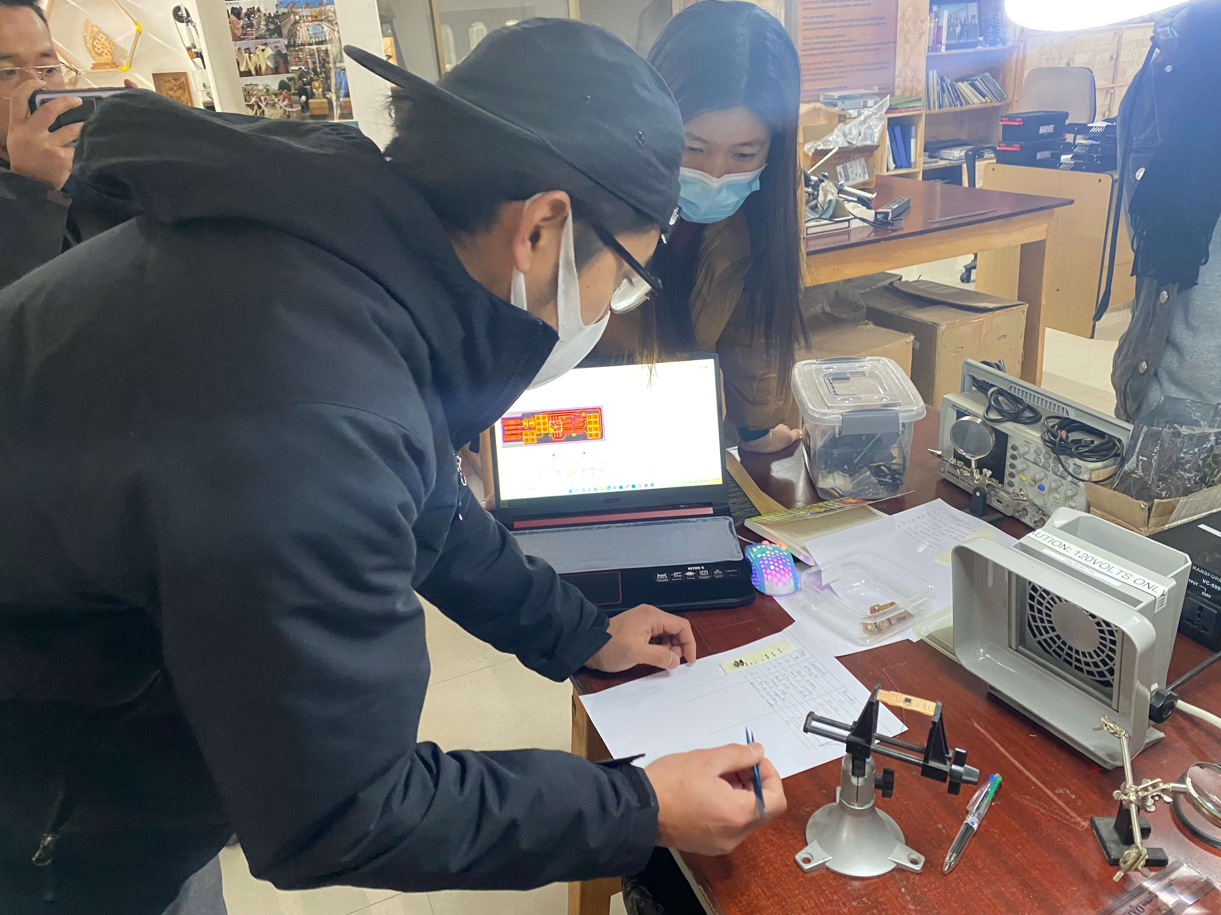
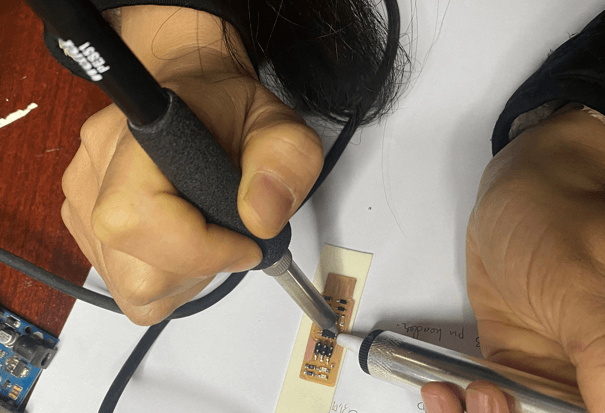
Demonstration on soldering by Mr. Take
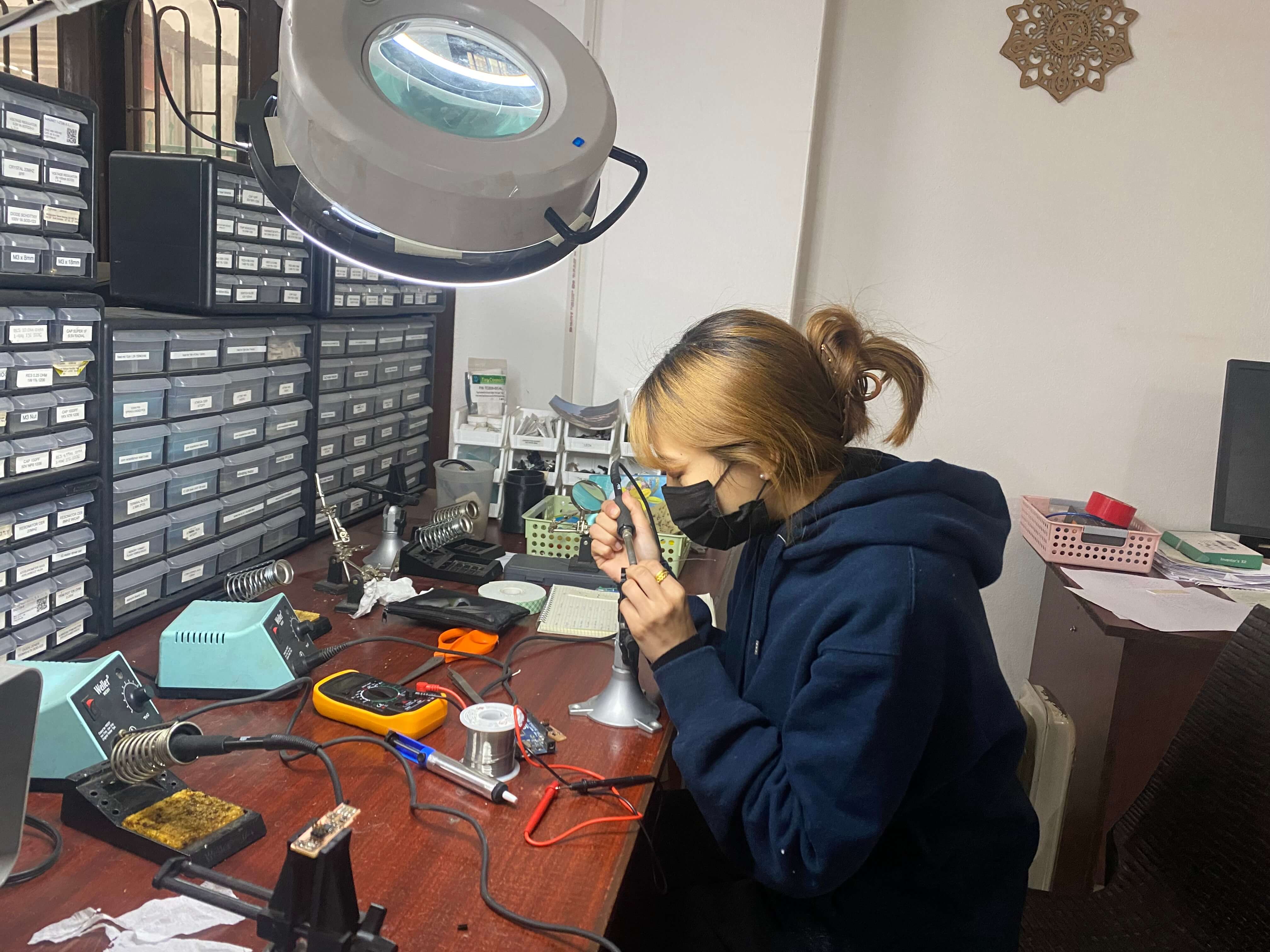
Once I had all the tools and components ready at the soldering station, I started with soldering. Since the components were tiny, it was quite difficult to solder. My hands kept shaking when trying to solder the components. Also, I made mistakes in identifying the polarity of the components when soldering, so I had to desolder the components and solder again.
This is the final ISP that I made. I went through a lot of mistakes beofore completing my soldering. I also burnt my hand by the soldering iron.
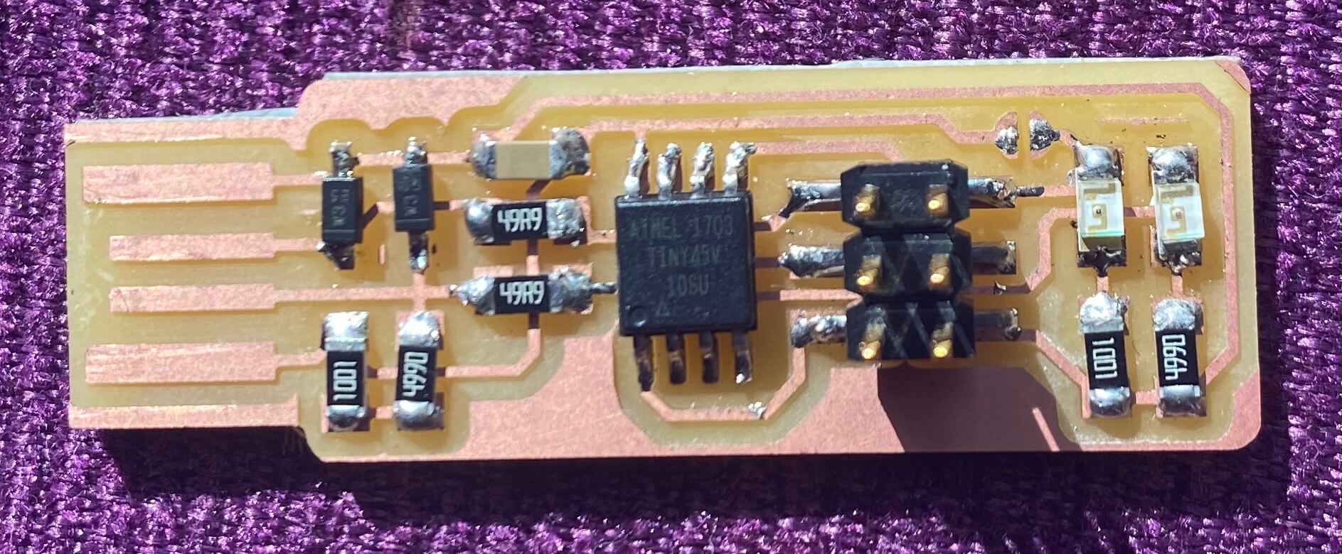
My FabTiny ISP
Programming the FabTiny ISP
Once we are done soldering, we need to program the FabTiny ISP using ISP programmer. To do that follow the following steps;
1. First download the firmware source code and unzip the file on the desired location.
2. Next we need to change the programmer type in the Makefile. We used the atmelice_isp to program the board. To do that, open the makefile available in the unziped firmware source code folder using a text-editor software. I used notepad++ text editor.
In the opened file, find the line that says:
PROGRAMMER ?= usbtiny and change usbtiny to atmelice_isp.
3. Now connect the soldered FabTiny ISP to the PC using a USB. The Red LED (orange in my case) will lit up if the soldering and commections are correct. Now, connect the
programmer to the ISP using the 6 pin connecter used on the FabTiny ISP. We need to ensure that the pin 1 on the connector matches up to pin 1 on the board.
4. Once the connection is made, run the following command on the terminal;
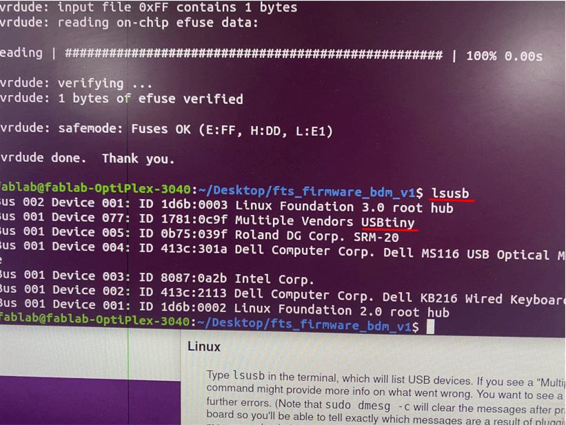
The ISP was successfully identified as shown above.
Removing the connection using desoldering tool.
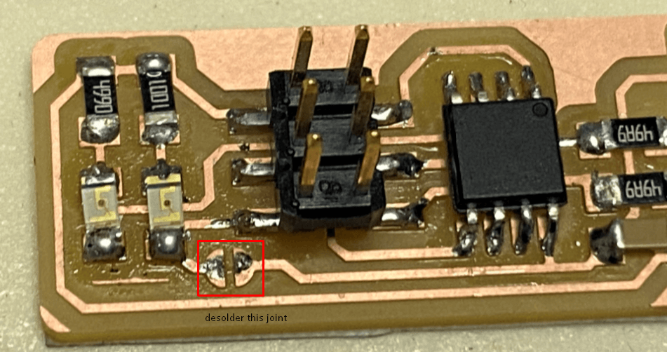
Successfully removed the connection.

.rml)