Controller board design
When it came to electronics for my project, the first thing I had to do was to read to learn about the the microcontroller and the electronic components I required. I fist thought of using attiny 44 microcontroller but dropped the idea when I found out that I can support very limited functionality and has limited storage space. Also, it had lesser number of pins than I requires. Next I thought of using ESP32 microcontroller but found that I won't be able to utilize the microcontroller to its full capacity and also, I didnt have any networking plans for my project. Thus, I decided to not use ESP32 as well. FInally, I discussed with the Fab instructors and as they suggested, I opted to use AtMega328P microcontroller.
Introduction to ATMega328P microcontroller
ATMega328P microcontroller is the one usually found on Arduino UNO boards. ATmega328P is a high performance yet low power consumption 8-bit AVR microcontroller that's able to achieve the most single clock cycle execution of 131 powerful instructions thanks to its advanced RISC architecture.
Parametrics of ATMega328P microcontroller can be seen in the image below;
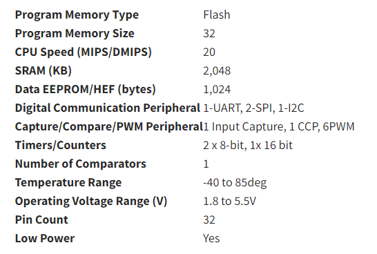
Source:https://www.seeedstudio.com/
Once I decided on the microcontroller to use, the next thing I did was to list down the electronic components I needed for my controller board. To do that, I had to first decide the number of inputs and outputs I wanted. Then, I had to check the pin connections for those input and output devices. As for my project, I had planned to add one input module and 2 output module namely;
Board milling and soldering
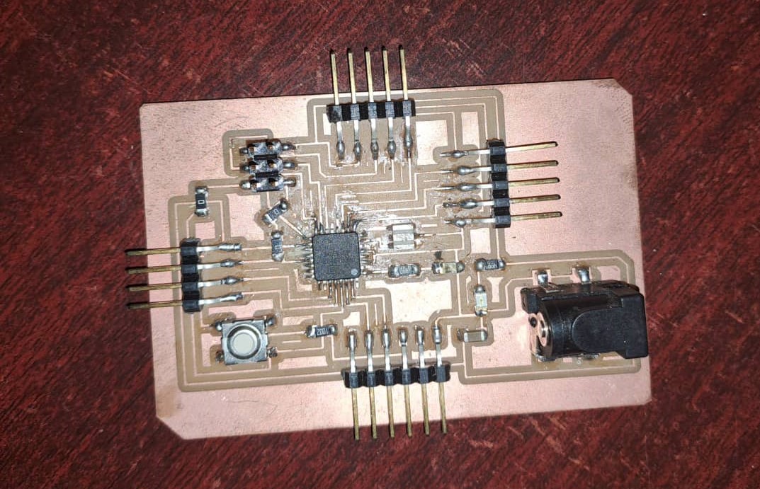
After the design was completed, I milled the board using the SRM20 PCB milling machine and soldered the components accordingly.
After soldering the final board is as shown below;
Input Device
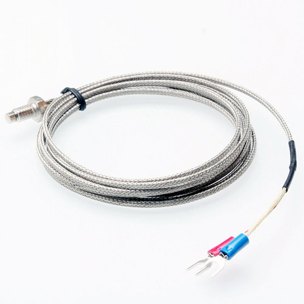
The input device for my project is a K-type thermocouple with a MAX6675 module.
K-type Thermocouple
K-type thermocouples are the most common type of thermocouple. They are made of Nickel-Chromium / Nickel-Alumel.
These thermocouplea are inexpensive, accurate, reliable, and has a wide temperature range. The maximum continuous temperature it can withstand is 1100 degree celcius.
Some of the features of the k-type thermocouple are listed below;
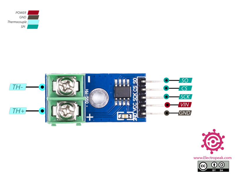
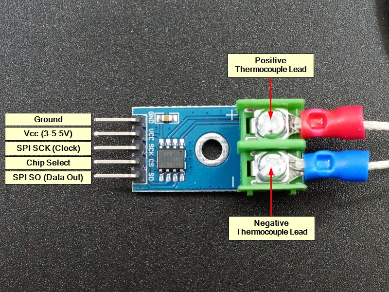
Connecting MAX6675 module to k-type thermocouple.
When connecting the K-type thermocouple to the MAX6675 module, the red head pin of the thermocouple needs to be commected to he TH+ of MAX6675 and the blue head pin needs to be connected to the TH- on MAX6675 module.
Output Devices
LCD with I2C module
For my project, I had two output devices. The first one is an LCD with I2C module.
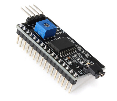
I2C module
I2C Module has a inbuilt PCF8574 I2C chip that converts I2C serial data to parallel data for the LCD display. The module comes in 2 default addresss namely; 0x27 or 0x3F.
There is a contrast adjustment pot on the underside of the I2C module and we can use this to adjust the screen to display text correctly.
Features of I2C module
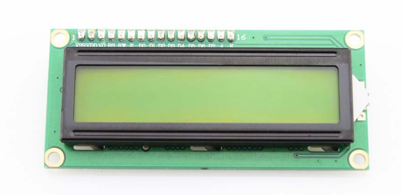
I2C Module for 16x2 (1602) Character LCD
I2C_LCD is an easy-to-use display module, It can make display easier. When you connect your microcontroller board directly to LCD, we require an 8 data pin connection while for connecting to an I2C we just need to make a 2 data pin connection.
This makes the wiring straight forward and board design work easier. The data pin connections required for the I2C_LCD display module are SDA and SCK.
Nicrhrome wire with Solid State Relay
The second output device for my project is the nichrome wire which will be the heating element for the kiln. The wire will be connected to the Solid State Relay which inturn is connected to the microcontroller Unit.
Nichrome Wire
Nichrome is a family of alloys of nickel, chromium, and often iron commonly used as resistance wire, heating elements in things like toasters and space heaters.
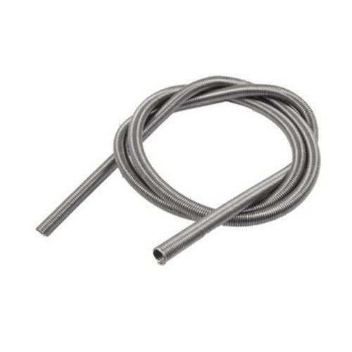
The nichrome wire I used for my project was had the following specification;
Solid State Relay
A solid state relay (SSR) is an electronic switching device that switches on or off when an external voltage (AC or DC) is applied across its control terminals.
SSRs consist of a sensor which responds to an appropriate input (control signal), an electronic switching device which switches power to the load circuitry, and a coupling mechanism to enable the control signal to activate this switch without mechanical parts. They may be designed to switch either AC or DC loads.
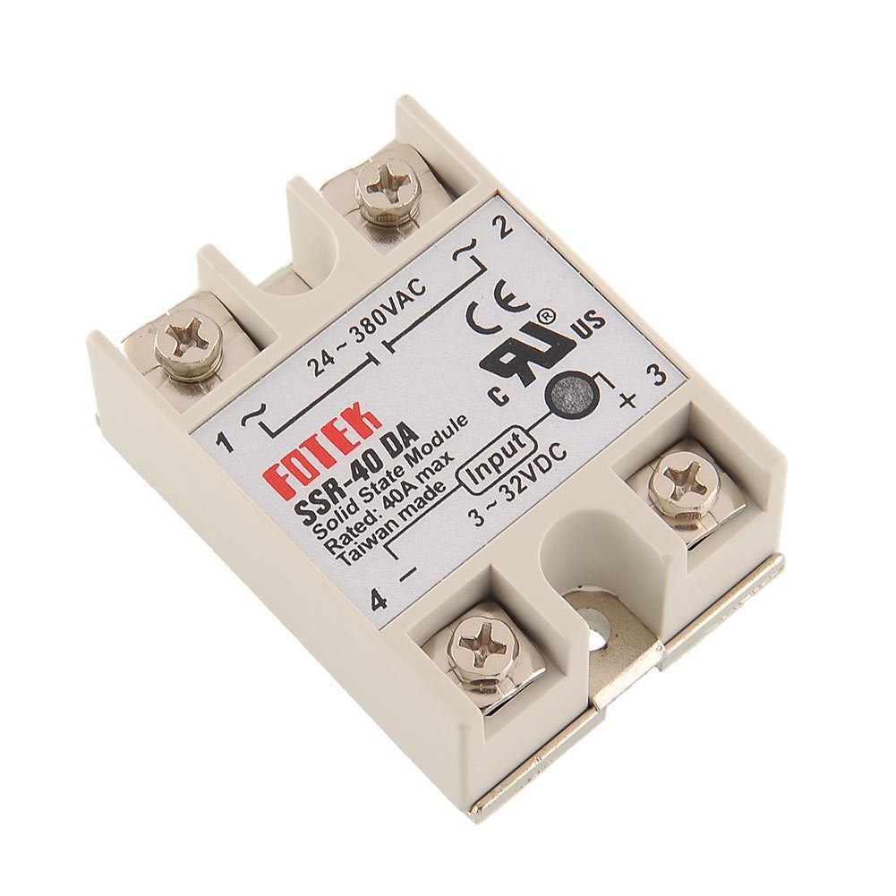
The specification of the Solid State Relay used in my project is as follows;
Connecting Relay to heating element.
The detail of the connection can be seen in the image below;
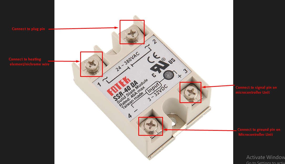
As shown in the image above, the VDC of the relay is connected to the signal pina nd ground pin of microcontroller unit and the VAC is connected to the nichrome wire and power plug.