COMPUTER CONTROLLED CUTTING
GOALS FOR THE WEEK
- Characterize our laser cutter machines and make test part(s) that vary cutting settings and dimensions.
- Document your work to the group work page and reflect on your individual page what you learned
- Design, lasercut, and document a parametric press-fit construction kit, which can be assembled in multiple ways. Account for the lasercutter kerf.
- Cut something on the vinylcutter
GROUP
INDIVIDUAL
GROUP ASSIGNMENT
For the group assignment, we decided to work in pairs and each take up a different material, produce templates and kerf tests to experiment with different values and settings to get comfortable with the machine. The group page is linked here
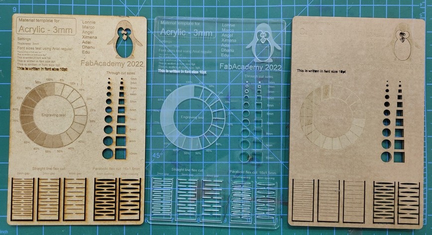
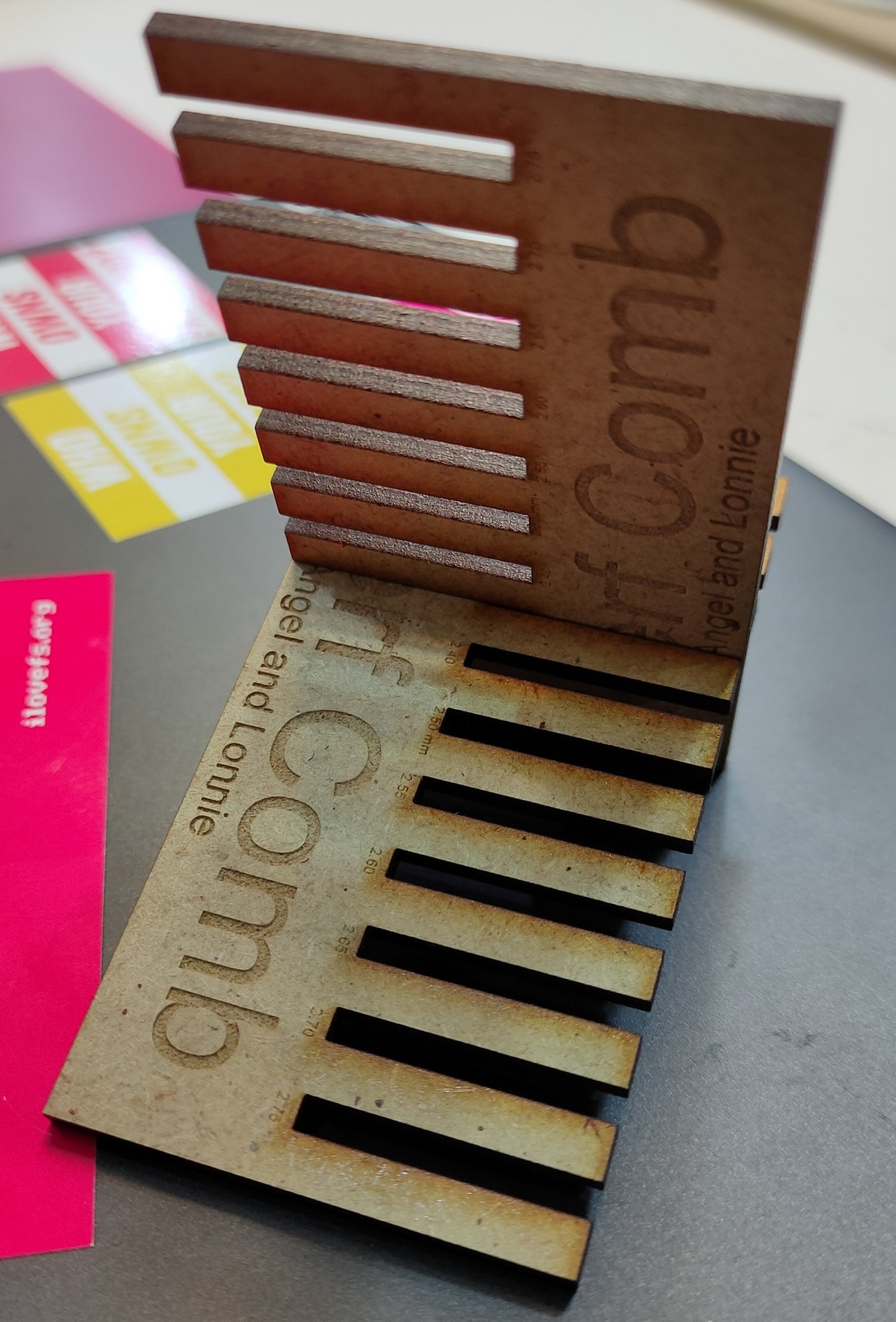
MDF 2.5 mm
Cut: P 55 / S 0.5 / F 1000Hz | Engrave: P 70 / S 100 / F 1000Hz | Raster: P 80 / S 50 / F 1000 PPI
Transparent Acrilic 3 mm
Cut: P 60 / S 0.5 / F 20000Hz | Engrave: P 70 / S 100 / F 20000Hz |
Raster: P 60 / S 100 / F 1000PPI
Plywood 4 mm
Cut: P 75 / S 0.5 / F 1000Hz | Engrave: P 65 / S 100 / F 1000Hz | Raster: P 60 / S 100 / F 1000PPI
VINYL CUTTER
SILHOUETTE CAMEO 3
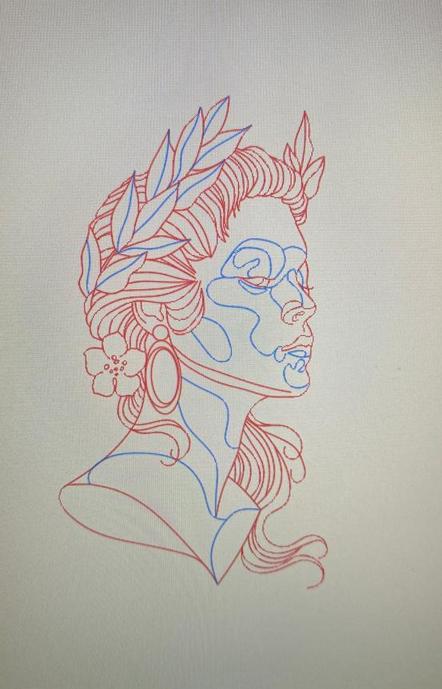
First, I converted a sketch into curves and polylines on AUTOCAD and made different layers for the two colours.
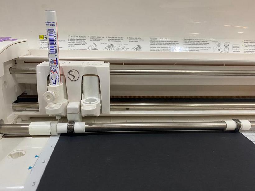
The fablab has a 3d printed part module that I could attach my pen to..
THE SOFTWARE
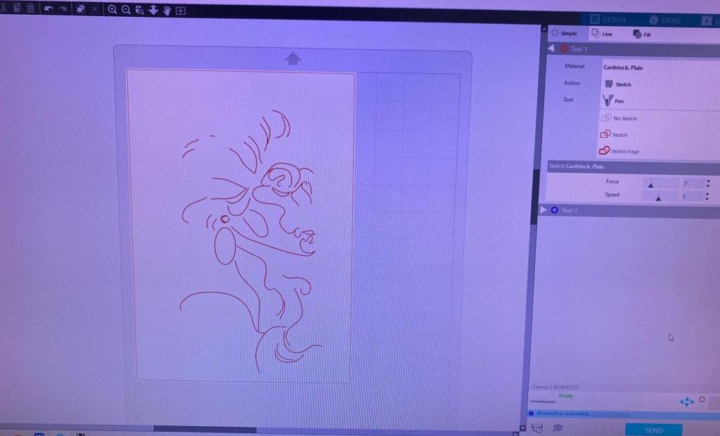
- Import .dxf file into cameo software.
- Select material as Cardstock plain.
- The tool is set to Pen.
- I had to experiment with the force and speed and go through a set of tests, eventually I set the
force - 7
speed - 5
PROCESS
- Make sure the tip of the pen is not too soft as it might bend under pressure.
- The file should contain only vectors.
- As I wanted to use 2 different colours, I had make seperate files for each and make sure to have the same origin.
- I used to sticky mat to hold my cardsheet in place.
- Feed the mat to the vinyl cutter through the rollers using the sticker indicator as a reference.
- Set the origin by pressing the "Origin" button on the control panel.


RESULTS
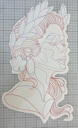
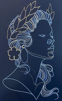
The accuracy of the sketch depends on strength and movement of the pentip.
LASER CUTTER
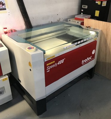
Trotec laser cutter is quite convenient to use. The setup in the lab uses Rhino + the proprietary Trotec interface to send the file to cut. So, to cut your file, you need a 2D curve that can be imported into Rhino. The traces need to be joined to make sure that there are no loose ends and double lines. Then you send it to Trotec and define the laser’s force and speed according to the material and thickness.
INDIVIDUAL PROJECT
PARAMETRIC LAMP
I decided to design a lamp in grasshopper that would adapt different forms with the change in a specific parameter.
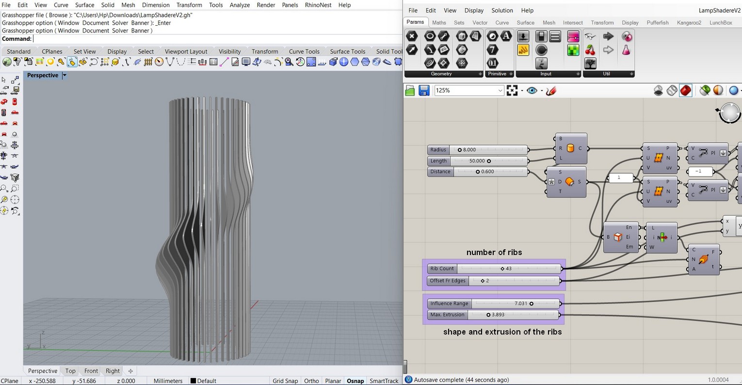
Gh defenition for the circular holders for the lamp. The number slider can be used to define the thickness of the material.
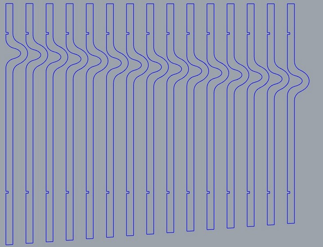
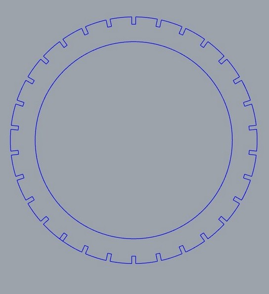
I then extracted the profile and made some changes to it. I also added the 2 circular holders. I accounted for kerf as 2% of the thickness.
SETTING UP THE MACHINE
- Check dimensions etc of the file to make sure it is ok
- Set up colors/layers to control cut order and group things that need the same laser settings
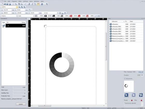
- Do file -> Print to the cutter job control software
- Look at the file in the job control software to make sure the dimensions etc are ok
- Set up the proper cut order using colors/layers
-
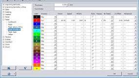
Cut:
3mm MDF: 55 Power, 0.5 Speed, 1000 PPI - Engrave:
3mm MDF: 40 Power, 2 Speed, 1000 PPI - Raster:
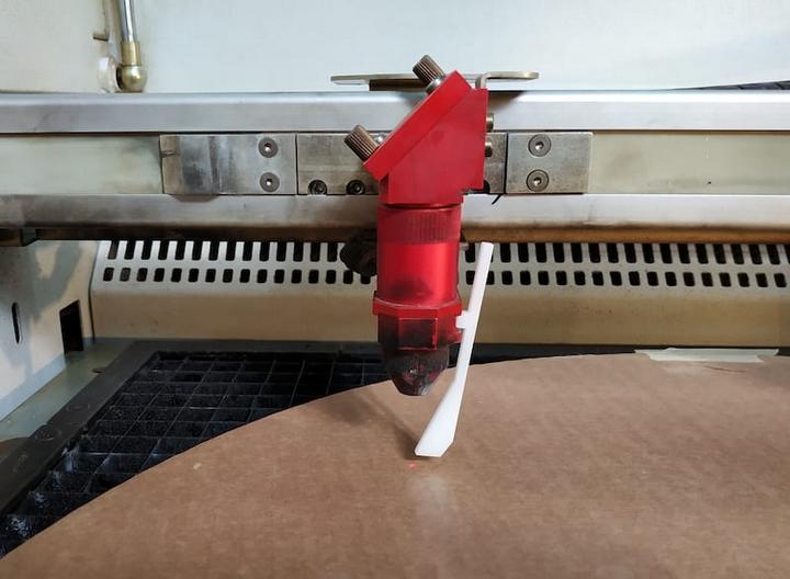
mm MDF: 70 Power, 80 Speed, 1000 PPI - Set up the focus and start position for the laser
- Check to see if the ventilation is on
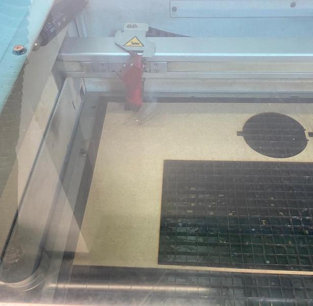
- Click on the run icon
-
The settings used are:
ASSEMBLY
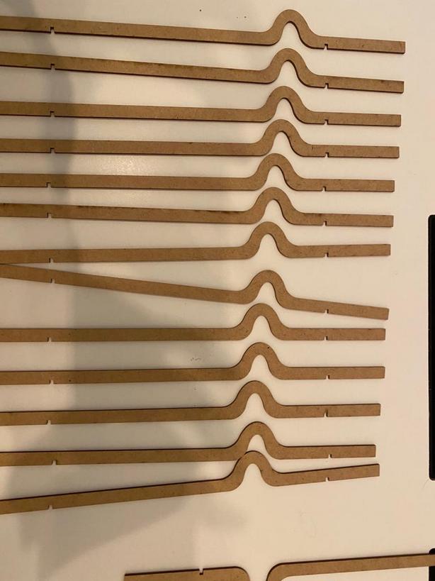
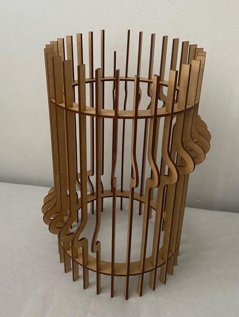
The pieces can be fitted on to the circular holders to either form the cascading pattern or create a completely new one.
BOOK COVER
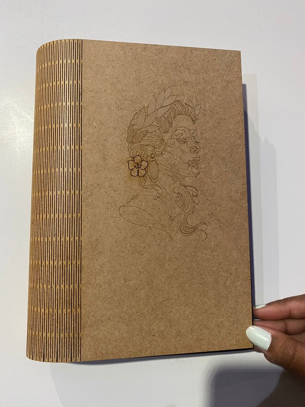
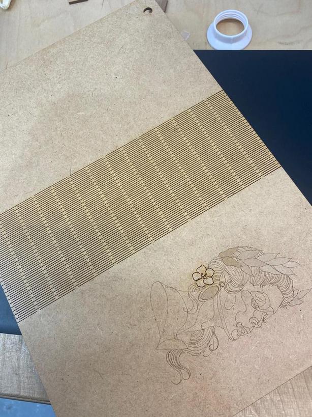
I also wanted to explore the concept of living hinges, so I made a design for a book cover using the same vector file I had made for the vinyl cutter.
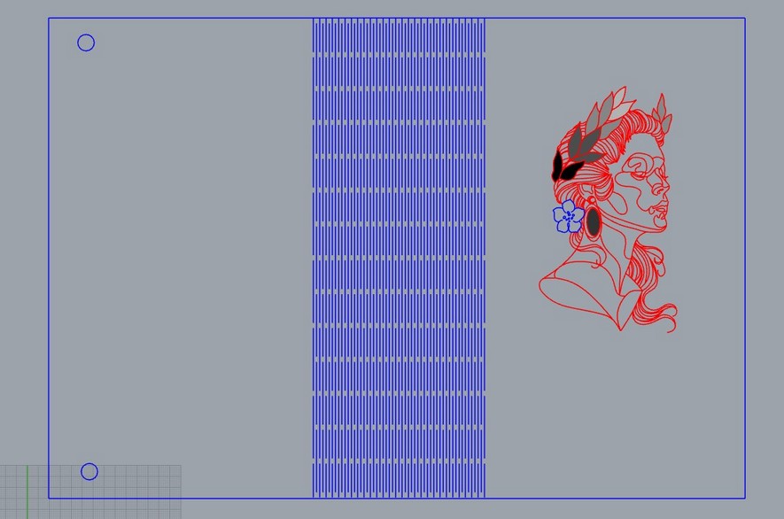
I used hatch in rhino to give the petals a color gradient to replicate it in the laser.
THE RESULT
Design files download
Vinyl .dxf file
Lamp Gh file
Lamp .dxf file
Book cover rhino file
