Electronic Design is a creative activity that allows the individual to put their ingenuity and creativity to work to
solve Electronic Engineering problems.
In the same way, the Electronic Designer implements new information processing strategies through the use of new components
and / or development of application-specific integrated circuits..
Assignment:
Group assignment
characterize the design rules for your PCB production process
Individual assignments
make an in-circuit programmer that includes a microcontroller
by milling and stuffing the PCB, test it,
then optionally try other PCB processes
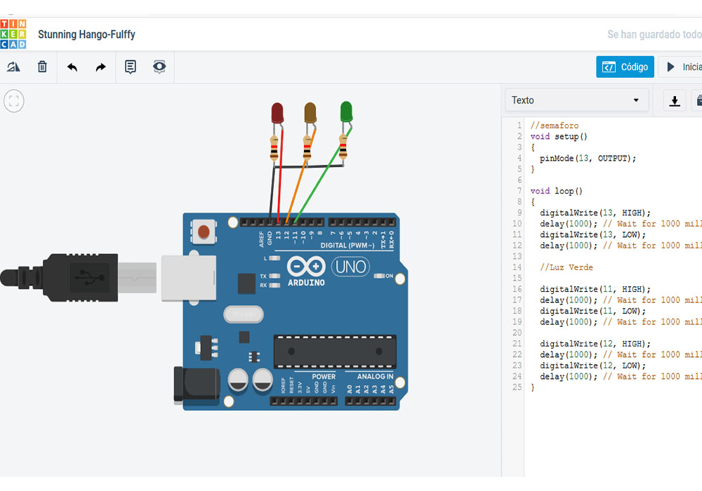
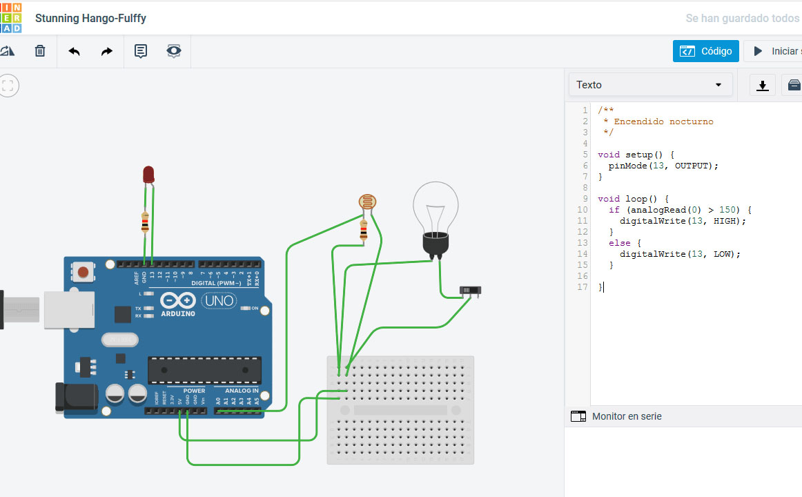
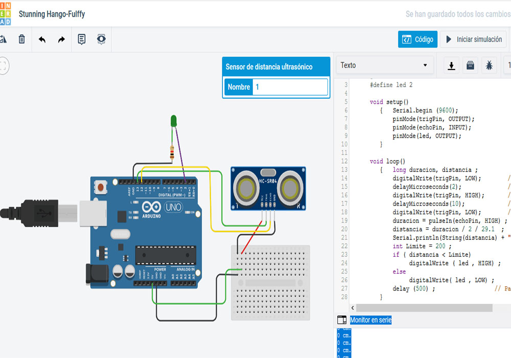
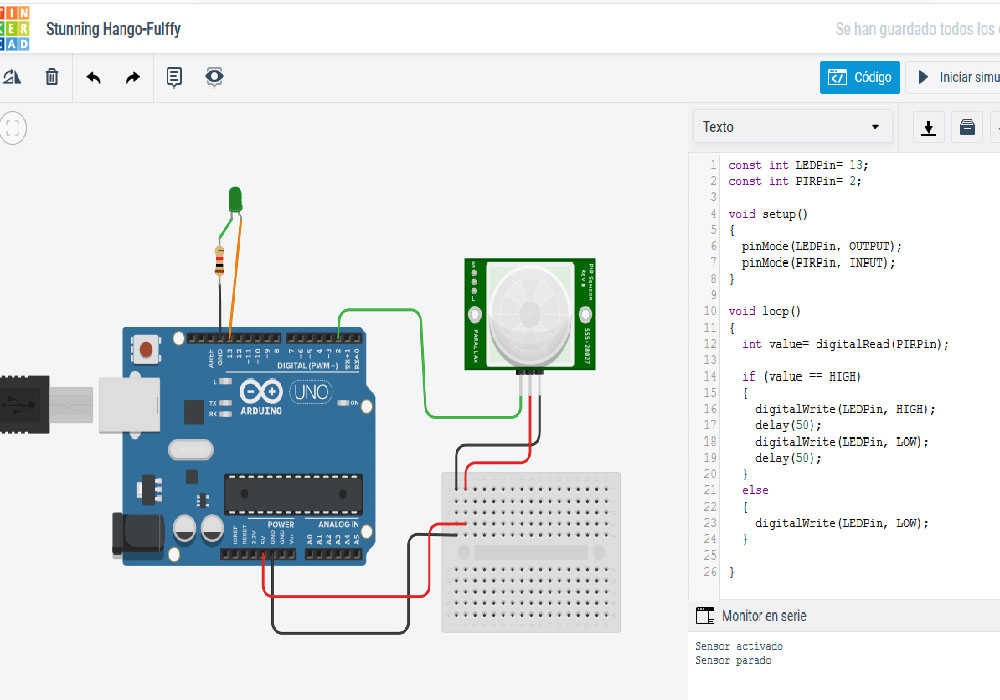
It was a practice in TINKERCAD to remember electronics principles, I put together several circuits using an
Arduino mega to connect LEDs, sensors and other components.
Practice in TINKERCAD
Trafic Light and Light sensor
Motion sensor and Proximity sensor
Starting manufacturing PBC Fabrication
As a second practice, the mods web application was used to create printed circuits from an image.
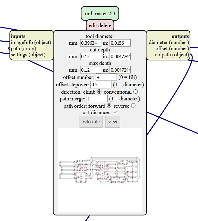
provides us with tools and the different parameters involved for the G-code mill 2D PNG program that has the following parameters:
Tool diameter: diameter of the cutter.
Depth of Cut - How much goes down the cutter.
Max Depth - The maximum limit to which the cutter will drop.
Offset Number - Number of steps the router will remove unwanted material.
Compensation Step: Percentage of the cutter diameter of the cutter will eliminate each step.
Direction: upload
Route fusion:
Route order:
Calculate: This button automatically generates and downloads the G code file for the CNC machine.
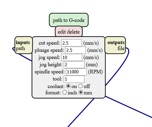
The second step was to check the G code node:
Cutting speed: Speed from one point to another
dive speed: how long does it take to go up and down
jog speed:
jogging height:
spindle speed: rotational speed.
tool: 1
coolant: on
After that, we downloaded the PNG Traces and Interior files to test the accuracy and configuration of our machine.
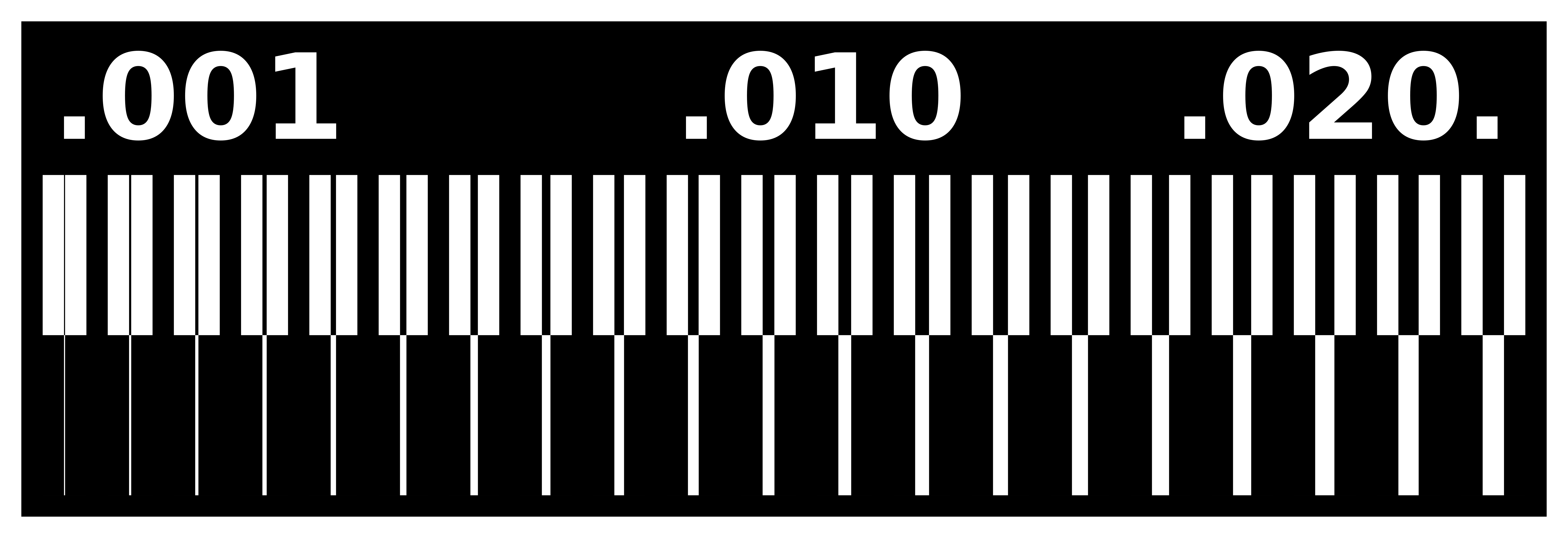
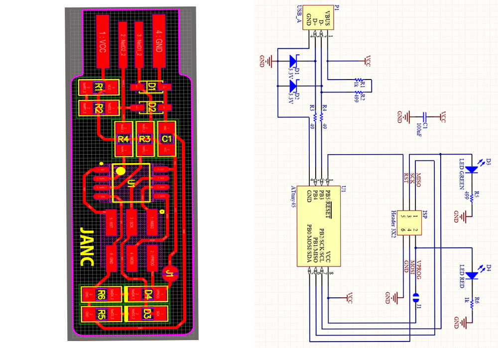
For this assignment we based the FabTinyISP. a PCB circuit already made and tested, to be able to
learn the use of the MODs the files can be downloaded from this link JANC PCB,and
fts CUT
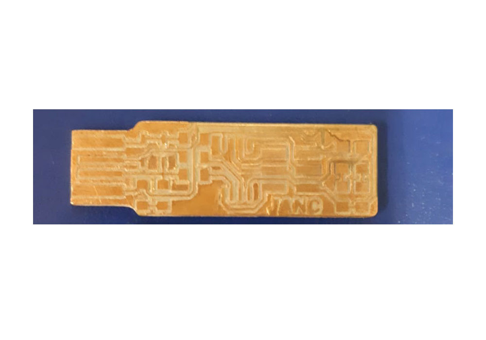
I customize my board with Paint in that way I add my initials to the board
Use MODS
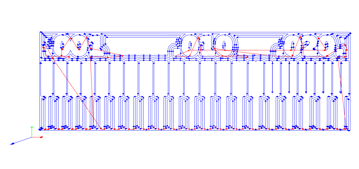
Once we had the file ready we used mods to generate the G/code. On mods follow this steps:
Right click, programs
Open server program
G-code
Mill 2D png
Below we show the basic configurations for the creation of electronic boards
for this we select the png file, and set the parameters for the mill raster and the
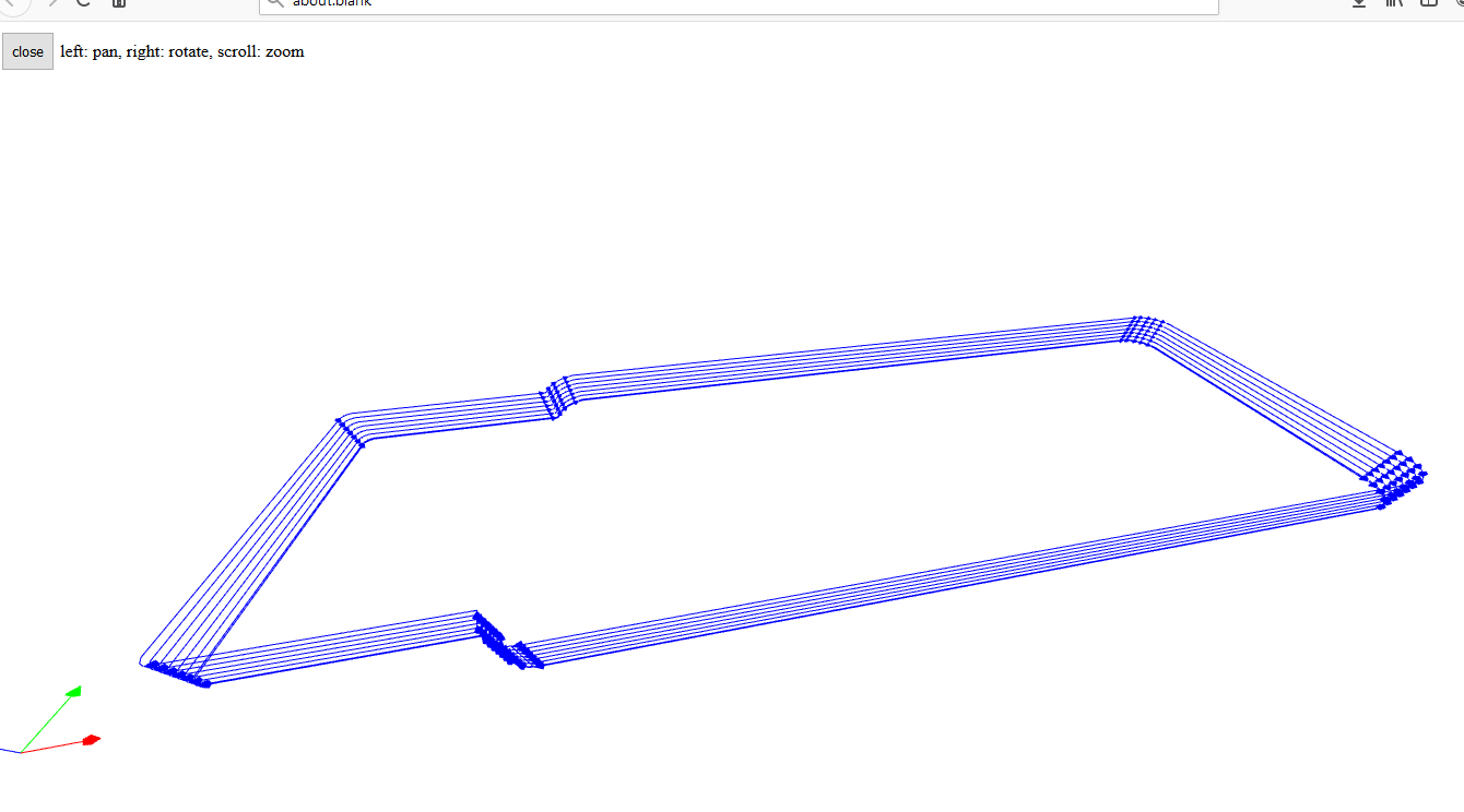
path for the G code. Then we proceed to calculate and as a result we obtain the simulation of the code in a pop-up window.
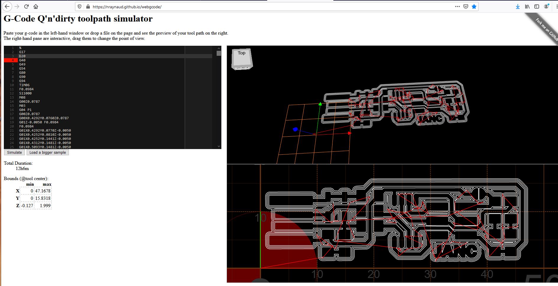
We can also use an online simulation with G-Code
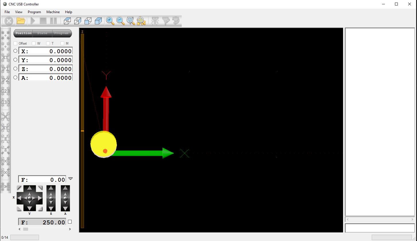
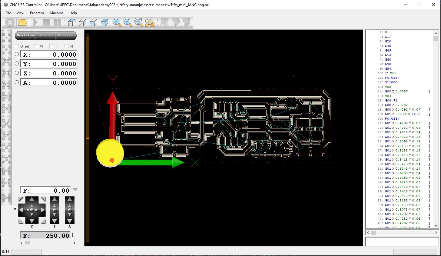
CncUsb
Once we obtain the g code from the MODs and after verifying that everything is fine with the gcode simulator,
I use the program with which I bino my desktop CNC Router, the program is the CncUsb, it is a fairly intuitive and
easy program to use, my cnc has no configuration for the revolutions that is controlled by an integrated
potentiometer, with which I have to calculate the ideal speed for milling
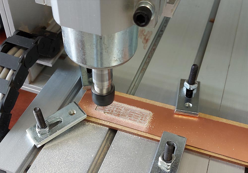
starting with the CNC milling
For the manufacture of the first pcb board, I sent the g code to Fablab ZOI in Quito, so that they could help me manufacture it.
The reason for this is that I am taking the course virtually from the city of Tulcán.
In the week of the assignment, I still did not have my cnc machine
because the import with which I bought it at the university where I work did not arrive,
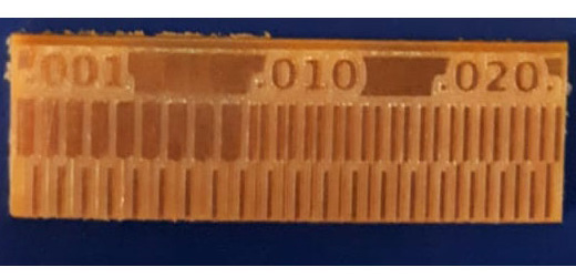
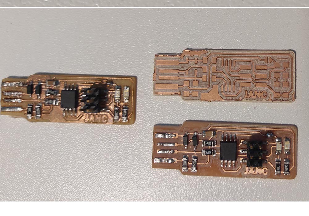
When the cnc arrived I manufactured
in my laboratory weeks later the second pcb board and now I am manufacturing a third to gain experience in its manufacture
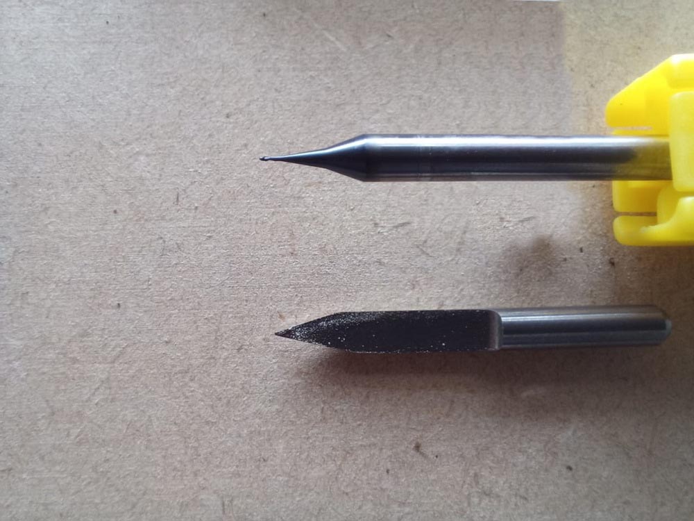
In this process of self-learning alone, I broke several Engravers, understanding the operation of the cnc, the most difficult thing was
understanding the zero point through the sensor, something very easy when you understand it after breaking several Engravers
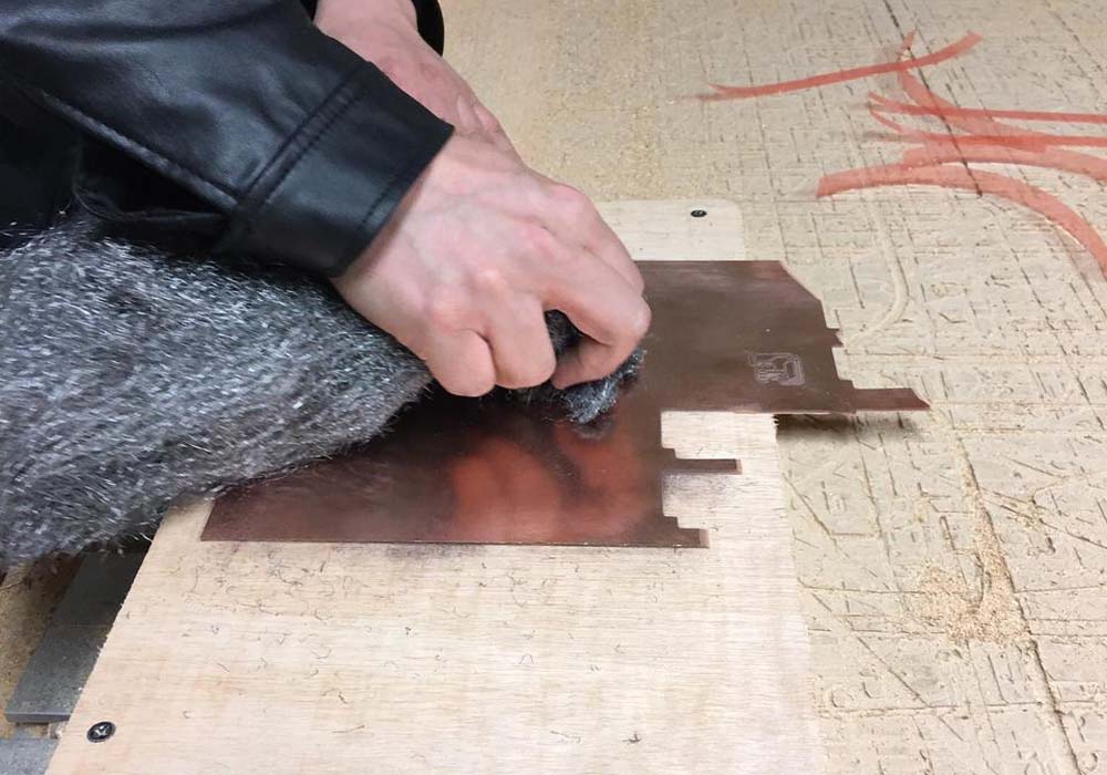
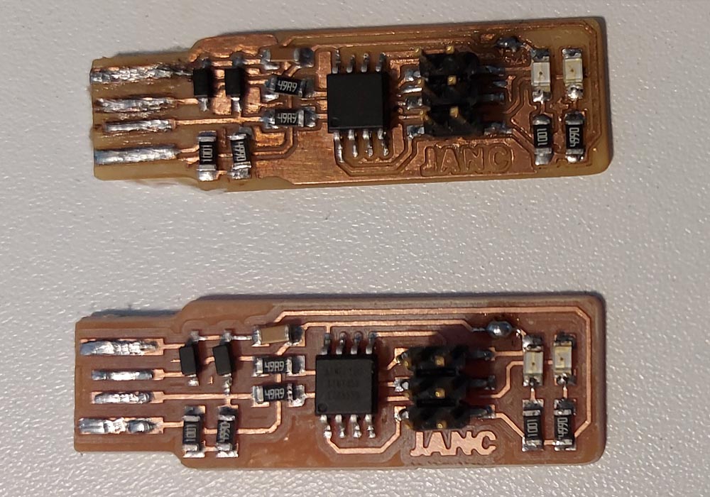
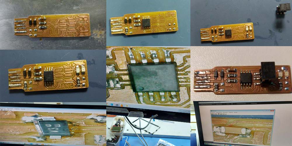
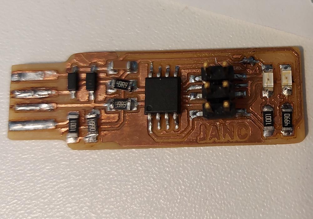
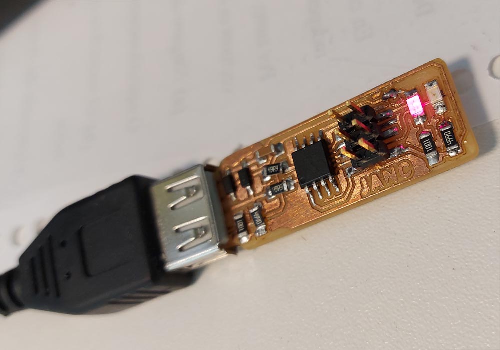
The board
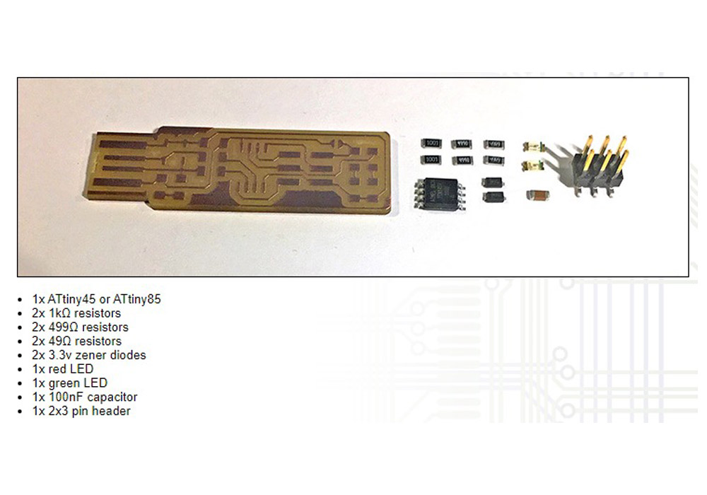
Below we can see the final result with the finished electronic board
1x ATtiny45 or ATtiny85
2x 1kΩ resistors
2x 499Ω resistors
2x 49Ω resistors
2x 3.3v zener diodes
1x red LED
1x blue LED
1x 100nF capacitor
1x 2x3 pin header
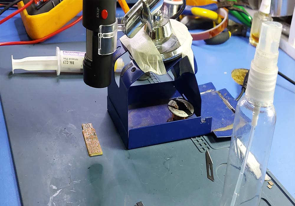
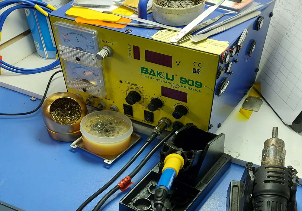
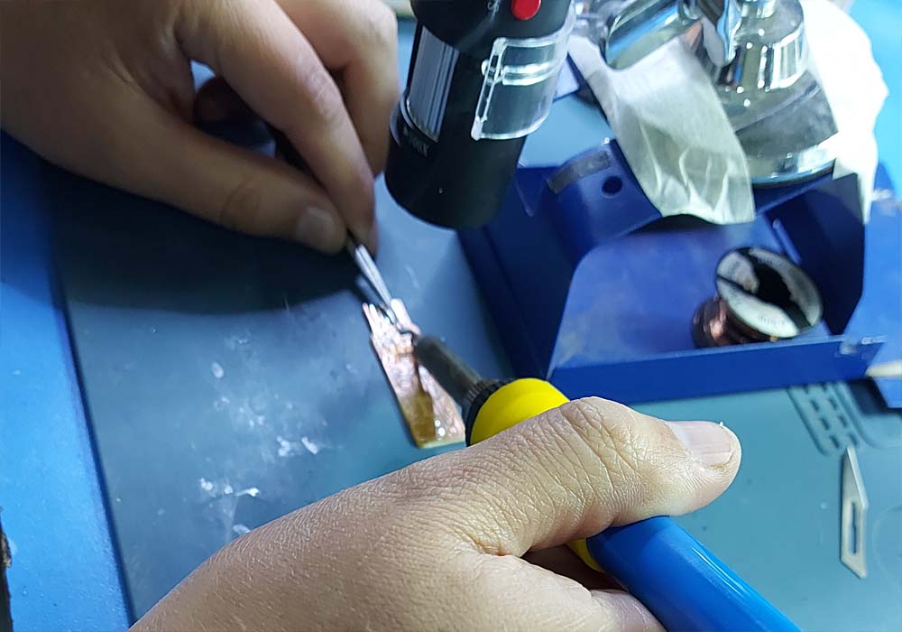
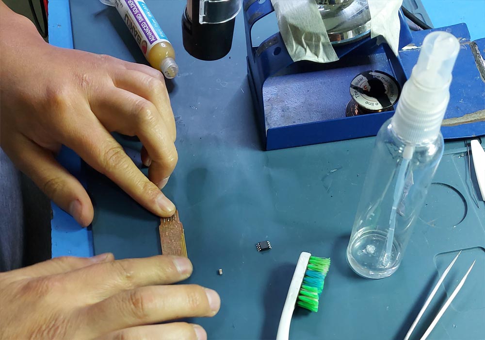
For the welding process, a Baku 909 welding station was used and as a support to weld the micro components,
a USB microscope endoscope camera was used, this way each of the components can be better identified as well as
their correct orientation and to be able to perform welding points with higher precision
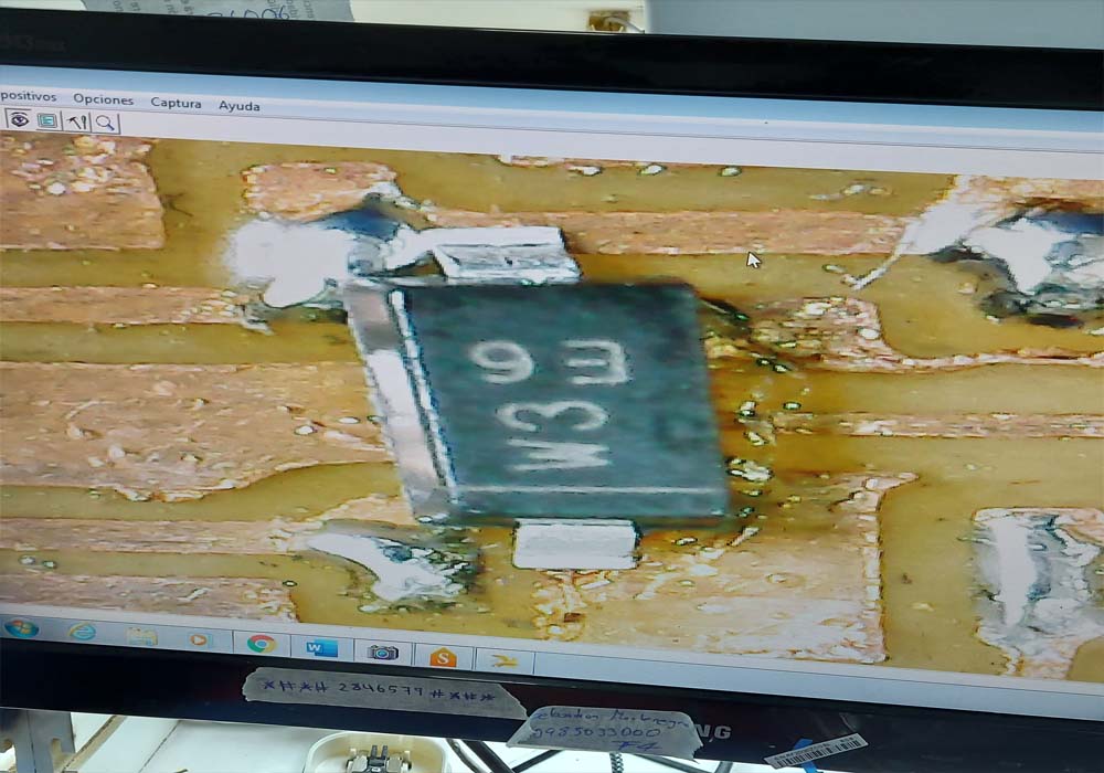
To solder the electronic components, it was helpful to use a microscope to check the connections.
Programming the ATtiny 45 whit ISP programer
The FabTinyStar is yet another version of an AVR ISP programmer/board that can be produced in a fab lab using a milled PCB and readily available components.
The project is based on the efforts of many people. For more history of the FabTinyStar and the people who have contributed to it,
Building the FabTinyISP
please refer to Zaerc's FabTinyStar page.
To start with the programming of the programmer, ews need to download Atmel AVR Toolchain for Windows and you can do it from this link
Atmel AVR Toolchain for Windows, once
downloaded it must be installed in C: \ Program Files, then we must install GNU Make and we can find it in the following link
Gnu Make . Its installation
is very easy, we simply accept the default values.
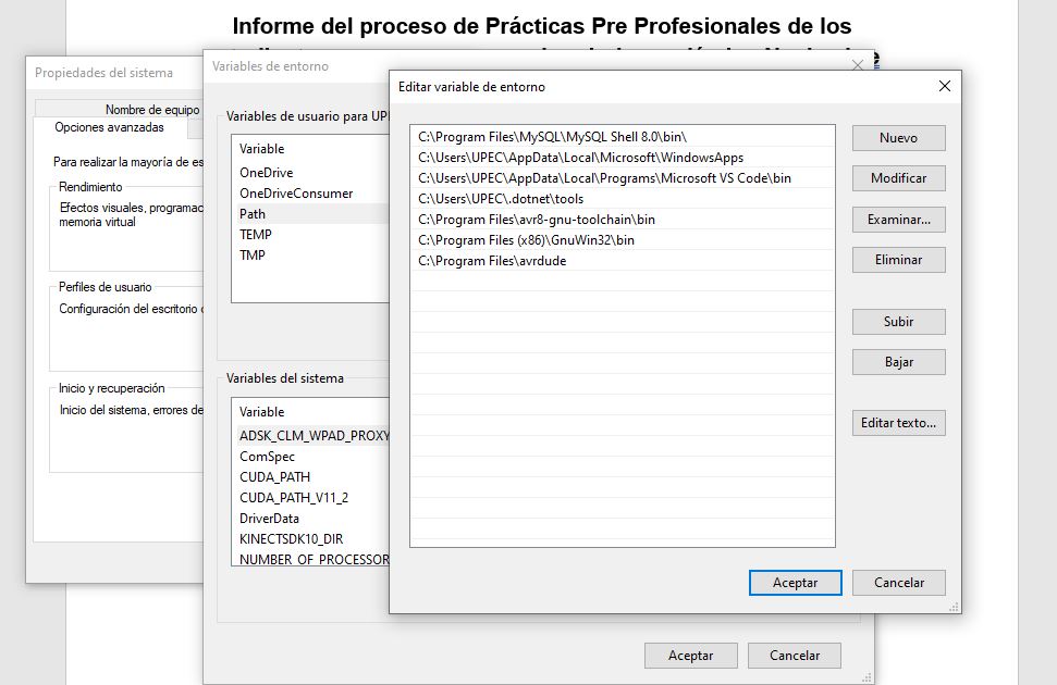
Now we will install avrdude, we can download it from the following link avrdude. We will place this folder at the following address C: \ Program Files.
And finally we will update the Path, as shown in the following images
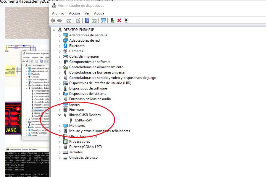
It may happen that our programmer is not recognized, for this we must install the respective driver and we can verify it on the system devices
We cannot support with the zadig program and you can download it from the following link zadig.exe
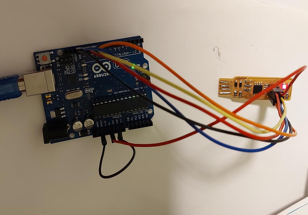
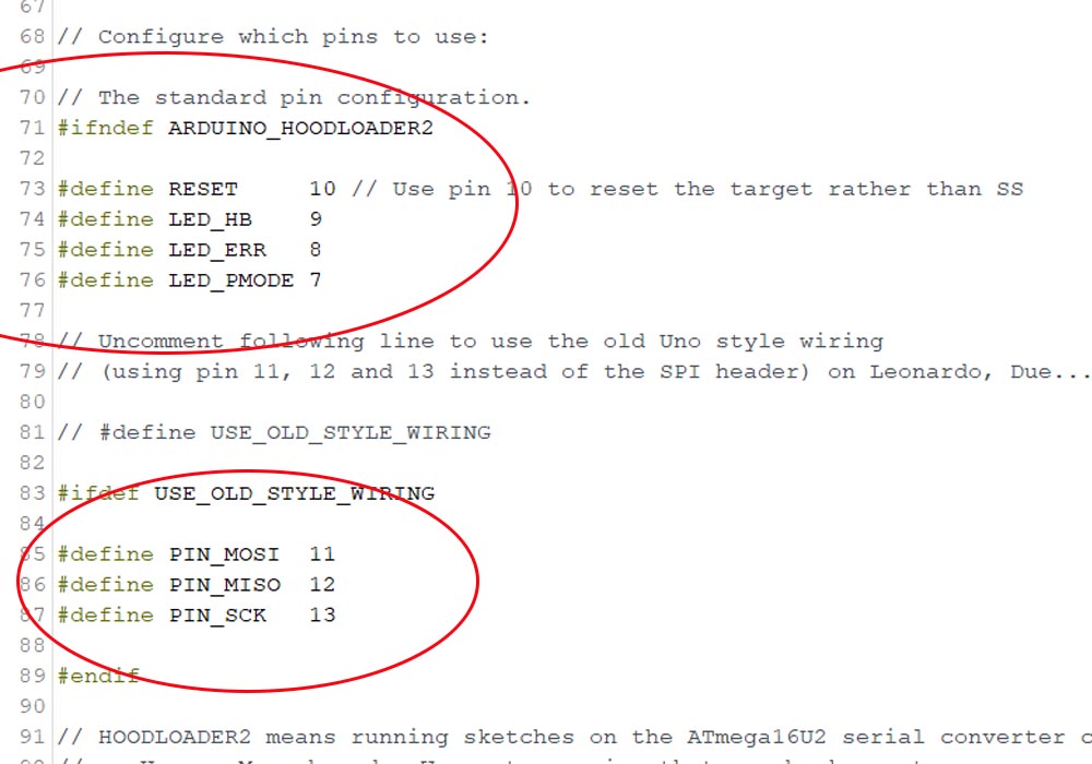
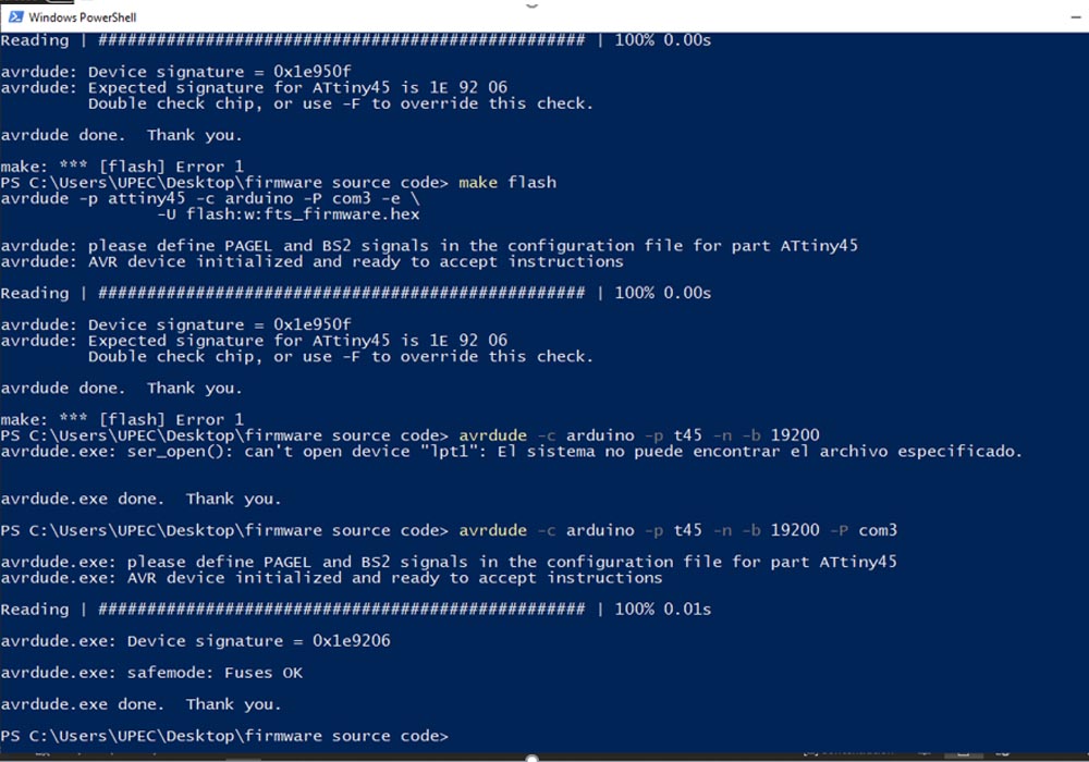
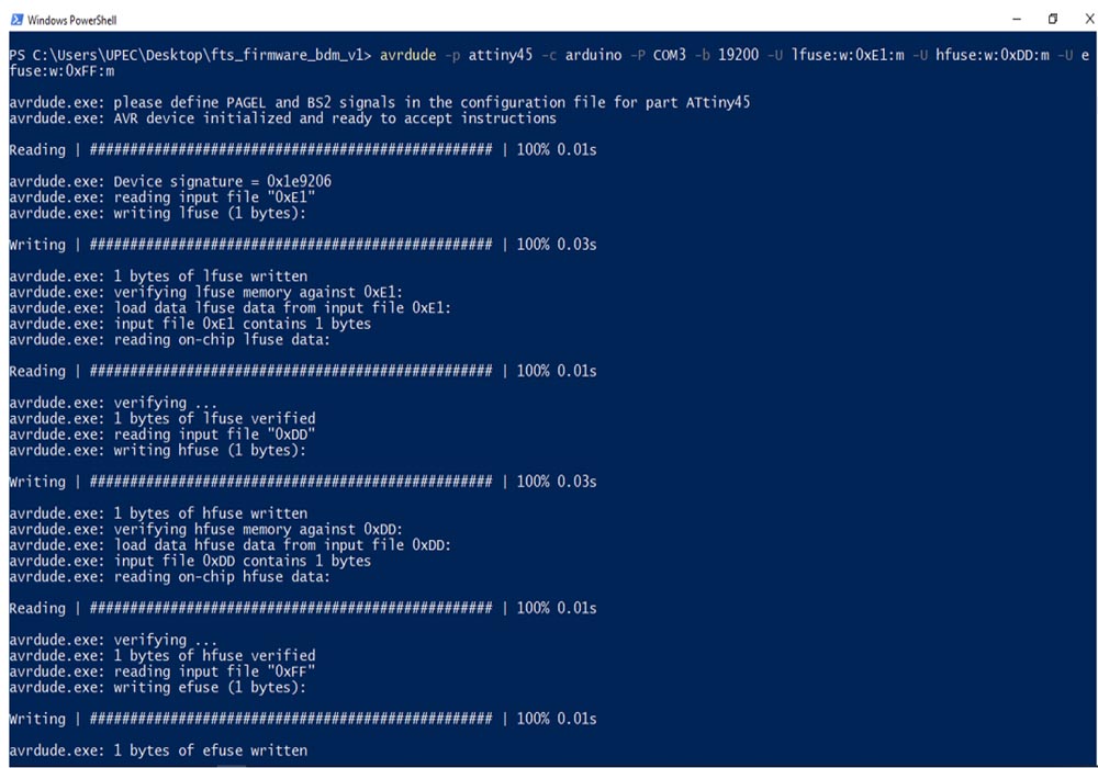
Identifying the pins is very important, on this will depend the success when burning the fuses of our Attiny 45
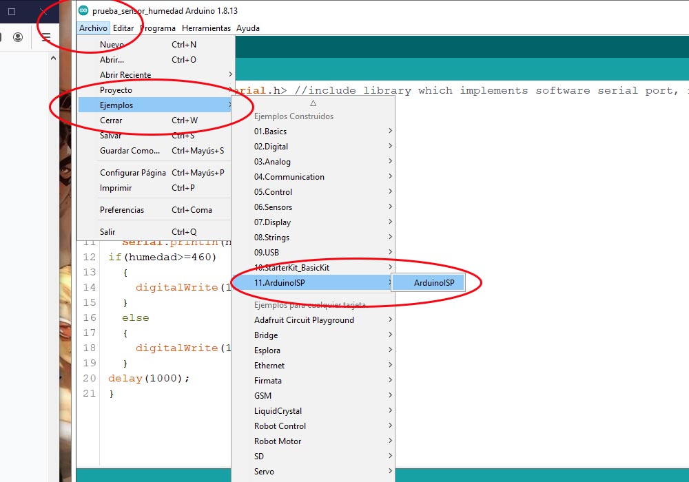
to start with the programming we will use an arduino uno, which we will use as a programmer
finished this, we will open a terminal and execute the following command -c arduino -b 19200 -p t45 -P COM3
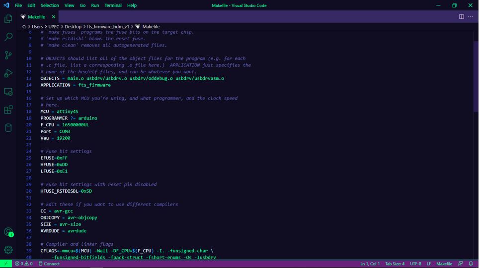
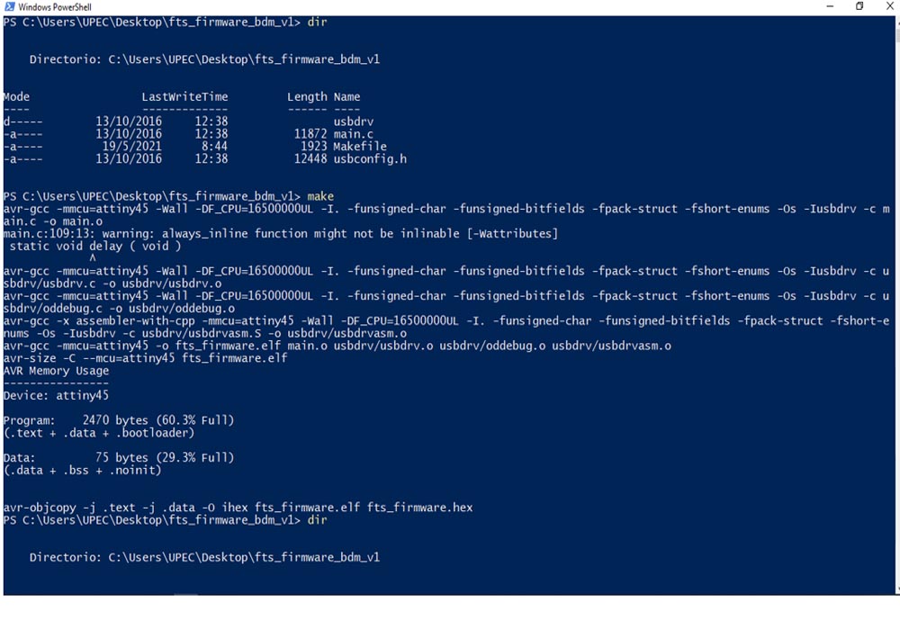
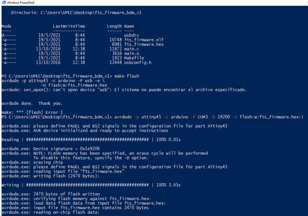
It is very important to properly configure the makefile file, correctly add the port, the baud rate, and the location of the files to be able to execute the make clean,
make flash, avrdude commands according to the indications of the links provided above.
General Conclusion:
The manufacturing process of the circuit board was very interesting to learn how to use the different parameters that we can use in the Mods and how they affe
result. In the same way, learning to program and burn the programmer's fuses was fun, although stressful, due to the possibility of blocking the board if it
is done in a bad way.
It took me a bit to understand the operation of the cnc as well as its calibration, the first PCB came out smaller due to a bad calibration, in that process
added the zero point, I broke several millings that came with the machine, it only saved one, now I understand the G code much better to the point of editing
it manually, I had not considered the width of the tip and the angle of the V, for the moment of cutting the plate I used my annotations from several weeks
ago to configure the MODS, now I understand the need for a calibrator and take these measurements into account
