CHECK LIST
Group assignment
- Characterize the design rules for your PCB production process: document feeds, speeds, plunge rate, depth of cut (traces and outline) and tooling.
- Document your work (in a group or individually)
MODS
To prepare the files for milling we used mods. Here you can find the parameters we used for the traces and for cutting.
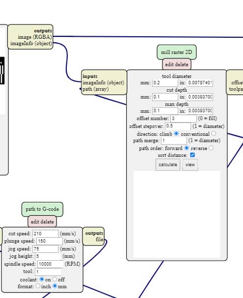 Parameters used for traces
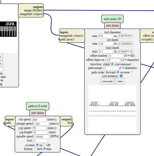 Parameters used for cutting
AUTOLEVELER
The auto leveler, leveling instrument, or automatic level is an optical instrument used to establish or verify points in the same horizontal plane. It is used in surveying and building with a vertical staff to measure height differences and to transfer, measure and set heights.
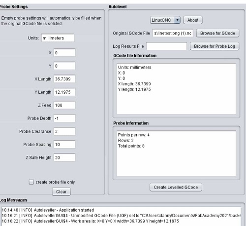 Parameters used for traces
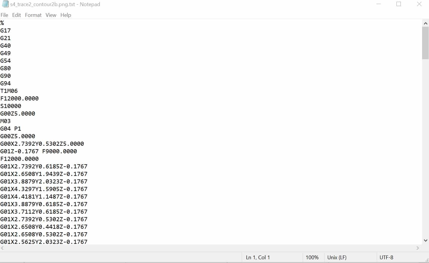
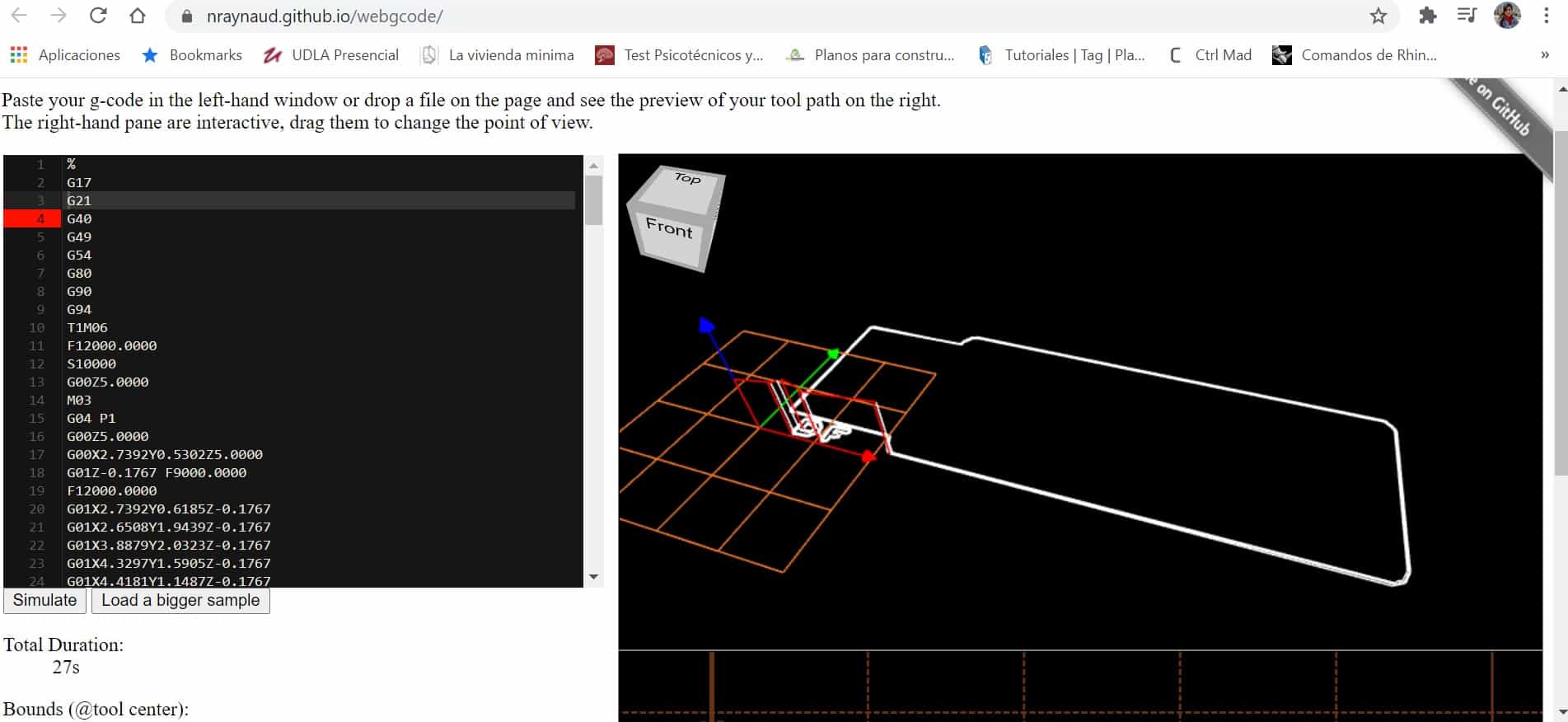
G-CODE SIMULATOR
A G-Code simulator is a type of software tool that provides a virtual representation of a CNC machine's tool path made by following the instructions in a G-Code file. They range from simple simulators that output a single image of the tool path to complex tools that can detect collisions and plot the path in 3D.
MACHINE AND TOOLS USED
For this week assignment the small milling machine was having some troubles, so we used the CNC 1325 which is also very accurate.
WORKFLOW TO MILL A CIRCUIT BOARD
- Prepare the machine, load any underlay and the raw PCB board, paste it with double side tape, as flat as possible.
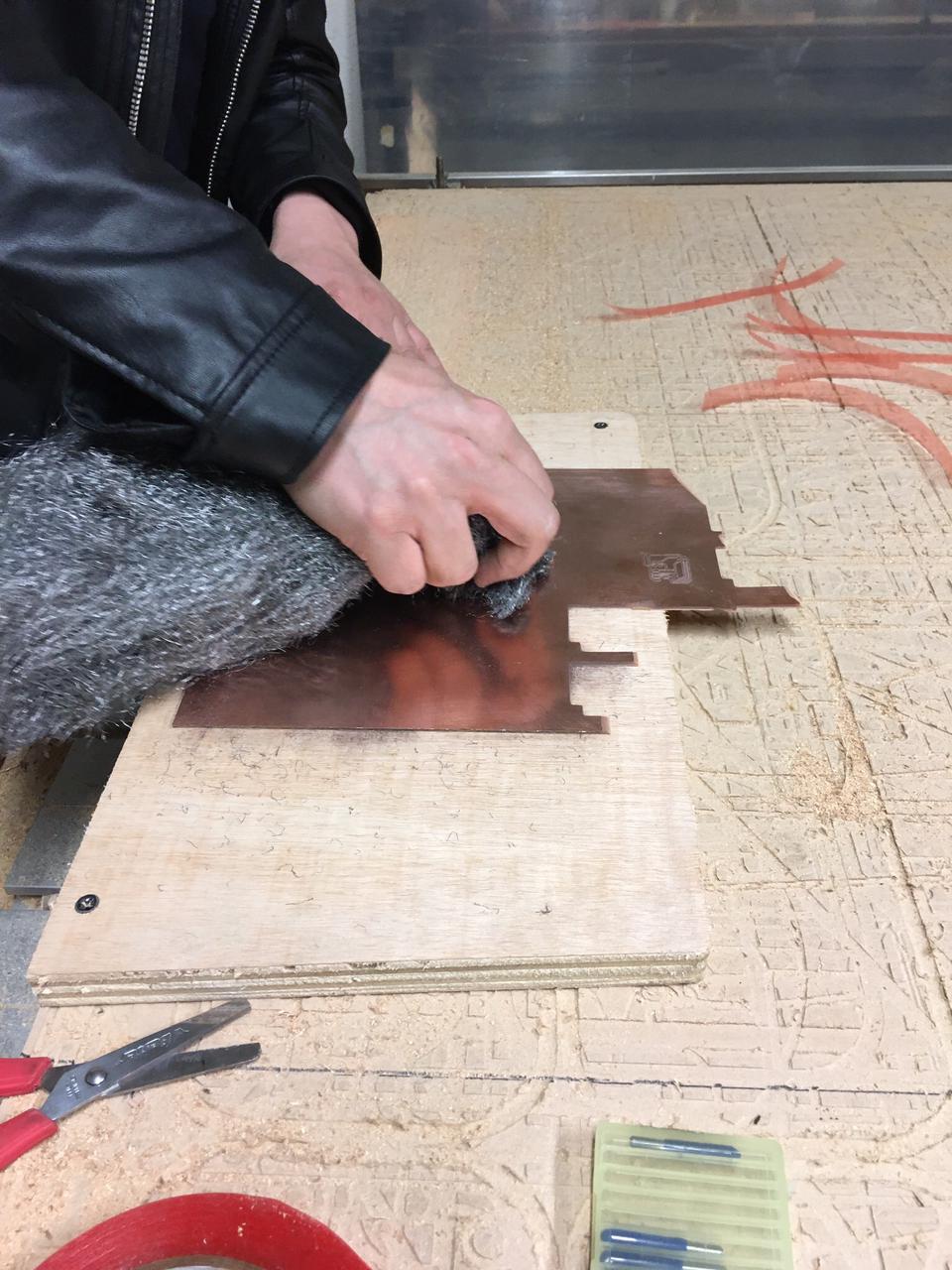
- Ensure that the surface is clean and conductive. If needed use thin steel wool to remove coats and oxide layers from the cooper. Also, use alcohol to clean any grace from your fingers or the environment.
- Install the milling bit, and zero the xy axis, put auto-level sensor, use that to zero the z axis by lowering the z of the machine by small steps.
- Run the auto level program (in this case some of the first steps of the G-code, depends on the machine), remove the sensor and then start the milling process.
- Cut your traces G-code first, then change the mill bit if needed, run the cut-out program to separate your circuit board
- At the end remove any exes material and leave the CNC bed clean.
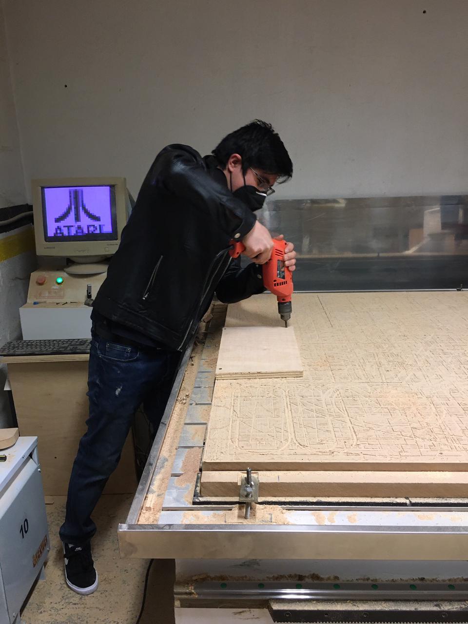
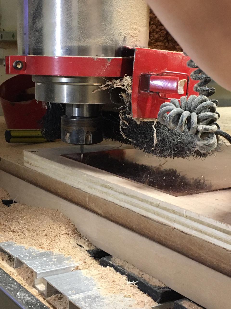
Images on the CNC for engravig and cutting the board.
RESULTS
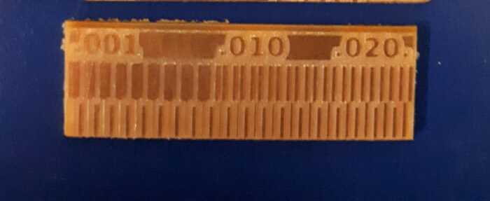
To characterize the CNC capabilities and how to apply that to the circuit board design we mill this line-test provided by Neil, on the Electronics Production class.
So after the milling process we can see on the test, that the minimum space between traces is a little bit smaller than 0.010 inch or 0.25mm and the minimum possible width of a trace is between 0.001 inch and 0.010 inch, about 0.127mm wide.