Computer-Controlled Cutting

Group assignment:

  • characterize your lasercutter's focus, power, speed, rate, kerf, joint clearance and types
  • Individual assignment:

  • Cut something on the vinylcutter
  • Design, lasercut, and document a parametric construction kit, accounting for the lasercutter kerf, which can be assembled in multiple ways,
  • For extra credit include elements that aren't flat.
  • Introduction to Computer-Controlled Cutting:

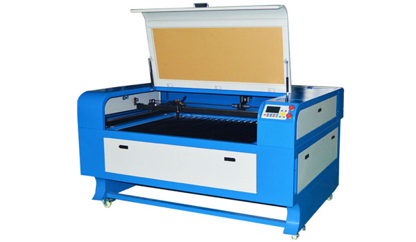
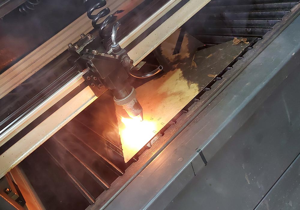
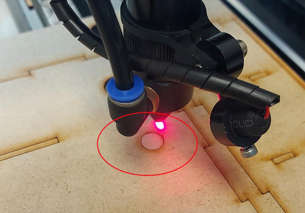
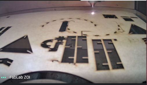
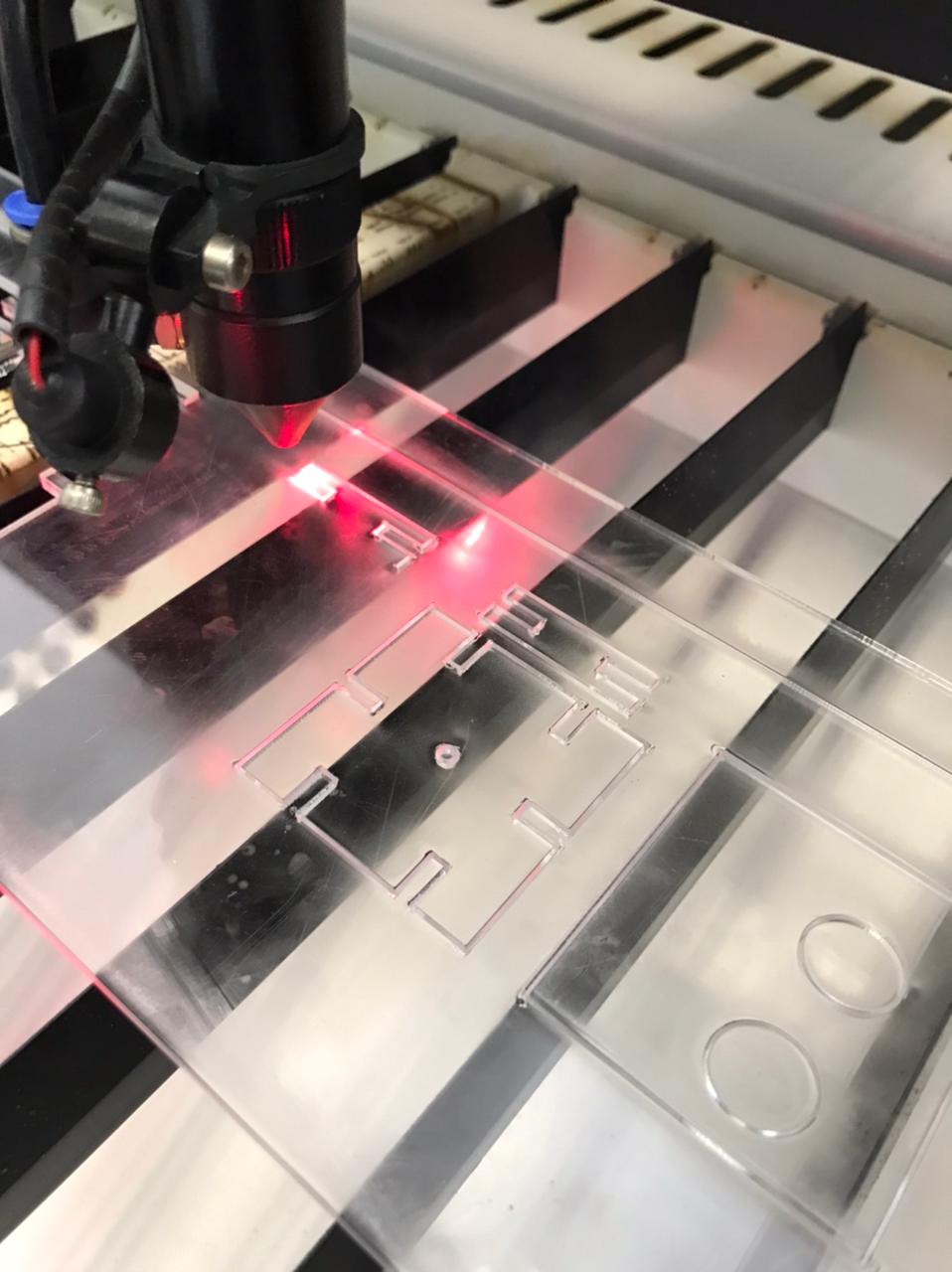
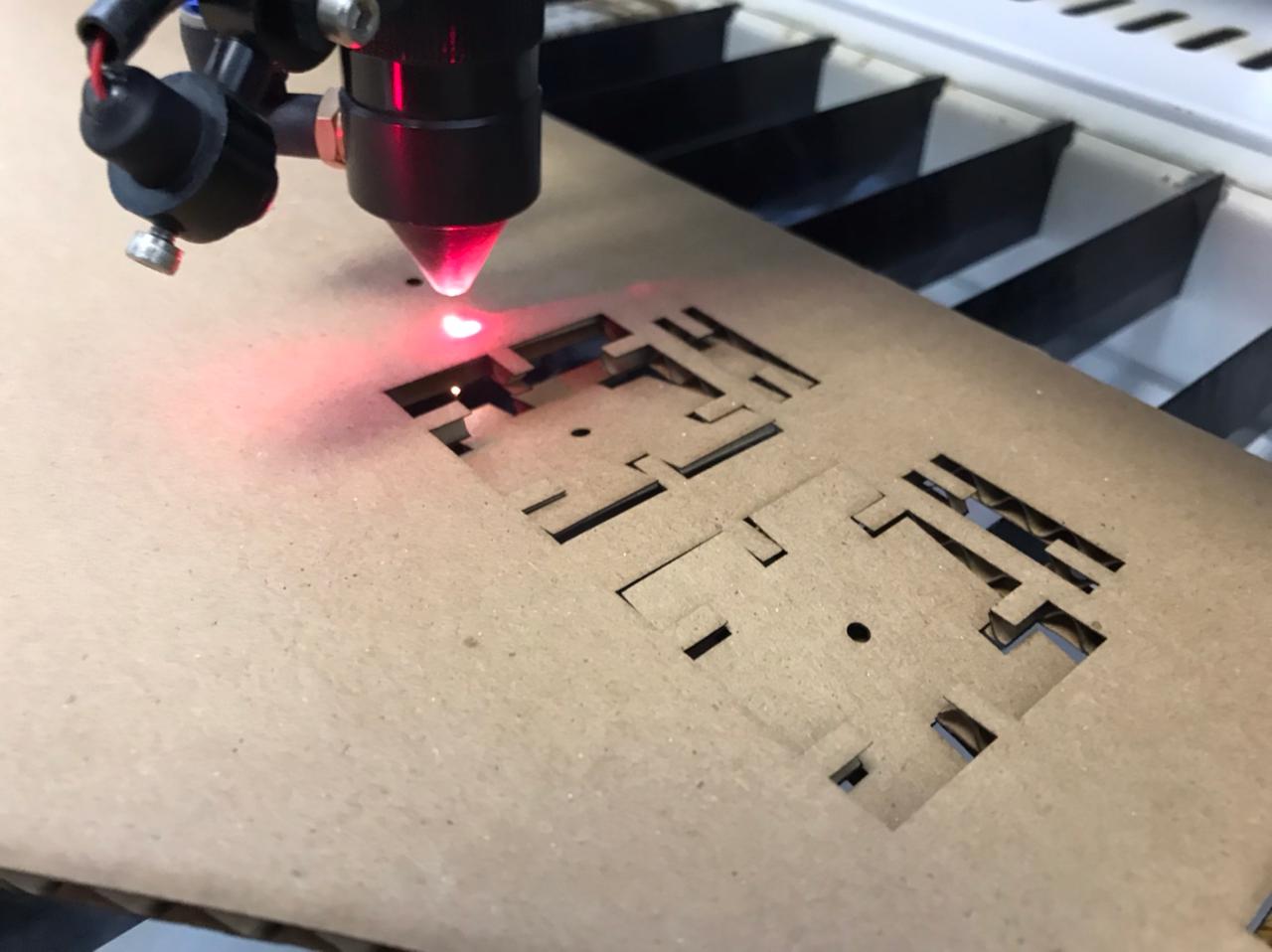
    Laser cutting works by focusing the power of a high-power laser onto the surface of the material to be cut. The energy in the laser beam is absorbed into the surface of material, and the energy of the laser is converted into heat, which melts or vaporizes the material.
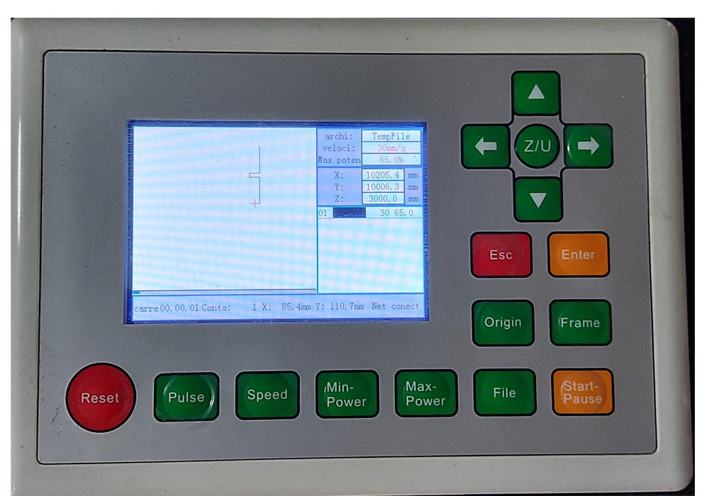
    Laser cutting is mainly a thermal process in which a focused laser beam is used to melt material in a localised area. A co-axial gas jet is used to eject the molten material and create a kerf. A continuous cut is produced by moving the laser beam or workpiece under CNC control.
    The following video explain how laser works.

    Parametric Design.


    Parametric design is a process based on algorithmic thinking that enables the expression of parameters and rules that, together, define, encode and clarify the relationship between design intent and design response.
    It’s hard to define in just a few words, and googling “parametric design” or “computational design” leads to some dry explanations that can sound a little too abstract. For example, Wikipedia says it’s “a paradigm in design where the relationship between elements is used to manipulate and inform the design of complex geometries and structures.” This is accurate but not that straightforward, and leaves most of us scratching our heads.

    Starting the design.


    freeCad.


    For this task I use freecad, which seems to me to have the necessary tools to carry out the parametric design of the part that I will design


    To start with the design, I drew the basic shape of the piece, in this way we will place the restrictions on the general geometry


    Then I continue to place the constraints on the different segments that shape the puzzle.


    In the drop-down we can find the different work areas, this will display the different drawing options and design tools, we can also find in the toolbar in the Sketch button, here we will find all the sketch geometries, sketch restrictions and tools sketch


    Finally I created the Spreadsheed file in which the final restrictions are defined, these restrictions will parameterize our puzzle, in this file I defined the size of the piece as well as the thickness of the material to be cut by the laser cutter.


    Parameterizing the model


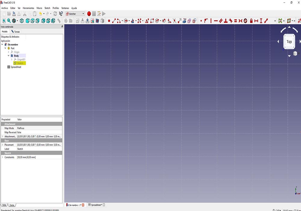
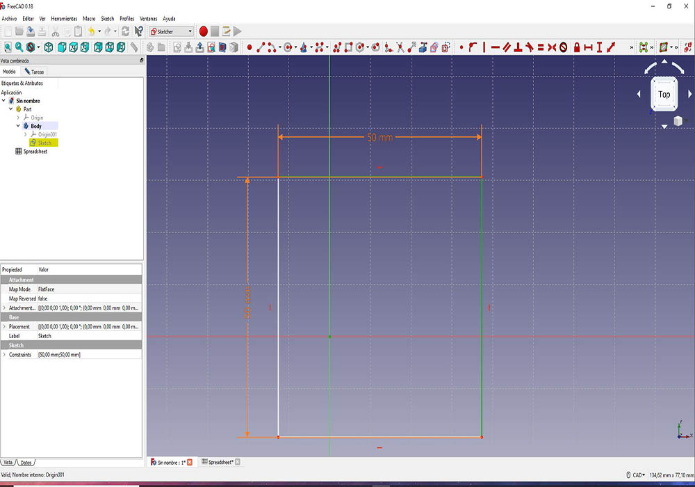
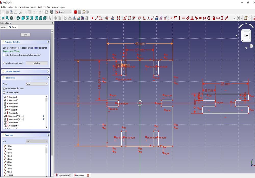
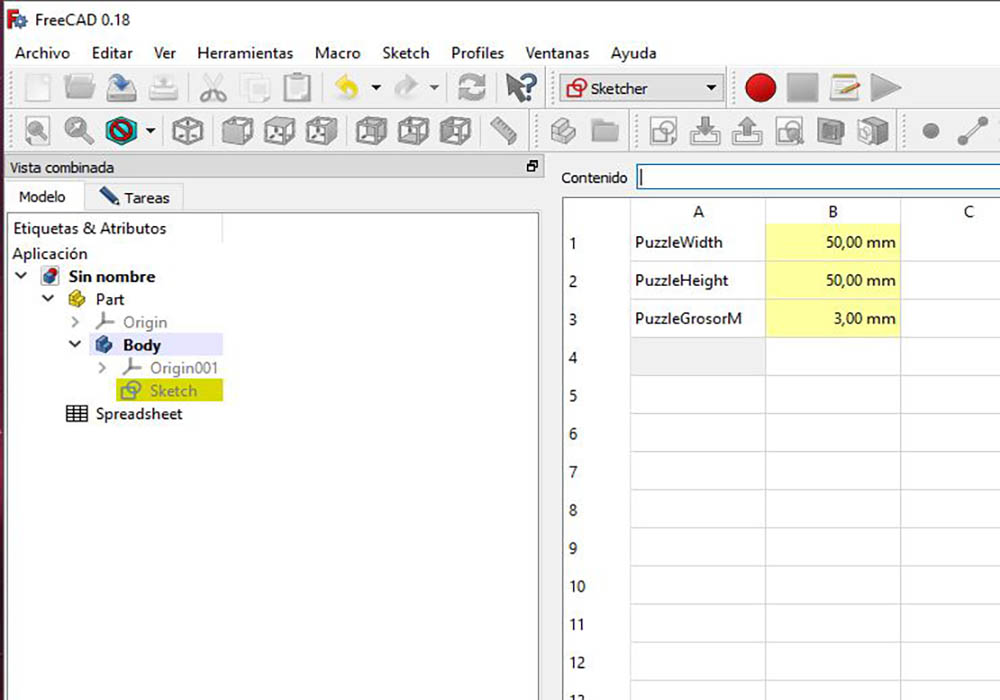
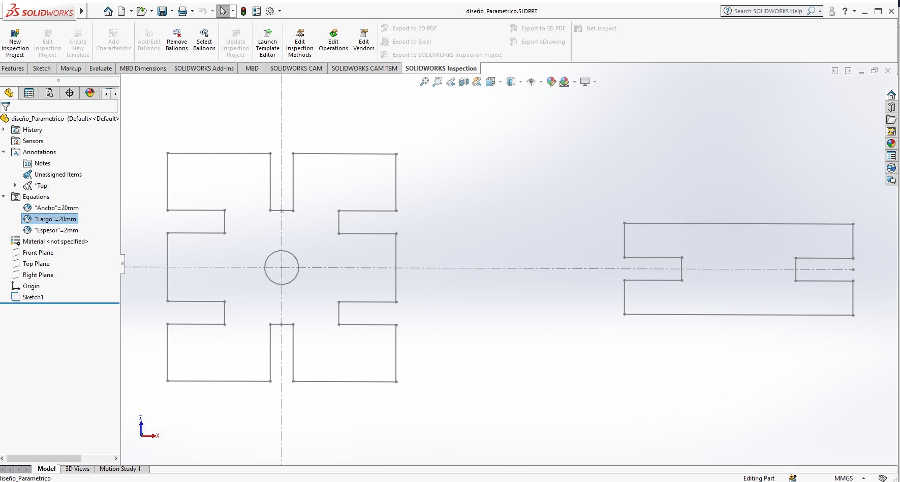
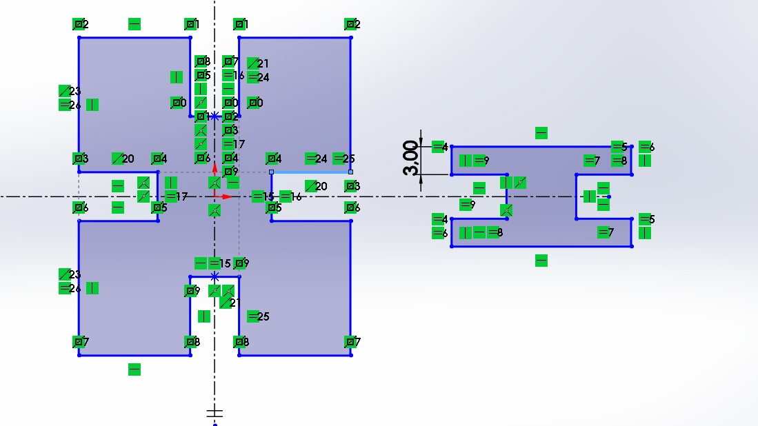
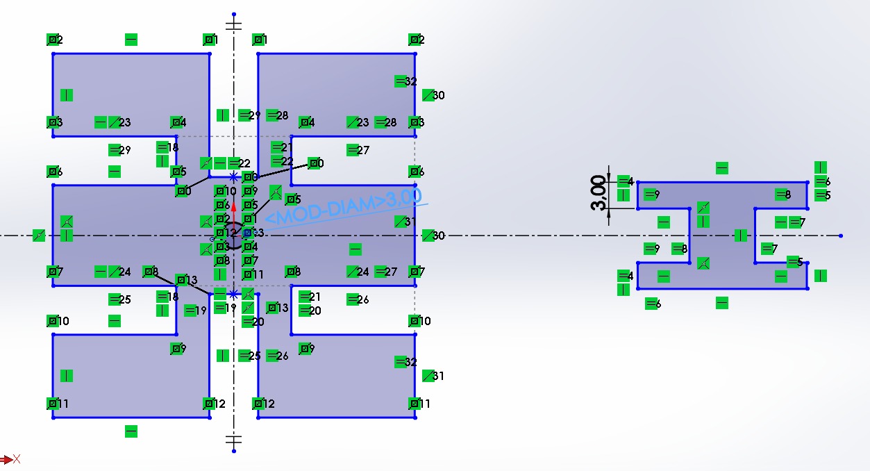
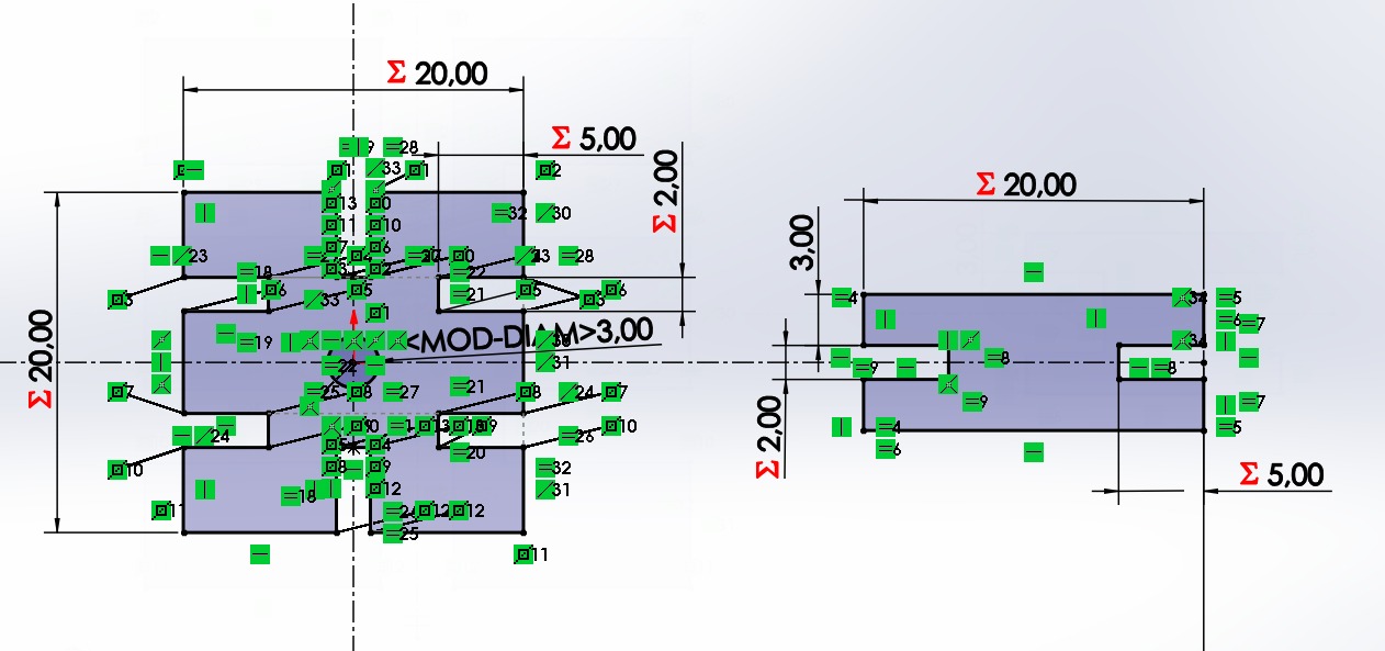
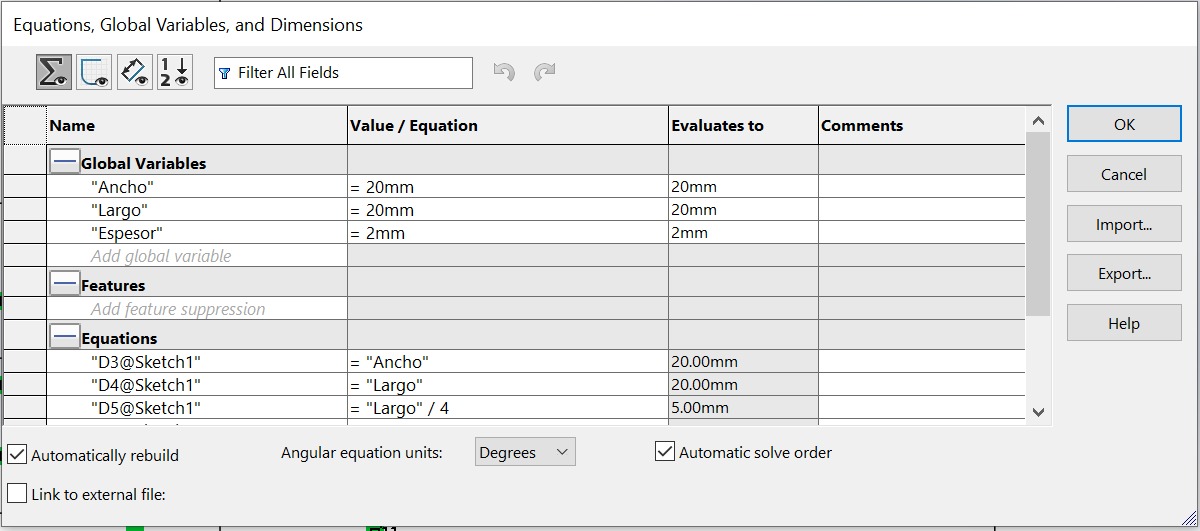
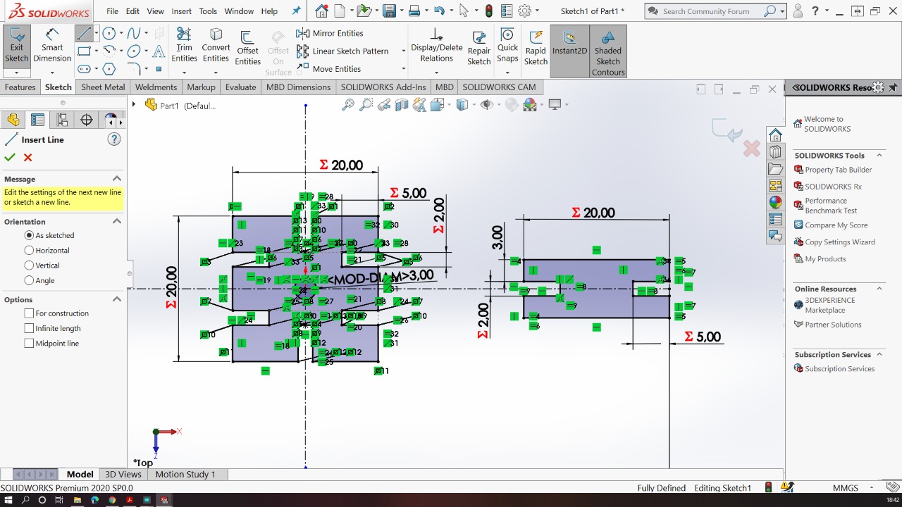
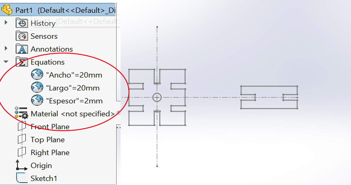
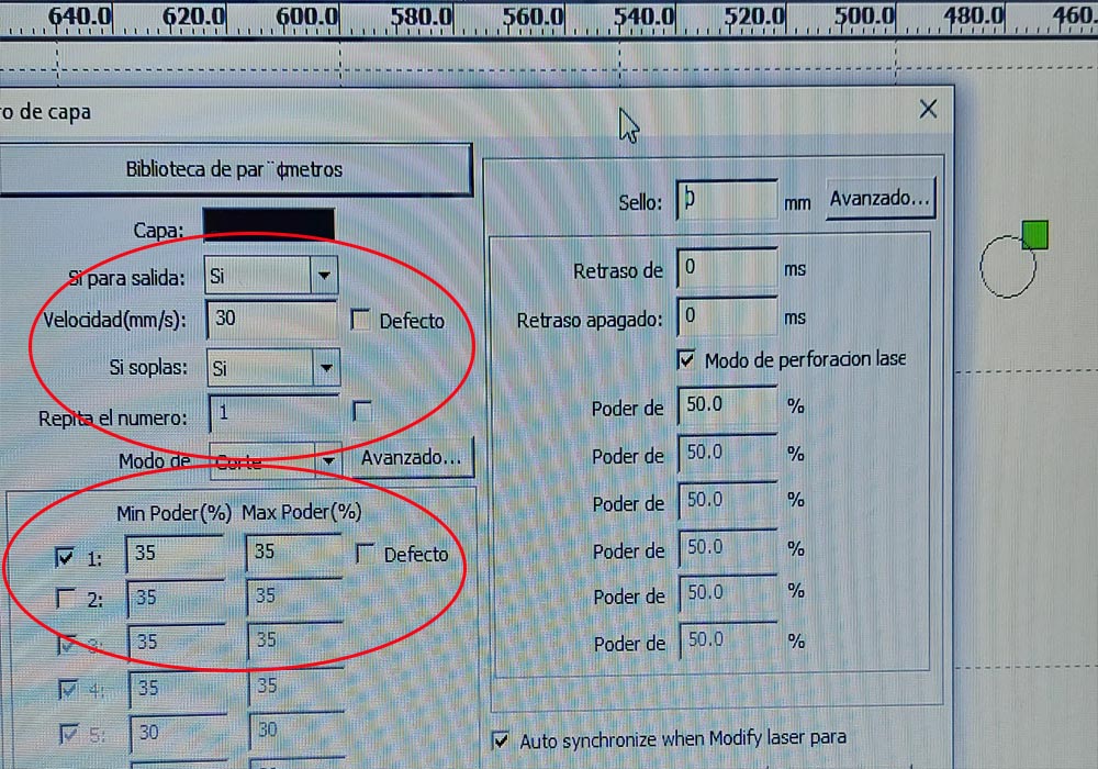
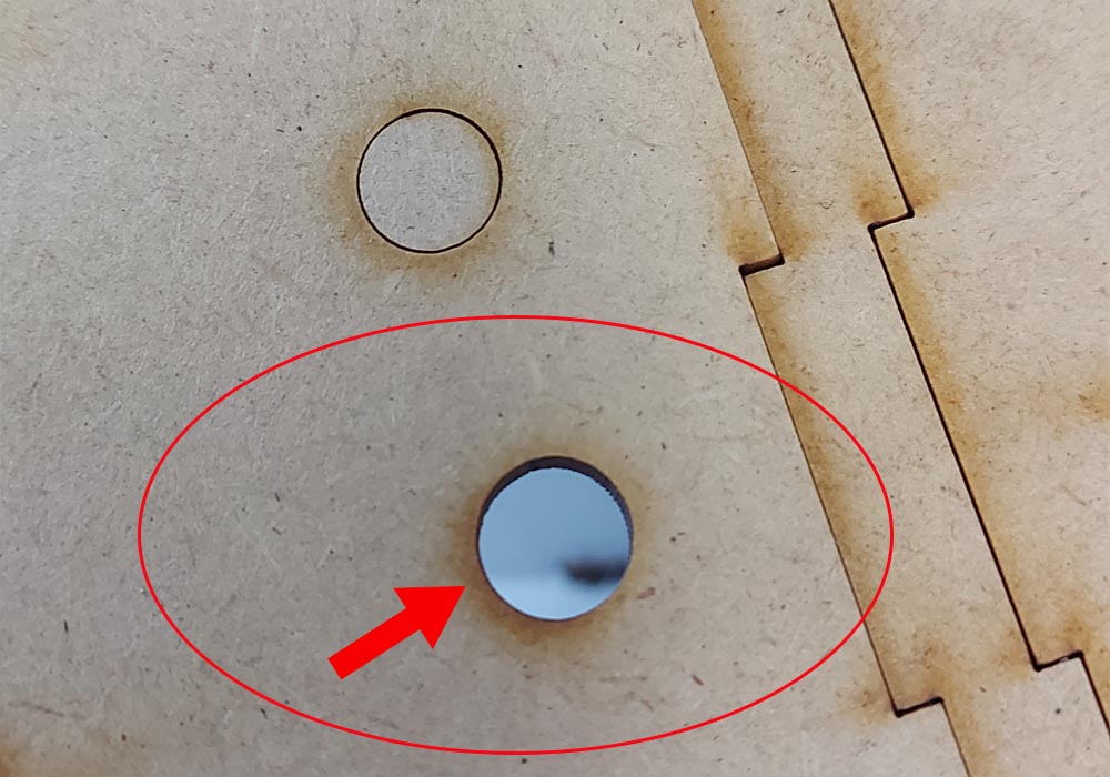
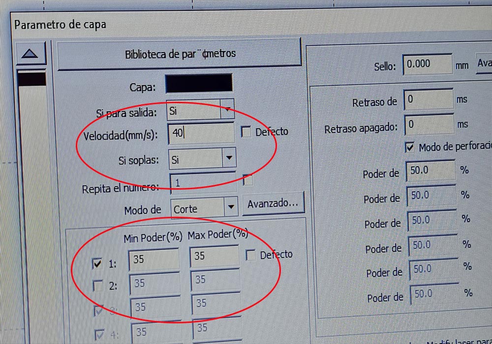
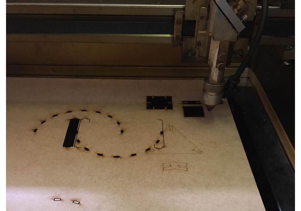
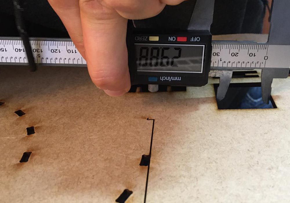
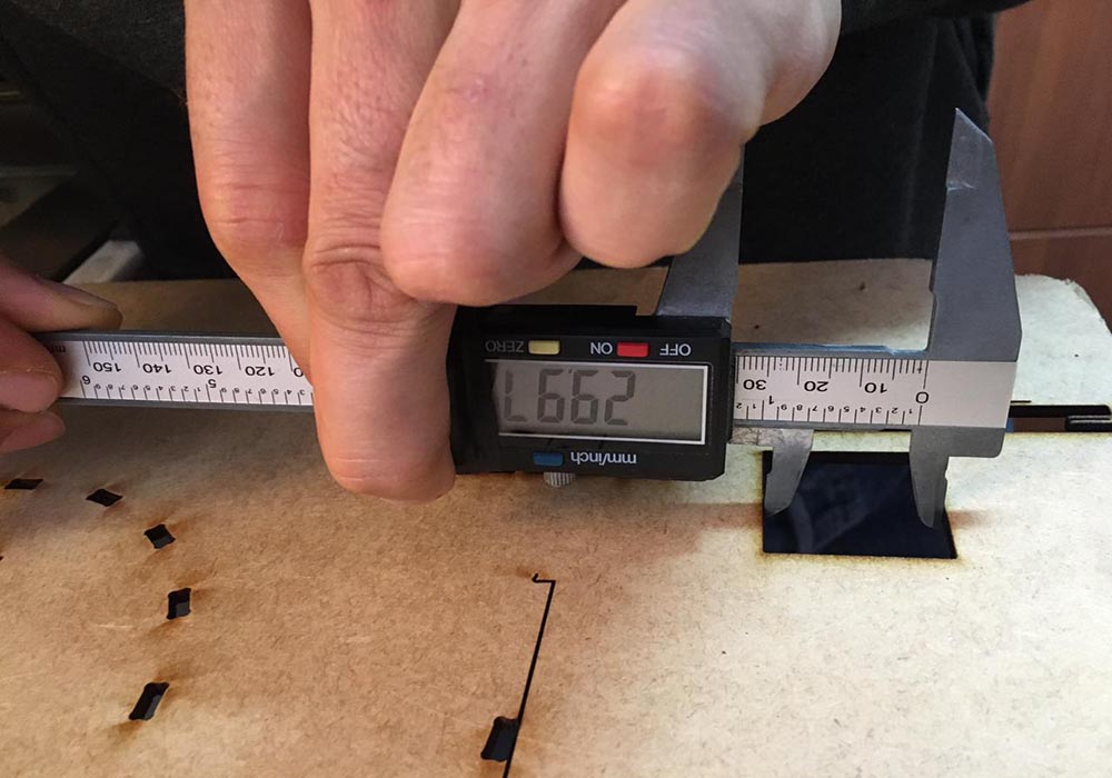
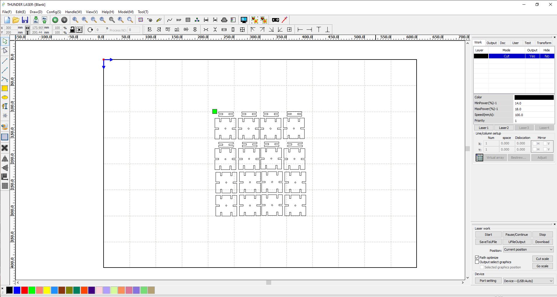
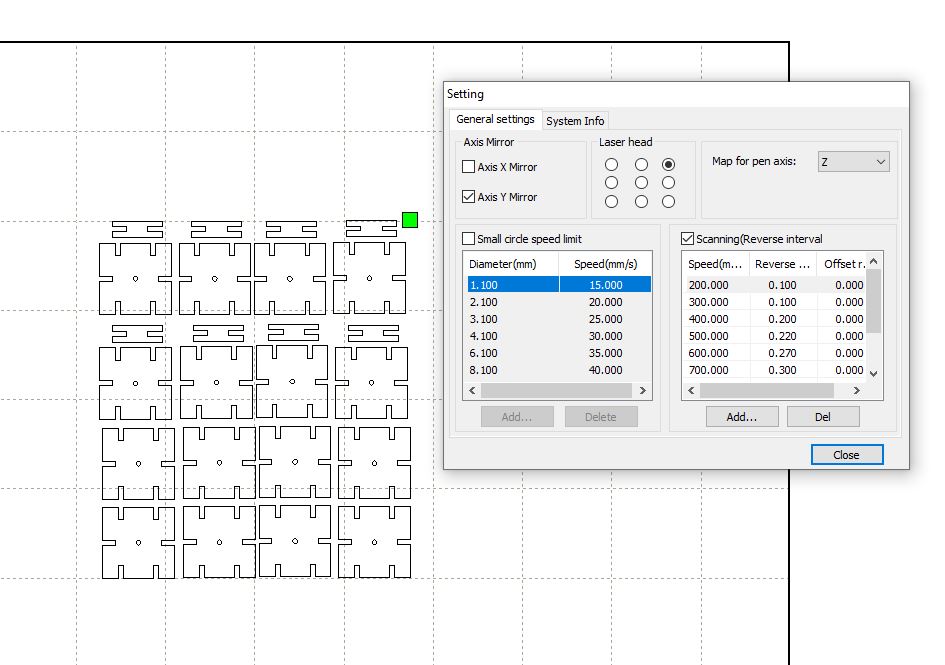
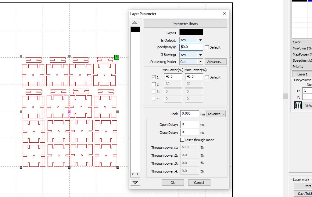
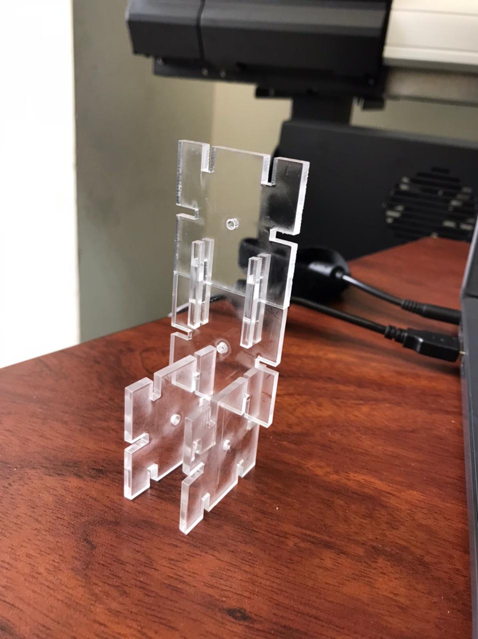
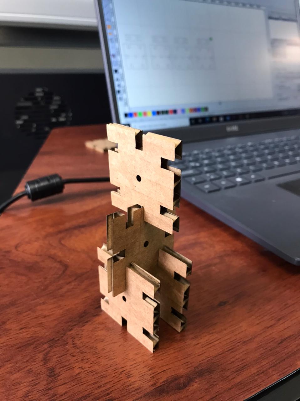
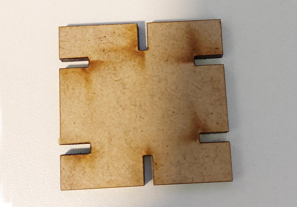
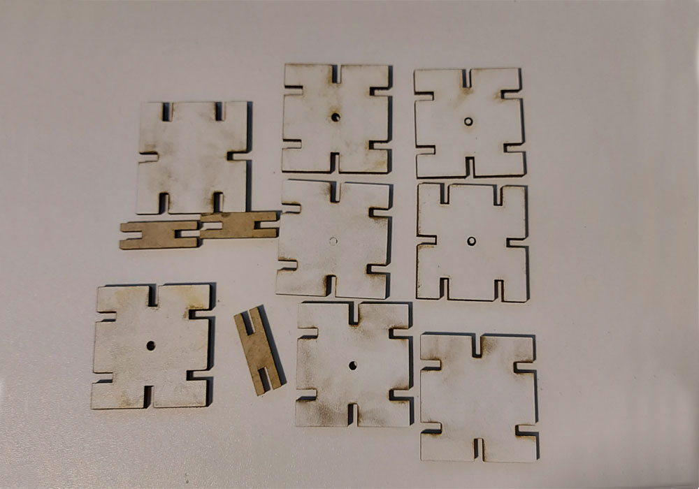
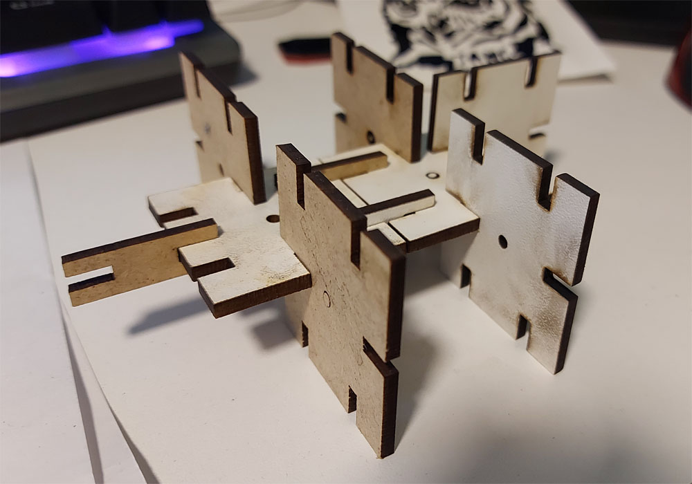
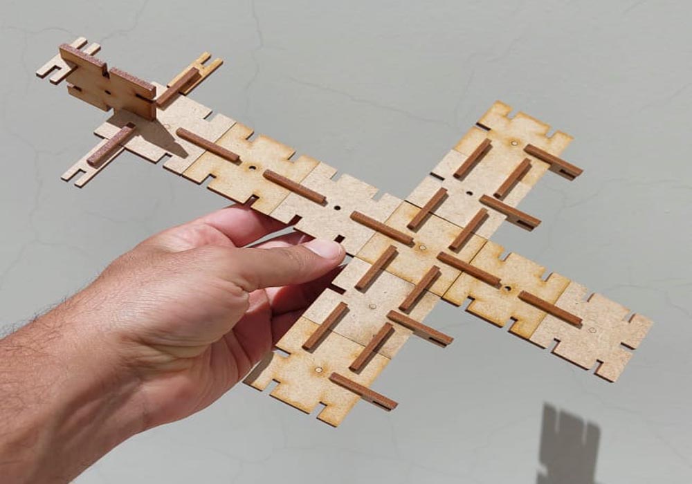
    The design of the puzzle piece was parameterized, the thickness of the material was chosen to be able to change and calculate the kerf of the piece at the time of cutting, For this I use the Spreadsheed which is an excel file that allows us to create variables, assign them a unit of measure and an alias, in order to place the restrictions


    Finally the file is exported to DXF to be able to be opened with the laser cutter program, in my case it is RDWorks


    Problems found


    Initially because of my little experience in handling design programs, I am inclined to think that FreeCad, due to its easy interface and intuitive tools, was the right choice for parametric design. But in my first attempt I made several mistakes, the first one did not place all the shape restrictions, this causes that when the size of the piece varies it is deformed, You can verify it by downloading the file and changing the size of the part in the SpreatSheet. Second, I include two pieces in the same design, this makes it even more difficult to control the restrictions, and finally in the end you have so many restrictions that it is a real headache to understand what is happening with the design, As a recommendation, use different sketches


    Solid works


    Now with a little more experience, really not much .... lol, after several weeks and with the arrival of the laser cutting machine to the laboratory I have been able to carry out more tests, and try other programs such as solid works


    To start with the design, I drew the basic shape of the piece, in this way we will place the restrictions on the general geometry


    Then I continue to place the constraints on the different segments that shape the puzzle.


    Finally I created the Spreadsheed file something similar to freeCad, Solid Works can define variables these are created in the equations folder, in which the final restrictions are defined, these restrictions will parameterize our puzzle, in this file I defined the size of the piece as well as the thickness of the material to be cut by the laser cutter.


    Conclusion


    Although freeCad is quite intuitive, there are other tools. that although they seem more difficult to learn at first. They will allow us to have a better control of our designs, these tools can be Rhino + GrassShoper or SolidWorkss


    Settings the laser cutting:


    Cutting tests, powers and speeds in a 100w power laser cutter, we will try some parameters to find the most optimal ones to cut a 3mm mdf in our laser cutter


    first attempt unsuccessful, don't cut the hole


    second attempt was successful, but there is a burn around the hole


    third attempt was successful, they would be the most suitable parameters for our laser cutter and 3mm mdf


    fourth attempt did not cut the hole, without success


    The Kerf:


    Kerf is defined as the width of material that is removed by a cutting process. It was originally used to describe how much wood was removed by a saw, because the teeth on a saw are bent to the side, so that they remove more material than the width of the saw blade itself, preventing the blade from getting stuck in the wood. Kerf width is a measure of how much material is removed.When talking about CNC shape cutting with typical cutting processes, kerf is the width of material that the process removes as it cuts through the plate. Over the years I’ve heard some people use the term when referring to the angle on the edge of the part, but that would be an incorrect use of the word. The “cut angle” on the edge of the part makes measuring the kerf width sorta tricky, but for consistency, the word “kerf” should only be used when talking about the actual cut width. know more about kerf


    parallax error when taking the measurement


    Controlling the laser cutting machine


    The software used to control the laser cutter is RDWorks, this program allows us to configure the cutting parameters, for this assignment this week we will make a very simple puzzle made in 3mm mdf, but the end result was very interesting, everything that can be assembled with a piece as simple as the one manufactured is incredible.


    A program was sought to help with the location of the pieces for the cuts to help minimize the waste of material, but most are paid, and one that is found, serves to make straight cuts by introducing the measurements of the cuts, for what I organize the pieces to cut manually


    The video also shows that the vectors of the piece being cut are not continuous and that the machine performs two passes. This can be improved with the 'combine curve' tool that is in the 'handle' drop-down of rdworks. and you can see the improvement in the following video


    These are the results in different materials cut with the laser cutter, 4mm cardboard, 3mm acrylic, for acrylic cutting the


    cutting power used in the mdf was varied by 10%, this so that the pieces fit better.


    Parametric construction kit:


    Settings the laser cutting:


    Final result:


    Vinyl cut


    The first thing was to start from a simple design that allows more pieces to fit together to form larger structures.

    For the vinyl cutting job I downloaded an image of an owl, this image I vectorized with adobe illustrator, using the image tracing option

    First steps:


    The machine configuration:

  • Owl design and cut.

  • Before starting with the vinyl cutting, a calibration file was sent to obtain the appropriate parameters according to the material used


    Once the vinyl cutter is calibrated, we are going to use an image of an owl that was previously vectorized with adobe illustrator, to make the adhesive use the SignMaster CUT + ARMS software


    To transfer our adhesive I use a transfer which helps us transfer our work especially when it has a very intricate design


    The final result


    vectors in adove illustrator Owl_1 vinyl cut

    vectors in adove illustrator Owl_2 vinyl cut

    General Conclusion:

    This week's work was quite interesting and opened the doors to new ideas and design possibilities that I had not explored before, there is a lot to learn in design tools, but expertise is not learned overnight.

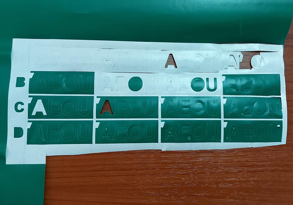
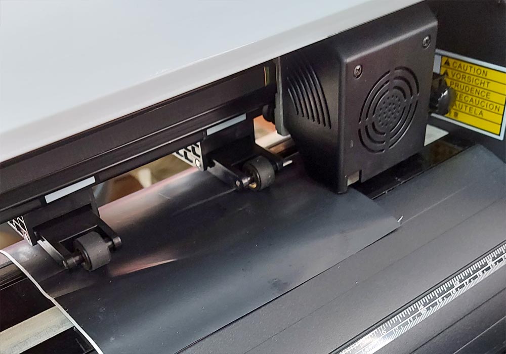
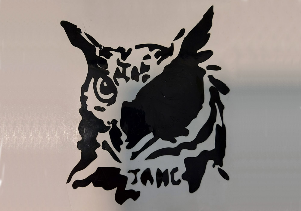
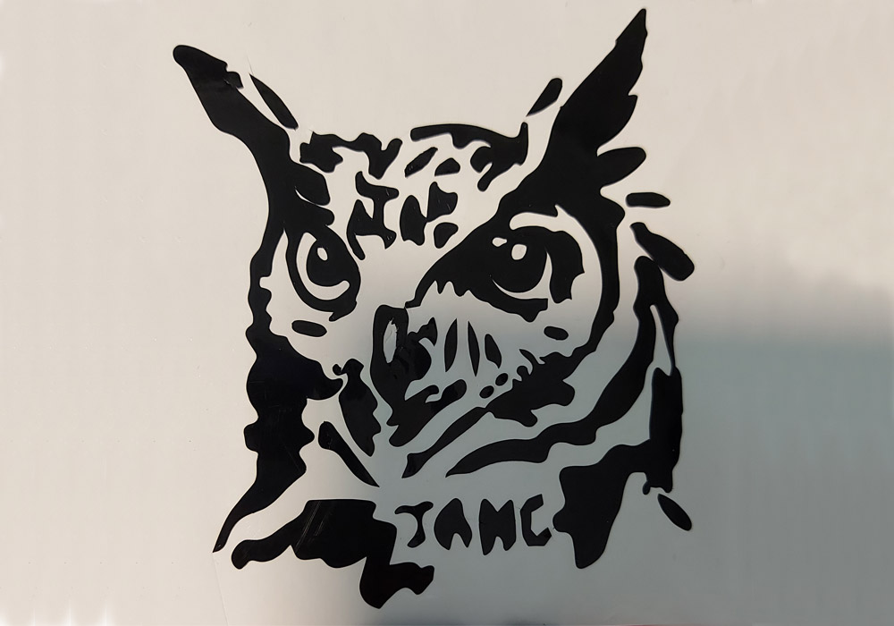
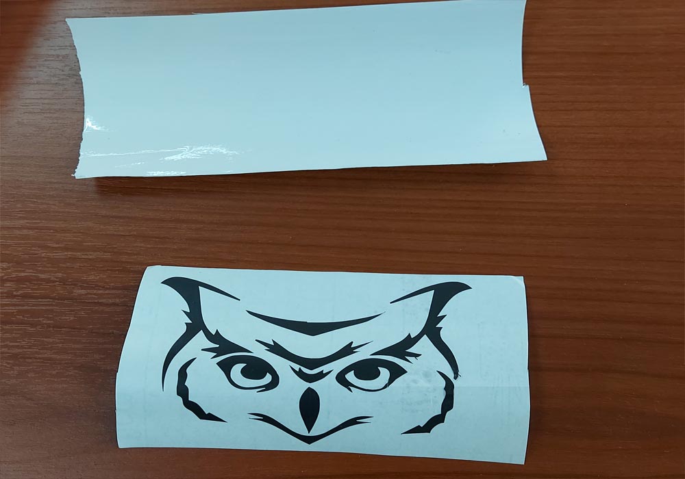
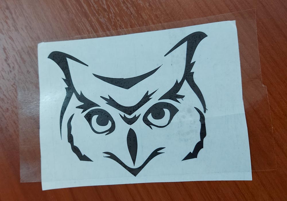
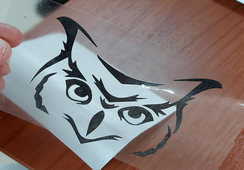
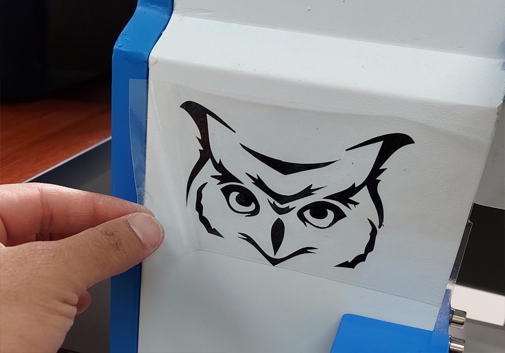
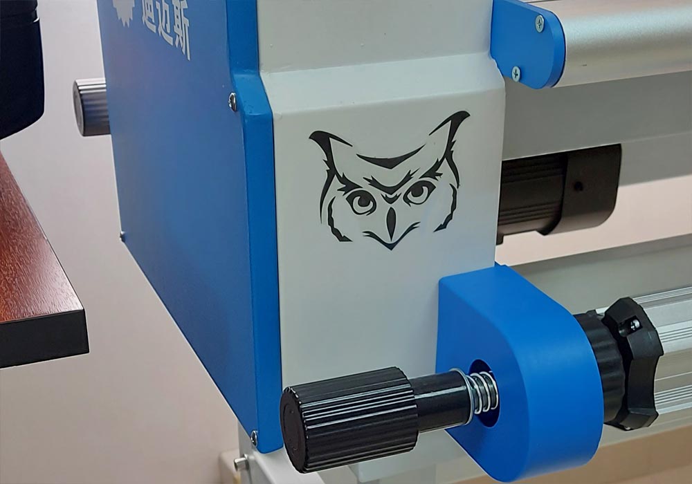
    Finally, you have to remember all the safety parameters to make good use of the machines, especially the laser cutter, which can be very dangerous. When it comes to cutting vinyl, it was a lot of fun to be able to make custom stickers, although the job of removing excess material is a bit stressful