CHECK LIST
Group assignment
- Characterize your lasercutter's focus, power, speed, rate, kerf, and joint clearance.
The Fab Lab is an industrial environment where are machines and processes happening. This circumstances can be dangerous if people have no knowledge of security rules. Everyone in a Fab Lab have to know some basics things about security to prevent injuries.
Security Rules in Fab Lab
- Excess of confindence can cause an accident, follow the workflow and the rules below.
- Ask a supervisor for help any time you fell you need it before start working.
- Ask for a supervisor assistance everytime you will use a new machine.
- Do not wear loose fitting clothing.
- If you have long hair be sure it is pulled back away from equipment and dont't loose.
- Wear safety glasses when working with any lab equipment.
- Wear safety gear and protective clothing.
- Know where the fire extinguishers are located and how to use them.
- Know the hazards associated with your work.
This information have been written with the help of Fab Lab Buinho Safety Rules document.
Laser Cutting Safety Rules
- Never leave the laser cutter unattended.
- Only cut materials approved by your instructor.
- Keep the lid closed at all times, unless loading material while the laser is turned off.
- Clean up debris in the laser cutter.
- Identify the fire extinguisher and fire blanket.
Materials not suitable for laser processing
Due to their composition, some materials are not suitable for laser cutting or engraving. Its processing can generate harmful gases or dust, either for the operators or for the machine. Some of these materials are:- Leather and artificial leather with chrome (VI)
- Carbon fibers
- Polyvinyl Chloride (PVC)
- Polyvinyl Butyral (PVB)
- Polytetrafluoroethylenes (PTFE / Teflon)
- Beryllium oxide
- materials containing halogen gases (fluorine, chlorine, bromine, iodine and astate), epoxy or phenolic resins.
Materials that you can engrave and cut with a CO2 Laser
In general terms, CO2 laser engravers and cutters are specific for working on organic materials, that is, materials that are not heat conductors:
wood, paper, plastics, acrylics, laminates, leather, rubber, etc.
For this group of materials, CO2 laser machines can engrave and cut without any problem. You just have to be careful when you engrave or cut a
material that generates a lot of residue, such as methacrylate, wood or rubber. It is necessary to have a good extraction of smoke and particles and
to carry out a periodic cleaning of the laser engraver and cutter.
CO2 laser machines can also work on mineral materials such as: stone, slate, glass, marble, ceramic, mirror, etc.
Only exceptionally can they work directly on metallic materials. In the case of painted, lacquered or anodized metals, the CO2 laser
hits the color and evaporates the pigment, leaving a white mark. That is why, in this case, the marking contrast is better on dark surfaces
(red, blue, green, black ...).
Understanding kerf and joint clearance
The main difference can be found when we compare the two definitions.
Kerf
Kerf = Width
Kerf is defined as the width of material that is removed by a cutting process.
(ESAB, Web page)
Joint clearance
Joint clearance
(engineering)
The distance between mating surfaces of a joint.
(McGraw-Hill Dictionary of Scientific & Technical Terms, Web page)
On a more practical use, the joint clarence can be used to modify the behavior of the press-fit joint or other types of joints. To make the joint 'hard' need a small joint clearance, to have a 'lose' joint you use more joint clearance.
The kerf is dependent on the laser settings and material used. It is an unavoidable result of the fabrication process. You can only compensate it by offsetting the toolpath from your desired dimension by half the kerf. Some programs can do this automatically when generating the toolpath.
To calculate the kerf, cut a square and measure the hole vs the square dimensions, the difference should be two times the kerf
The final offset applied to the toolpath should be half the calculated kerf + half your desired joint clearance if any.
Our experience with the laser cutter
Before cutting the pieces, as a group assigment we had to set the parameters on the lasser cutter:
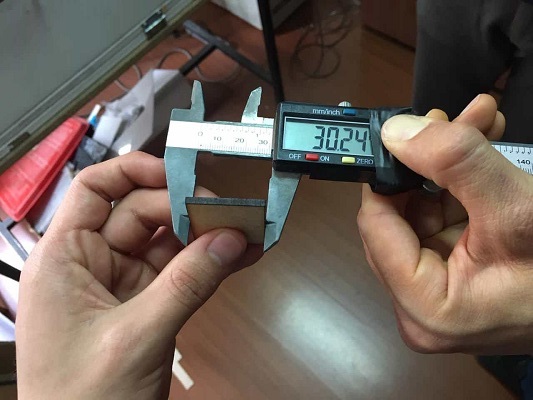
- We started measuring the material, for this exercise was a 3mm mdf
- Drew a square and cut it
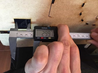
- Measure the piece and the empty space to know the difference between both
- This gave us an idea of the kerf, for the firs try we left the kerf in 0.20mm
- With this on mind we modified our files and made the test
Engraving and cutting tests on 3mm plywood and 3mm acrylic material
3mm plywood.
Cutting
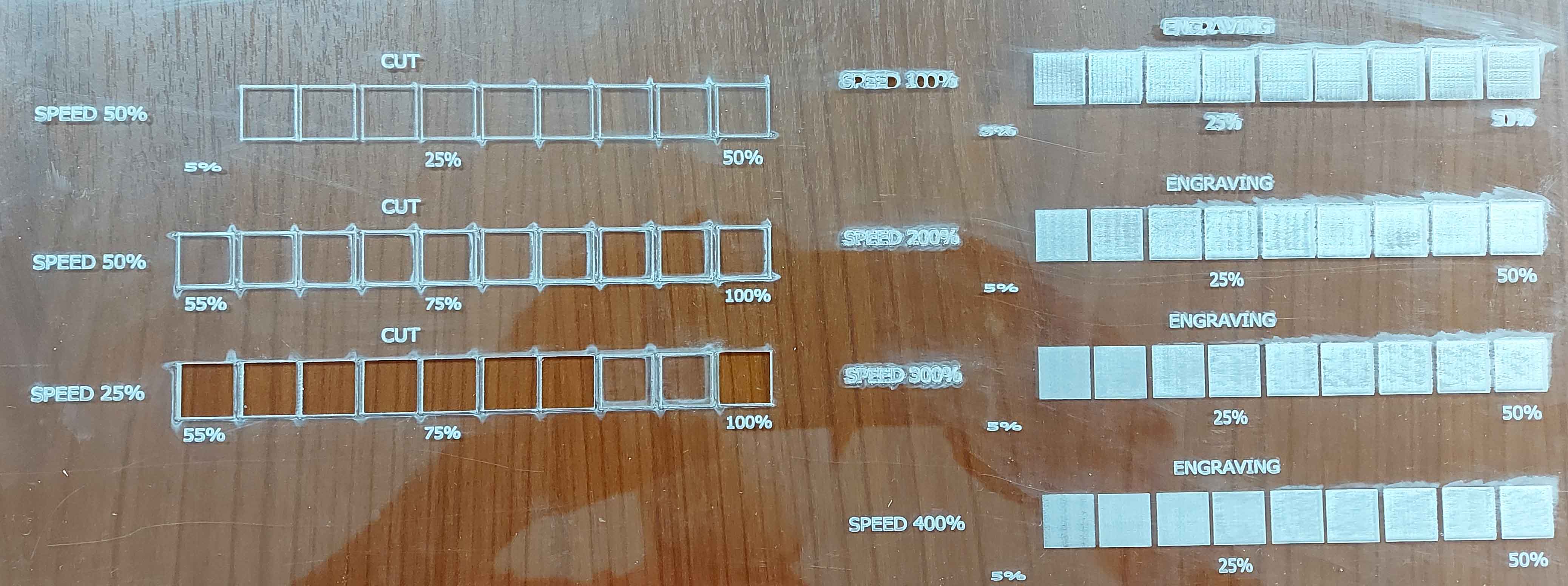
The laser machine has a 100W power supply. The machine was configured to make cuts starting with a speed of 100% and a power of 5%. rising 5% in each square until reaching 50% power. In the second row, it started with a power of 55% and increased by 5% until reaching 100% of the laser power. As we can see in both cases, the material could not be cut. in the third row the speed was reduced to 50% and powers were maintained from 55% to 100%, in all cases the material was cutengraving
For the engraving, an initial power of 5% was used and 5% was increased in each square, the speeds were varied from 100% to 400%, it can be seen that the machine does not perform any engraving with 5% power, A variety of grays can be obtained by changing the engraving speeds, but at a power of 35% and 100% speed I burn the entire square through all the material leaving a hole

3mm acrylic
Cutting
The machine was configured to make cuts starting with a speed of 50% and powers starting at 5% and increased 5% in each square until reaching 50% power, the material could not be cut with these parameters, in the second row The power was increased starting at 55% and increased by 5% until reaching 100%, but the material could not be cut either. in the third row, the speed was reduced to half 25% and the speeds were maintained starting at 55% up to 100% with steps of 5% in each square. in all cases the material was cut. less at powers of 90% and 95% the material melted, it stuck without being able to separate the cuts
engraving
The machine was configured to make engravings starting at a power of 100%, 200%, 300% to 400% of hairiness, the powers started at 5% and increased 5% in each square until reaching 50%, with this got different depths of engraving depending on the case. the deepest being 100% speed and 50% power where it almost penetrates the material
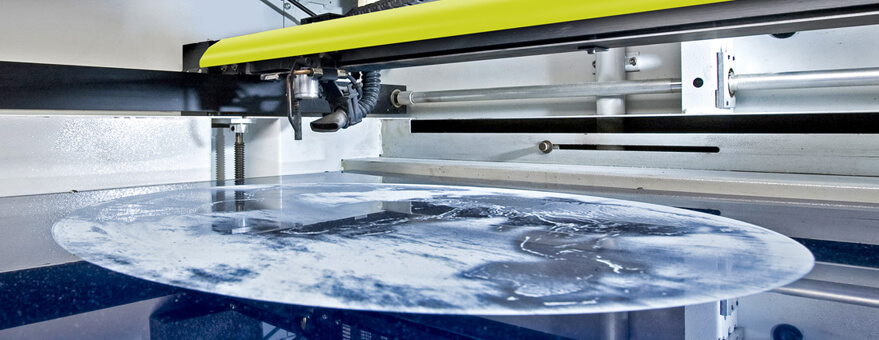
SETTING THE LASER CUTTER
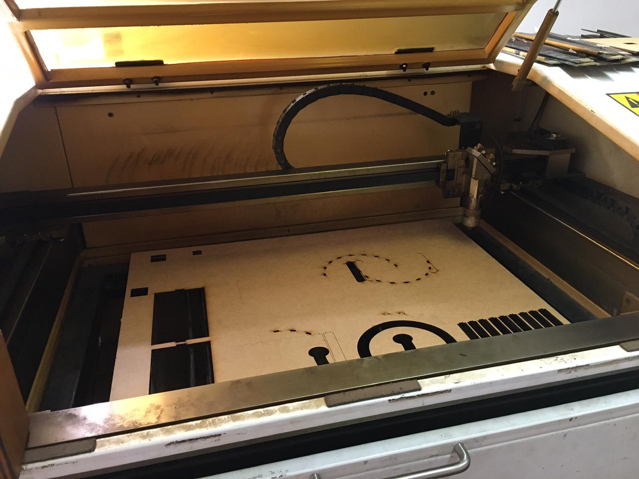
For this exercise we used a laser machined "made in Ecuador and hacked by ZOI" as our instructur said. It works for a 60x40cm format.
Workflow to use the laser cutter
- Turn on the machine, note that also the chiller and air pump must be powered on.
- Load the material to the machine, make sure it is flat if need secure it using masking tape
- Focus the laser on the material, use the 'focus meter' (a laser-cut piece that has the right dimensions 20x20mm) to set the correct hight above the material surface
- Move the laser to the desired starting position and set the origin pressing the origin botton
- If you don't know the kerf cut a small square and measure it.(it depends on the material)
- Prepare your files, better on a .DXF format, be sure you don't have duplicate lines or any extra path.
- The software used for the laser is RD Works.
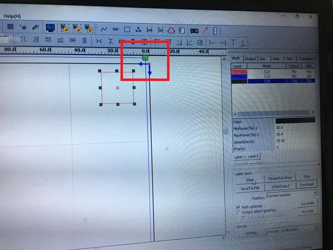
Important:This workflow has been updated with a new test where 1.5mm cardboard was used, and to do so, the parameters were also different from our group test - File >import > .dxf file
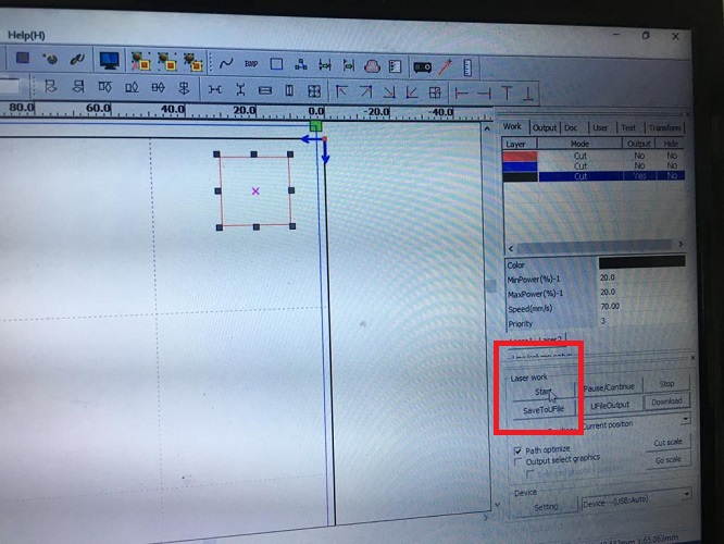
- The green square on the corner show the origin for the laser
- To make sure about the power and speed are the right ones for the work, and the material, it is recommended to draw an small square and try the parameters
- This square size is 20x20 mm
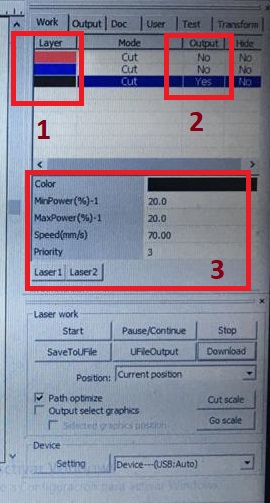
- Make sure of 3 important factors:
- The color of the layer, according to this you can set different parameters to cut or engrave. You can also change the order of this layers in the order you want the machine to work, for example firs engraving, second cutting (on priority).
- The output shows if you want to cut it or not.
- Set the parameters: min and max power, speed, and priority (thez order of the layers)
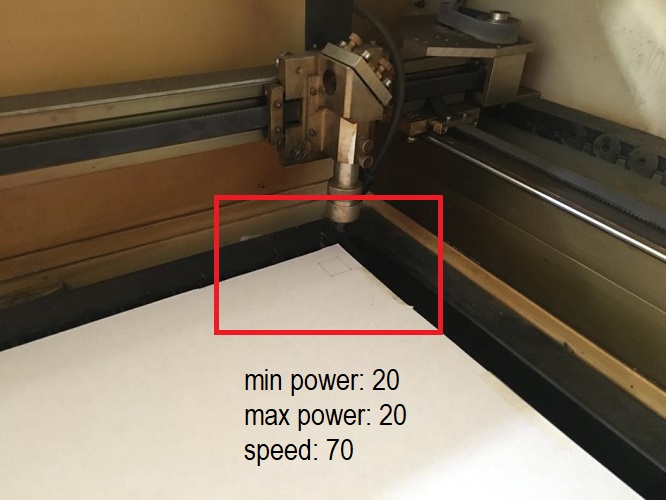
- For this exercise, we tried:
- Min power:20
- Max power:20
- Speed:70
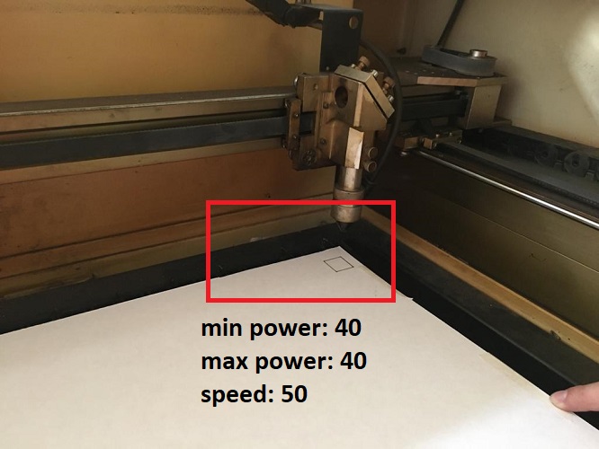
- Min power:40
- Max power:40
- Speed:50
- Once the parameters are ready you can click on start to send the square to the laser
- You can also, pause or stop during the cut if needed.
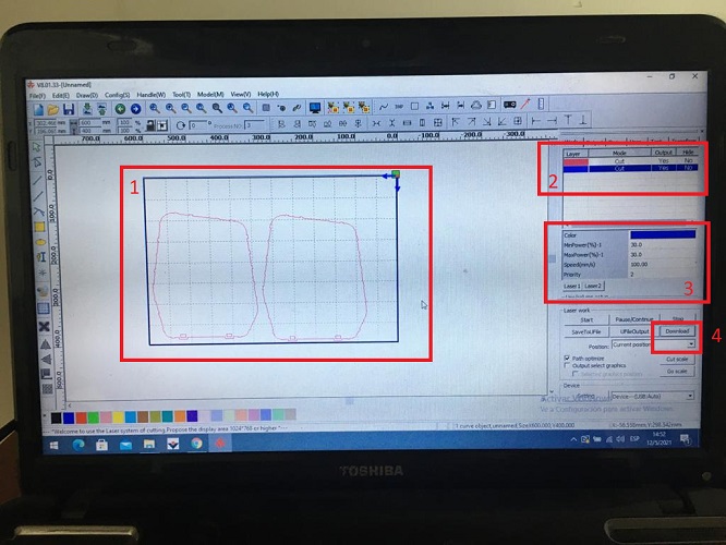
- Once the test is done, follow the next steps:
- Make sure all the drawing is inside the limits (60x40cm)
- Make sure the layer (color and order), output (yes or no, depending on what you need) and order is right
- Make sure the parameters are correct, min power, max power and speed
- Press download to send the file from the computer to the laser machine
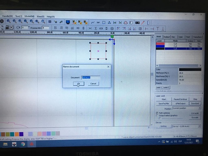
- Write down a name for the file
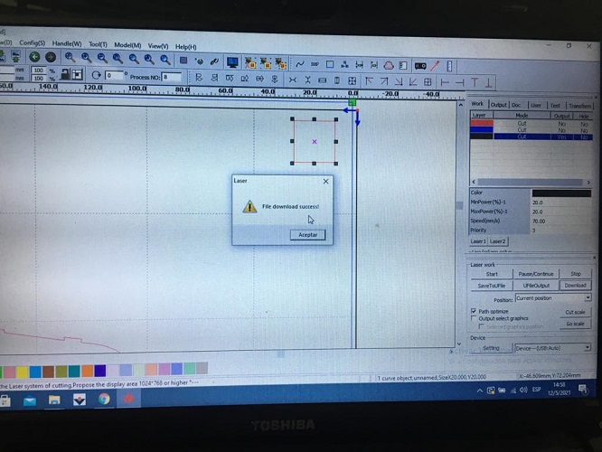
- When it is ready this message will come up
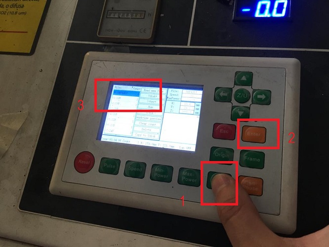
- On the machine, follow the next steps
- File
- Enter
- Look up for the file saved > Enter
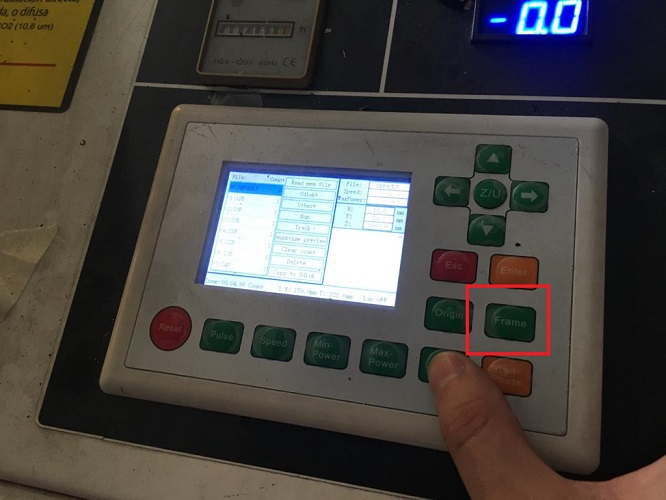
- Press frame to check that the file is within limits of the machine. In case it isn't a message will come up and the frame test wont execute.
In this case you should first check the file limits, or check the origin set on the machine.
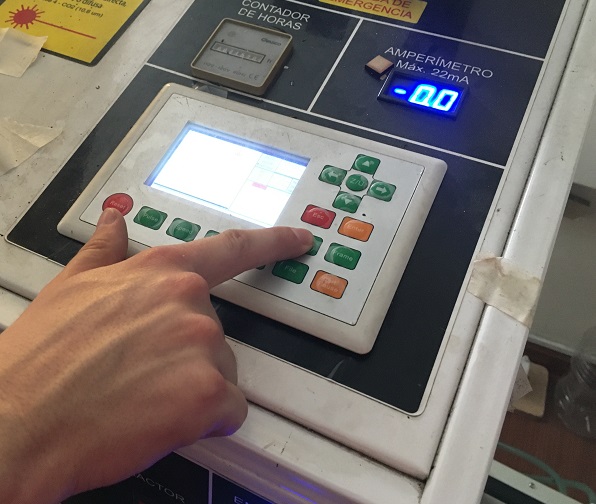
To set the origin on the machine, you can move with the arrows and press origin.
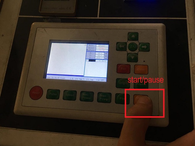
- Start (this same button can be used to pause
- Remove your pieces from the machine. In case the pieces felt on the base of the machine, open the front lid and take them out.
FIRST TRY
material: 3mm mdf
min power (%):68
max power (%):68
speed (mm/s):7
result: kerf 0.20mm, too loose, try a different kerf
SECOND TRY
material: 3mm mdf
min power (%):68
max power (%):68
speed (mm/s):7
result: kerf 0.27mm, pieces fit perfect
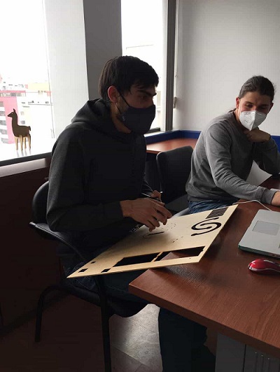
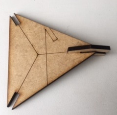
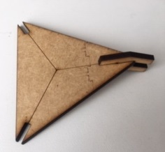
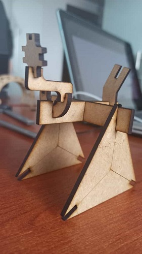
Once we had the kerf for this material we started cutting out pieces,
when they were ready we put all of them together. This was the result:
Camilo, Ismael and I worked on this on the lab and Jeffery worked remotely. Fortunately the lab has a camera located in the laser room and all of us could see what the other was doing in the meeting room and also in our computer screens while connected to google meets.