Week 09. MECHANICAL & MACHINE DESIGN
Group assignment
Mechanical Design
- Design a machine that includes mechanism+actuation+automation
- Build the mechanical parts and operate it manually
- Document the group project and your individual contribution
Machin Design
- Actuate and automate your machine
- Document the group project and your individual contribution
Here is the link to the group assigment page.
Machine Design
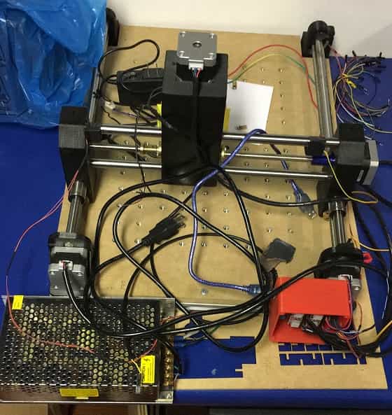
We realized that our lab needed a machine to drill PCB. As a starting point we used small CNC machine apparently not ever have been used. The is to use laser to Home the axis instead the final switches to have better precision
Check actual status and find out how it works
When checking the axis movement we note that the Y axis which is the longer one in this machine move too noisy, after some test the problem was that the sides of the the axis where no aligned. As the threaded Rod have just one side fixed the start position of each side depends in this design in the machanichal initial position when assembly the lead screws on threaded Rod.
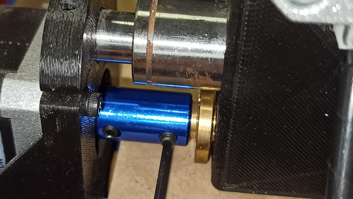
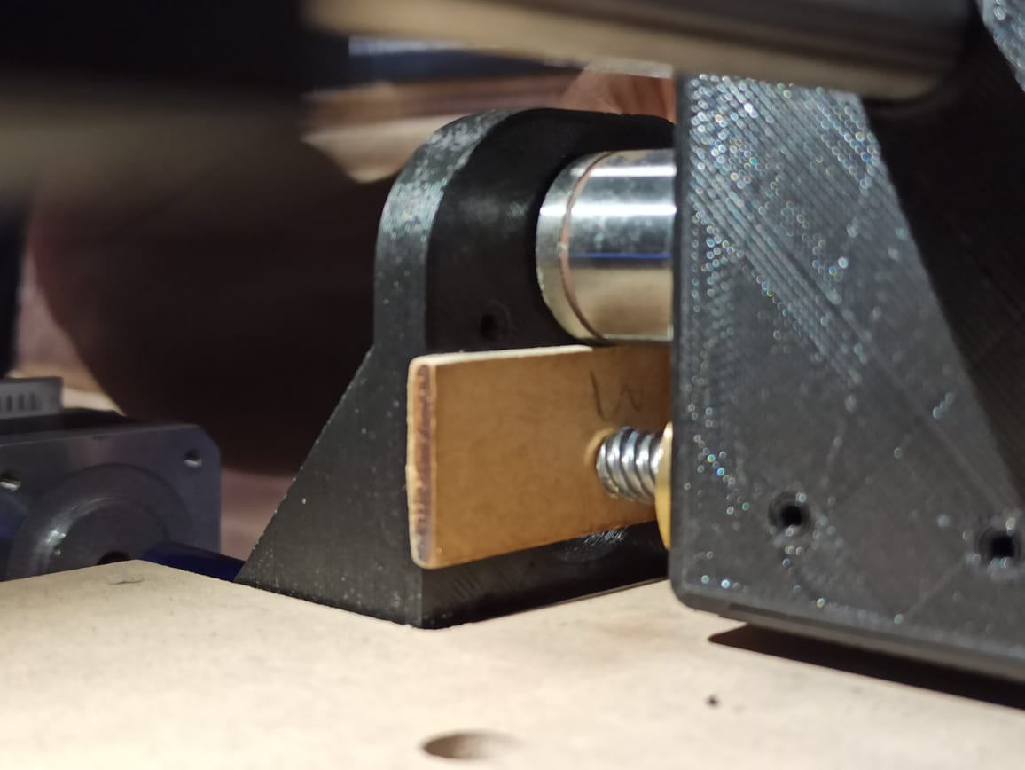
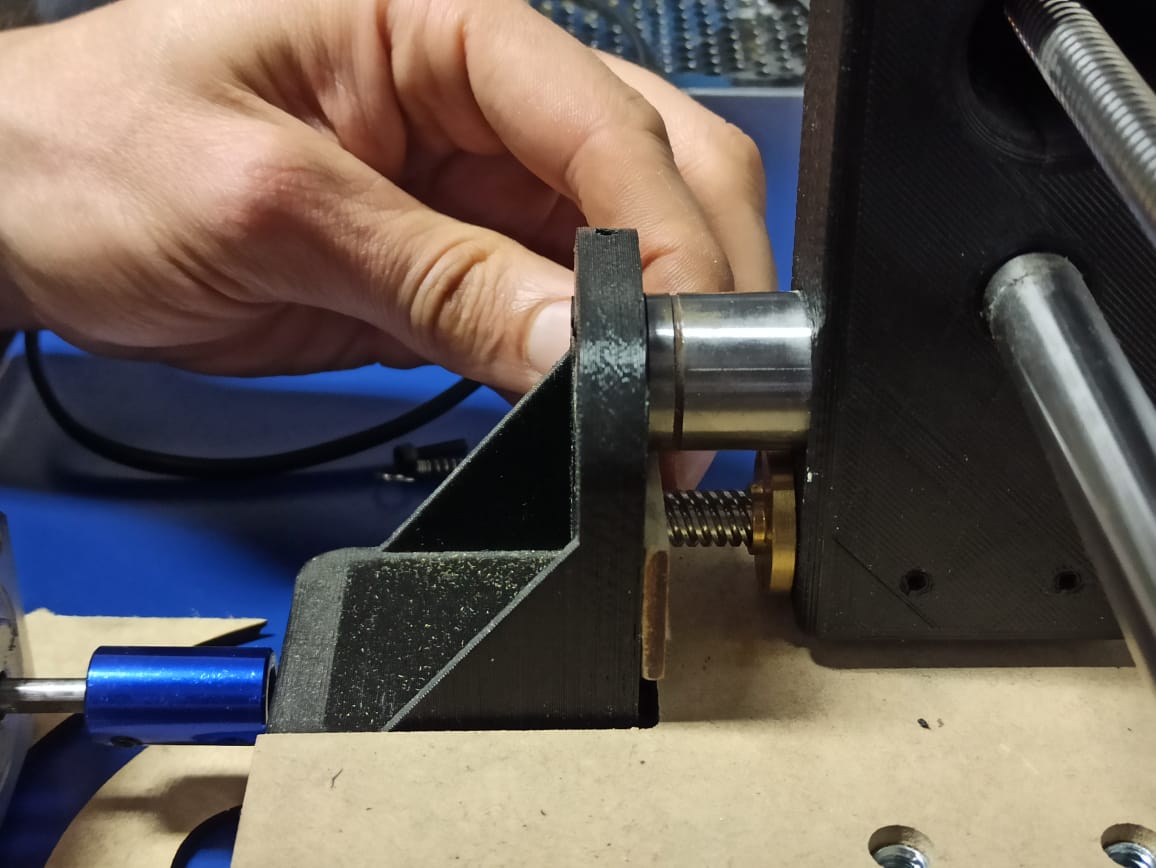
After this mechanichal alignment the axes of the machine move without problem and we have determined to use lasers so that the machine can identify the origin. We will use Bcnc to control it.
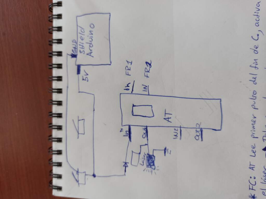
Circuit Board
Isma and I thinked about a schematic circuit to make a pcb to hel us to align the axis instead of the final switches.
Milling
We look on Internet an autolever workflow because we suspected that the other workflow have been used was not working well and we found one worked really well for us. I leave it here. with the use of bCNC.
USE OF bCNC SOFTWARE
You can find a guide of how to install this open source Sotware HERE
bCNC is very usefull and there are a lot of information about it which is really helpfull. I will do this guide accross the steps on this tutorial if you want to watch it.
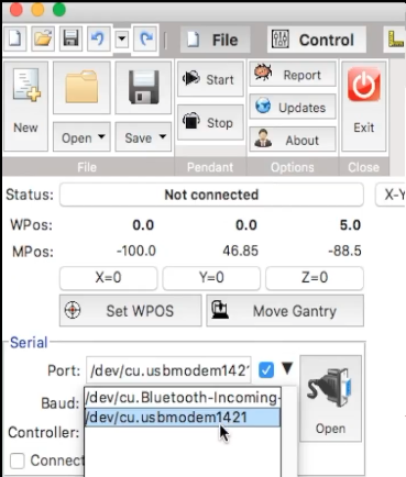
Connect to serial
It's important to mention this software is intended to use as GRBL CNC command sender and GRBL is recommended to work with Arduino so we are going to connect with the same COM port Arduino is connected as shown in the images below.
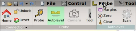
In the top bar we can find different menus we will use to do a milling or anything your machine and G-code are intended for. When bCNC open the defalt menu is "File" where the serial conection can be found. Next to the right we can see "Control", "Probe", "Tools", "Editor". every menu have different options we will find through the nexts steps.
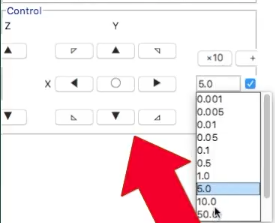
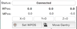
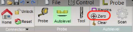
Control
In this menu we can find the controls wich allow us to control the machine, in the top part we can see the Home button that take the Spindle to the cero point pre-configured in each axis. Unlock and Reset help us to take the control of the machine after chrushing or for any reason having an alarm activated.
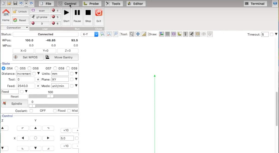
In the lower part we will find the arrows wich allow us to choose the direction of the movent in each axis.
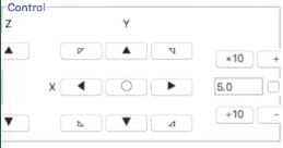
To the left there is a listbox where we can choose how many units each click will value, if your machine have no limit switch you have to be really carefull and choose right to not crash and cause any damage.
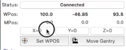
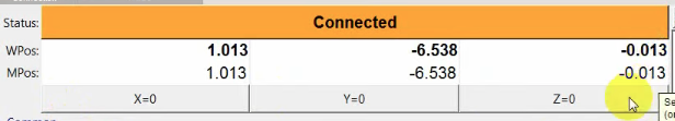
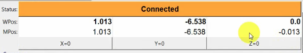
Bellow "status" we can see a relative position in each axis, this position is relative to the last cero set in each axis did by user
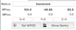
We can click on the button X=0 Y=0 Z=0 to make the actual posion the cero position, this potition it's not equivalent to the one stored in Home button, be careful with that
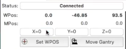
The position where is the point of interest to start milling is where we should cero the position on each axis so we can continue with the autolevel process.
Autolevel
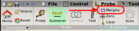
Before Starting this process is important to open the G-code file we want to mille on the top bar menu, go to file, then open and select the correct one go to Probe in the top menu and click on autolevel
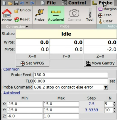
If you know the area of your milling space you can write it manually here, know that z parameters means how much the tool will go down and how much will go up to a safe distance. In this picture will down -1mm and up 1mm.
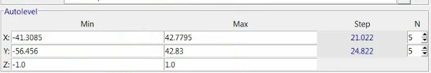
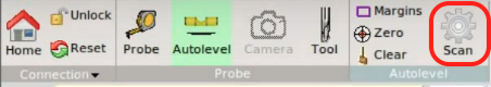
However I recomend to click on margins to make the programm select the area automatically, the you can choose the number of scans you want to make in that area, of course more points of scans makes better precision but takes more time to complete the scan, in the lab we use 7 scans and it's enough to have good results.
Then you can start the Scan process but be carefull. Note: To scan we have to use a sensor depending on the material you will work, if the material have good conductivity properties you can use a conductivity sensor, if not, you have to use a pressure sensor or similar. If you do the scan without a sensonsor or any probe tool the machine will crush against the material.
Now go to probe
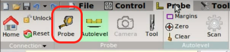
In Probe we will set the zero position of Z axis to ensure the depth of milling will be done with accuraccy.
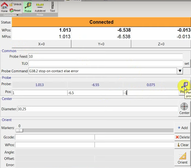
Once you click on the probe icon and the tool touch the material we have to make in this coordinate the zero of Z axis
Now a very important step is go back to Autolel and press the Zero button, withoth this step the zero on Z axis will be wrong and the autolevel will have no sense then.
Things almost done, remove the sensor you are using, if your spindle turn on manually this is the time to do it and then on the top menu go to Control and click on Start. Now the machine should start milling well.
Soldering Limit Switches and another components
As the machine didnt have any switch I did a lot of work soldering a lot of cables to the final switches, the main power button to the power source and so on. It was a long time doing that and also some burnings. the conections of the rele module to activate the Dremel used as spindle and helping Isma trhough the way on checking the program and things related to electronics and programming.
Some thoughts About this weeks
As always a lot of learnign come doing things. This time was really interesting to try to modify the way a machine work but not just mechanical. As GRBL CNC have a code which use a standard way to do the homming process, hack that way of working without touching the original programming but instead making a PCB and programming it to make the machine work as we wanted for was a very interesting process.