Week 07. Computer-Controlled Machining
Group assignment
- Do your lab's safety training
- Test runout, alignment, speeds, feeds, and toolpaths for your machine
- Document your work (in a group or individually)
Individual assignments
- Make (design+mill+assemble) something big
Have you
- linked to the group assignment page ✓
- Documented how you designed your object (something big)✓
- Documented how you made your CAM-toolpath✓
- Documented how you made something BIG (setting up the machine, using fixings, testing joints, adjusting feeds and speeds, depth of cut etc.) ✓
- Described problems and how you fixed them✓
- Included your design files and ‘hero shot’ photos of final object ✓
Group Assignment
Here is the link to the group assigment page.
Making Something Big
CNC machining is a manufacturing process in which programmed with computer software that writw the coordinates the machine will follow and other instructions as the spindle speed, feed rate, needed to achive the results we want and of course with safety. This instructions are called G-code and dictates the movement of factory tools and machinery. The process can be used to control a range of complex machinery, from grinders and lathes to mills and routers. With CNC machining, three-dimensional cutting tasks can be accomplished in a single set of prompts. But this week is based in 2D machining.
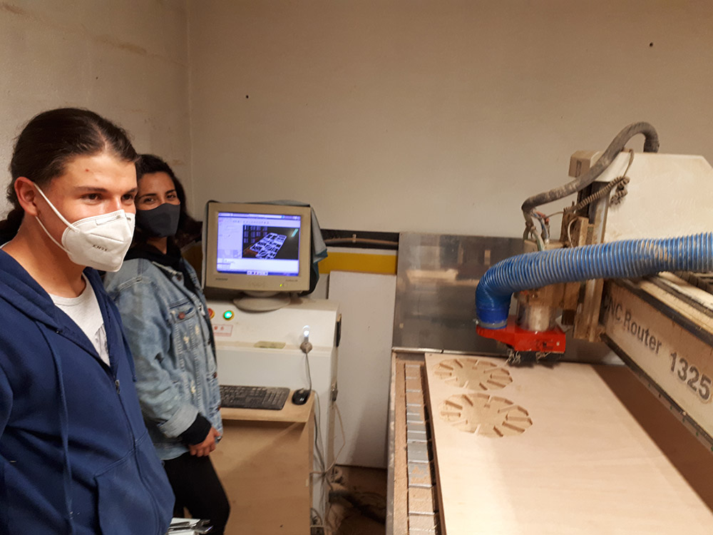
The machine we use in ZOI is called Router 1325.
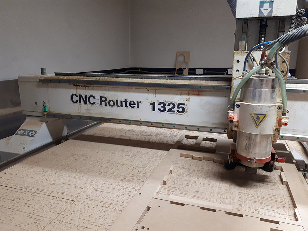
Characteristics
- Number of axis: 3
- Working area: 1300x2500x200mm
- Softwareused to generate G-code: Artcam
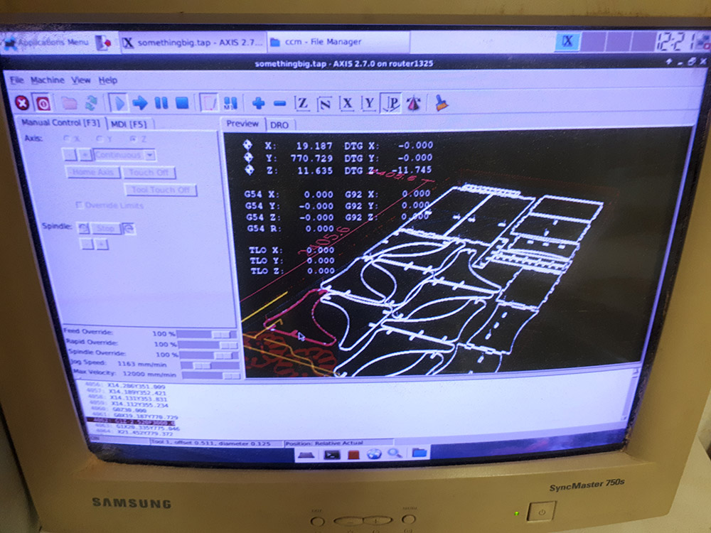
- Software wich control Machine: LinuxCNC
This week I wanted to do something usefull to human size and I decided to do something to leave the shoes before enter home, a place to sit and also leave an umbrella. I measure the size of the place this forniture will be placed and start making a sketch.
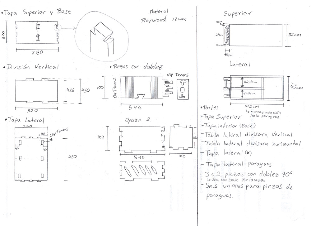
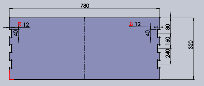
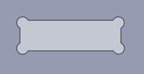
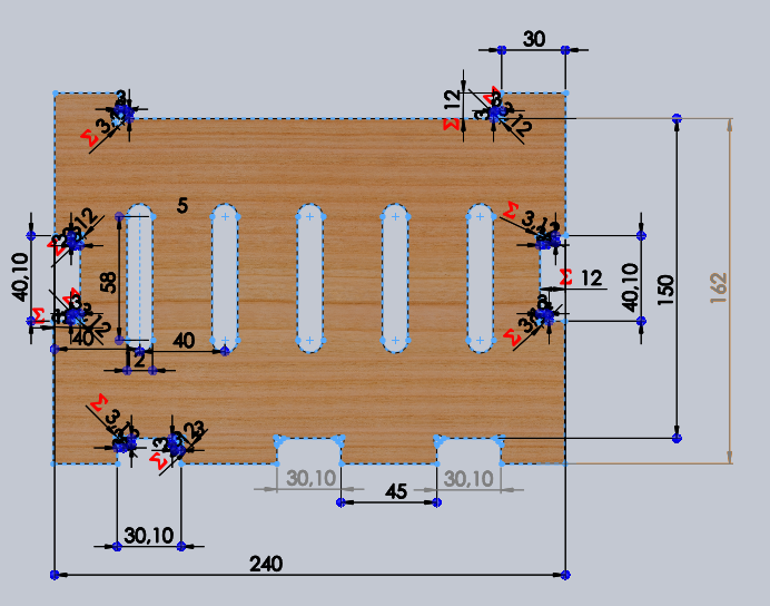
I wanted to do some pieces that can be blended but because of the time will be impossible to do test so I decided to do straight pices. As other design process I worked with SolidWorks. I start designing the base wich will be the same piece to sit on.
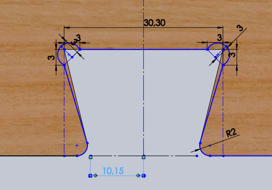
Then designing the Dogbones that wich allows the pieces to fit. This is beacause the diameter of the tool and because the milling process itself. This video explain why dogbones are needed very well.
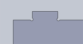
After repeating the process and make all de pieces with dogbones we did a press fit test to know how much shold be the offset to achive the result we want.
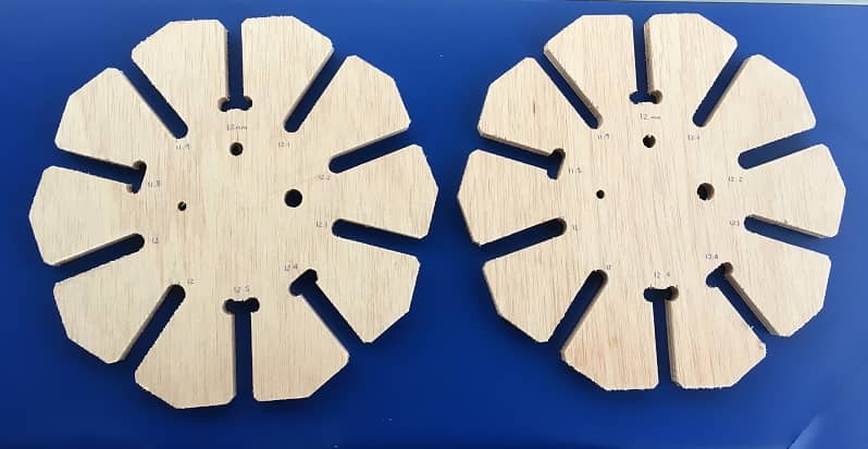
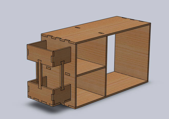
As my desing shold be strong just using a strong fit I decided to go with 0.1 mm offset wich allows the pieces to insert and the fit is really tight. To be carefull and test if everything is okay and also to visualize how the design will looks like I did a SolidsWorks assembly. After doing this changes in software using equations and global parameters so I can change the pieces if I change the material or some change is needed we prepare our pieces to be machined. We use 12mm playwood with the size of the bed machine 1220mmx2440mm. Some pices of my design didn't fit in it so I couldn't have everything that day.
Using Artcam
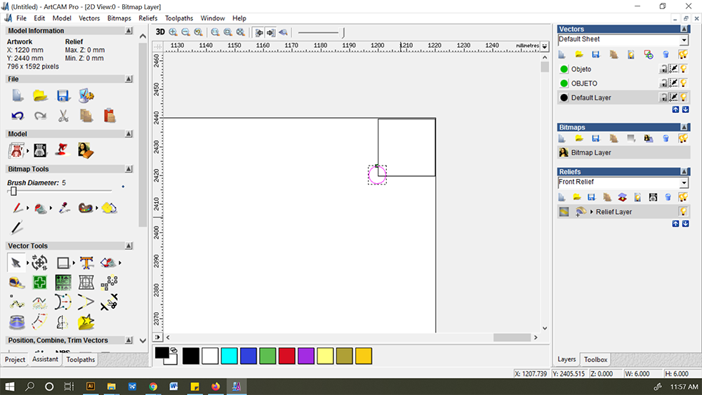
- Select the nesting .dxf file and open it3
- Place screws in the drawing so the machine make holes to allow a screw go though easy. Place the screwsit in the corners with a 4mm diameter circle.
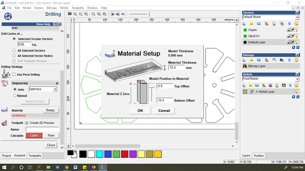
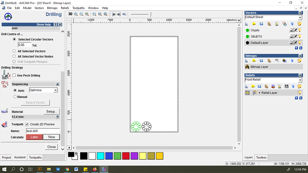
- Go to drilling options
- Set following screws parameters:
- Start depth:0
- Finish depth:12.6
- Machine safe z: 30
- Tool: select> routing and 2D finish> End mill 1/8 inch ZOI step over
- Material: setup> material thickness: 12.4mm > Model position in material: top offset: 0, bottom offset: 12.4mm. Depending on the material.
- Go to toolpath > name now > write name and save
- Go to Profiling options where the milling parameters will set
- Prolifing tool: routing and 2D finish> End mill 1/8 inch ZOI step over
- Toolpath: name> now> write name
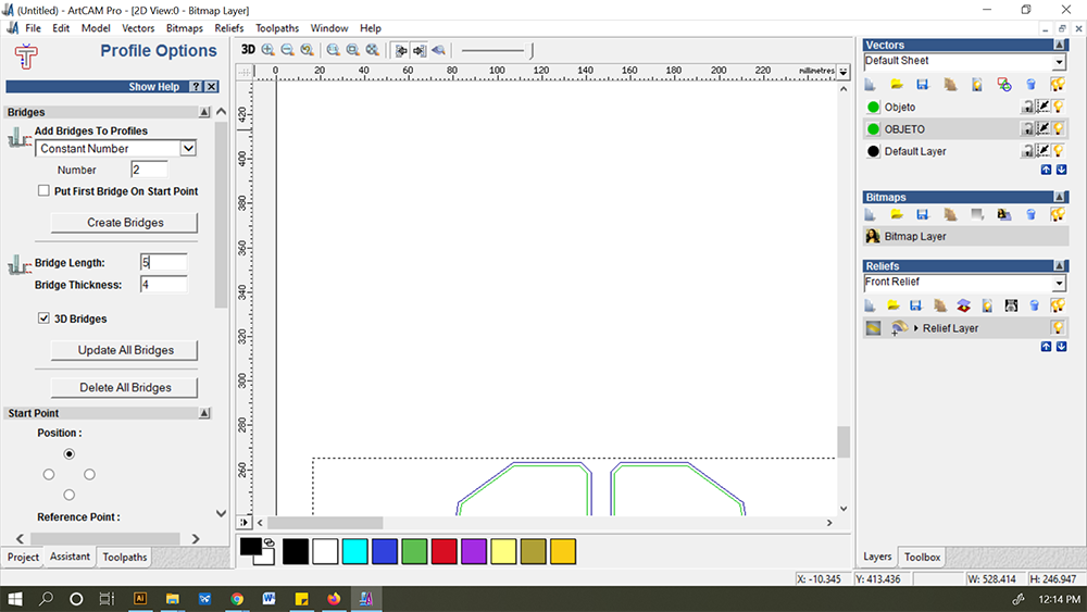
- Profile options where we will place the bridges
- Add bridges to profiles. Number: 2
- Bridge length: 5
- Bridge thickness: 2
- Double click were bridges will be placed
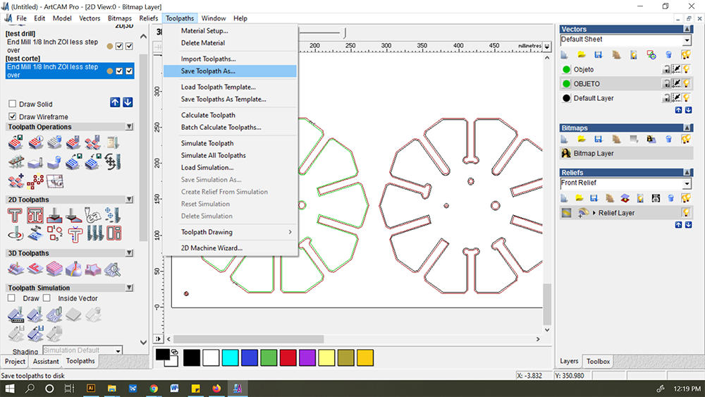
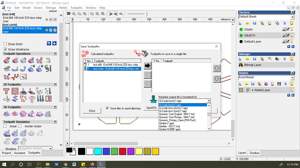
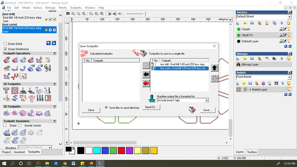
- Save Toolpath
- Select the archive from the list
- Save it with .tap extention
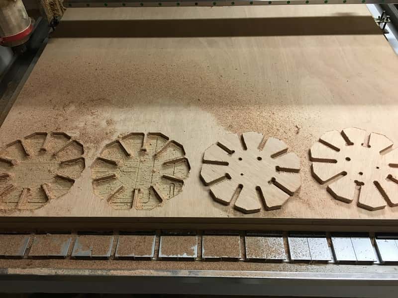
CNC Machining
Results
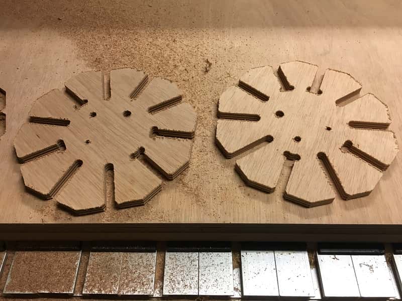
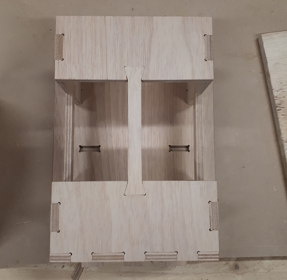
The four pices that fit into the playwood size ready to test.
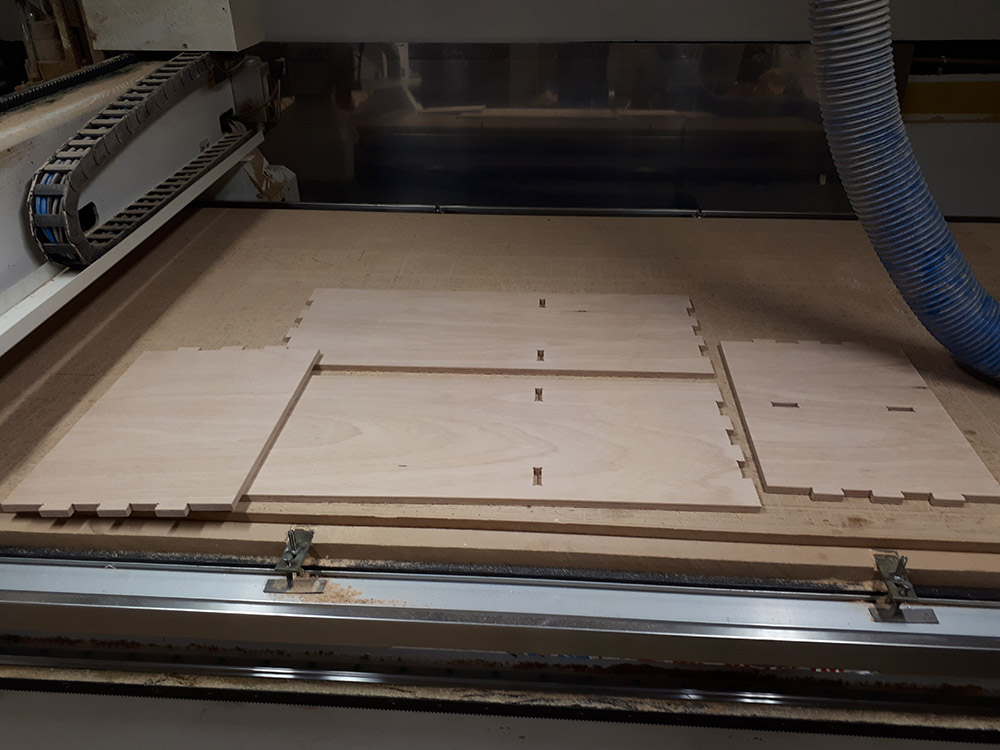
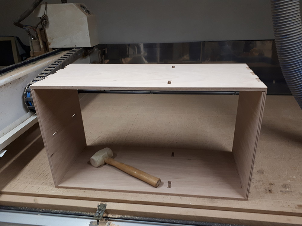
The joints felt more loose than I spected even with just 0.1mm offset, but tight enough to need the rubber hammer to do the work.
The past days I could not finish the rest because there was no one in the lab to supervise my work when I planed to use the machine so I hope to do it soon and update the final picture.
Update 19/03/2021
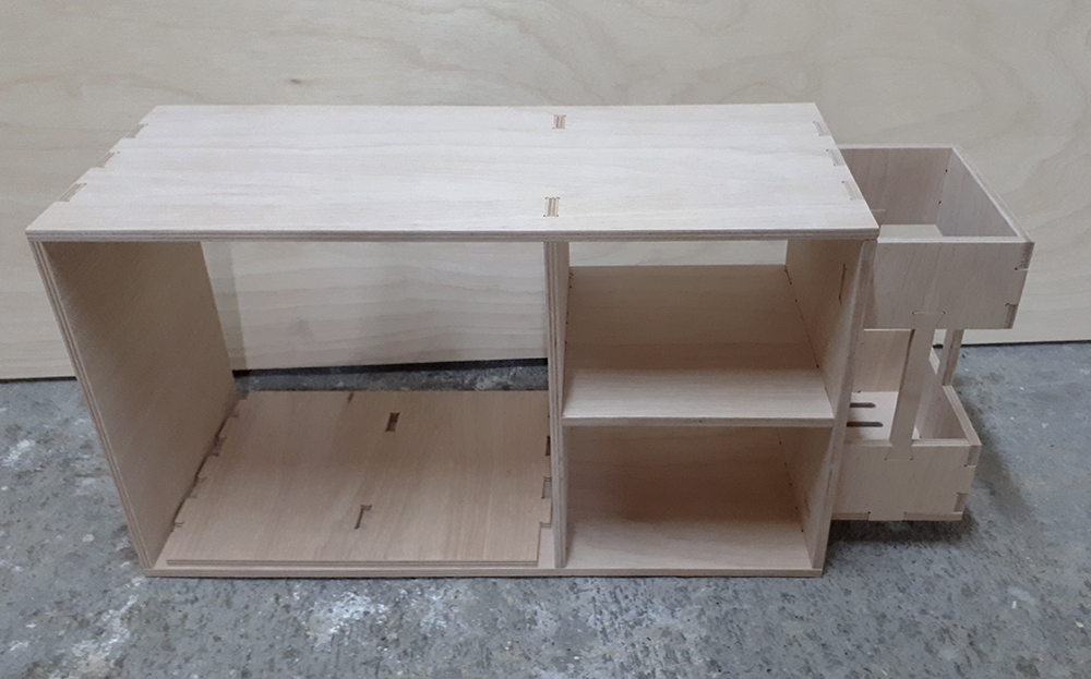
Finally I finish the forniture, the pices that were left to cut are ready.
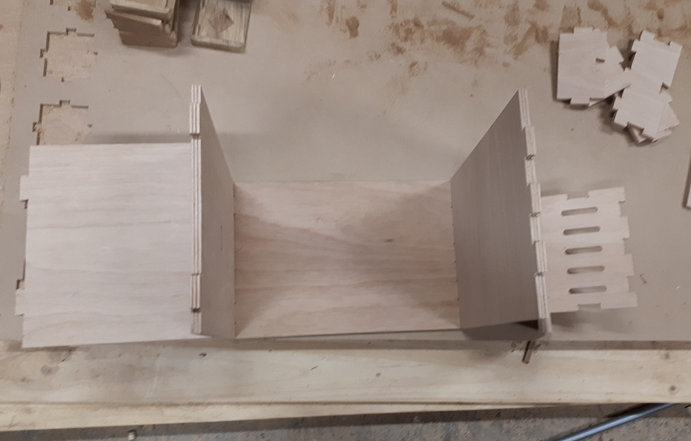
After sanding this pieces I start to assemble everything, I started in the side umbrella holder, and the pieces wich are in the middle of the forniture.
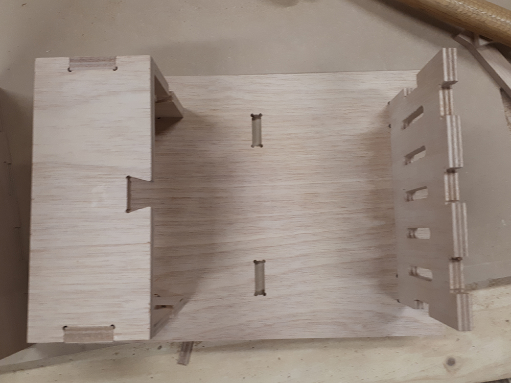
The fit was perfect, needing to hit several times with the rubber hammer to assembly just as I wanted to make it stable and for preventing some loose joints. And here is the forniture complete assembly.
And finally in the place forniture was designed for and the use of it. It's important to know it's made to sit on it, to take the shoes off or put them on. I'm happy with the results.
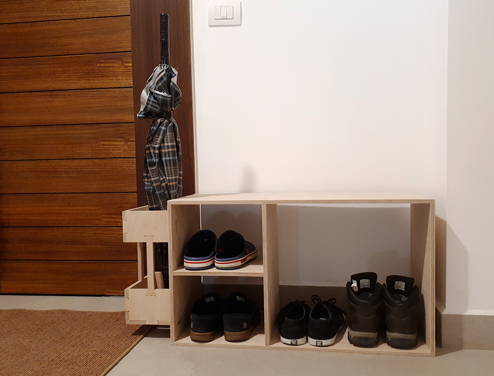
And finally in the place forniture was designed for and the use of it. It's important to know it's made to sit on it, to take the shoes off or put them on. I'm happy with the results.
Final thoughts
As our imatination flies the possibilities to create amazing looking designs using wood it's unlimited, this time I did a kind of square design but milling, math and advanced design software open the possibilities of creation and I appreciate the work of people who did such a beatifull imaginative designs.