Week 04. Electronics Production
Group assignment
- Characterize the design rules for your PCB production process: document feeds, speeds, plunge rate, depth of cut (traces and outline) and tooling.
- Document your work (in a group or individually)
Individual assignments
- Make an in-circuit programmer by milling and stuffing the PCB, test it, then optionally try other PCB fabrication process.
Have you
- linked to the group assignment page ✓
- Documented how you made (mill, stuff, solder) the board✓
- Documented that your board is functional✓
- Explained any problems and how you fixed them ✓
- Included a ‘hero shot’ of your board ✓
Group Assignment
Here is the link to the group assigment page.
Make an in-circuit programmer
To complete the assignment of this week I build the FabTinyISP according with the instructions in this link. You can find all the information needed to do it except for the milling process. The reason is there are different processes for milling depending on each machine. So you have to learn the milling process according to the machine you will use.
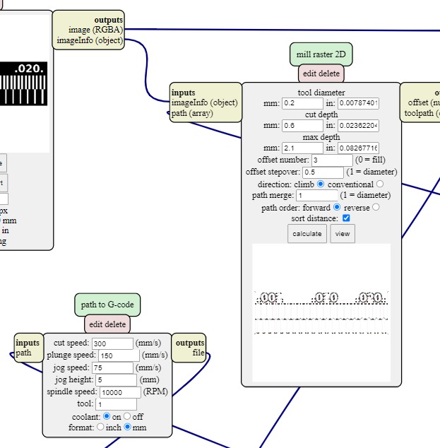
The group assigment consist in characterize the design rules for your PCB production process and we worked in traces .png first. To generate de G-code using mods right click on the image --> programs --> open server program and select "mill 2D png" and then follow the work flow.
- Select .png Archive
- Fill the information in mill raster 2D according the tools you have and the results you want
- Fill the information in path to G-code according the machine you are using, the process and of course the safety parameters
- Click on Calculate (raster 2D box)
- And you have the G-code 😮
- Don't forget to verify everything is okay with the G-code (more details below)
So here you can read something that happened during the milling process...
In Fab Lab ZOI there is a "hacked" 3D printer wich now is a milling machine. When we were milling the Group Assignment something weird happened and the machine drill too deep going though the cooper plate and even reaching the spoil board of wood. That was unexpected because before starting the milling process we verify the G-code in G-code simulator and everything looked good. The incident damage the tip of the Milling bit and let the colum of the motor loose. The consequences forced us to use a different CNC freesmachine, the big one.
Basically the process to work in this machine are the same to generate the G-code but the use of the machine is different starting in the fact this ONE works on linux sotware something that according to Diego (he work on Fab Lab ZOI) who helped us through this process, the software is more stable and prevents incidents as the one I told you.
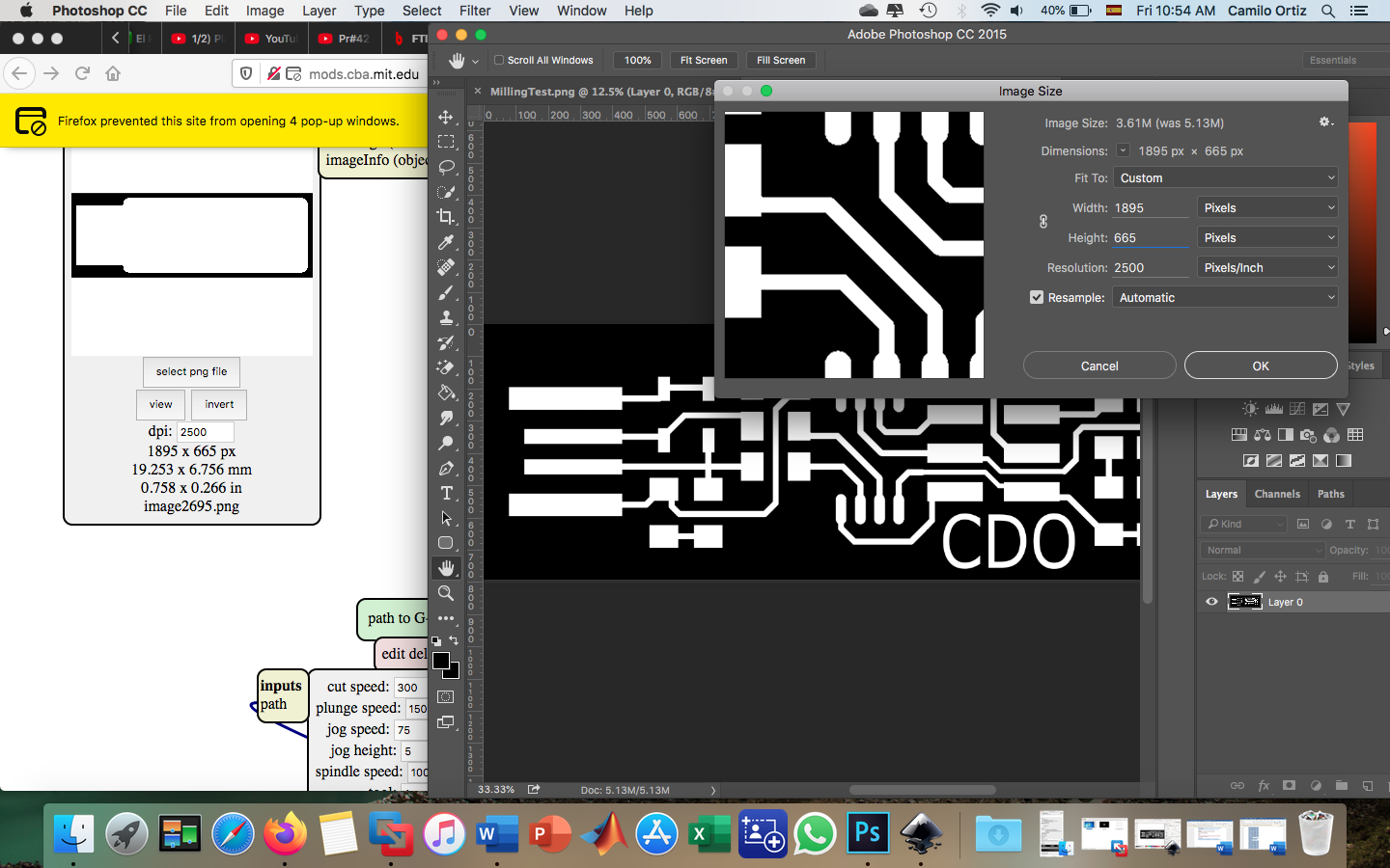
Another problem happened during the process of modifying the .png archives to put my name inicials, even when I was carefull to don't change the size or the resolution of the archive while editing, well, it happened. To edit the archive I used Gimp but in order to change the size and resolution to left it in the right way I used Photoshop and problem solved.
After milling the first test that was okay until the cut part, because the milling beat used for each process were different the ones we use in Fab Lab ZOI are in the imege below.
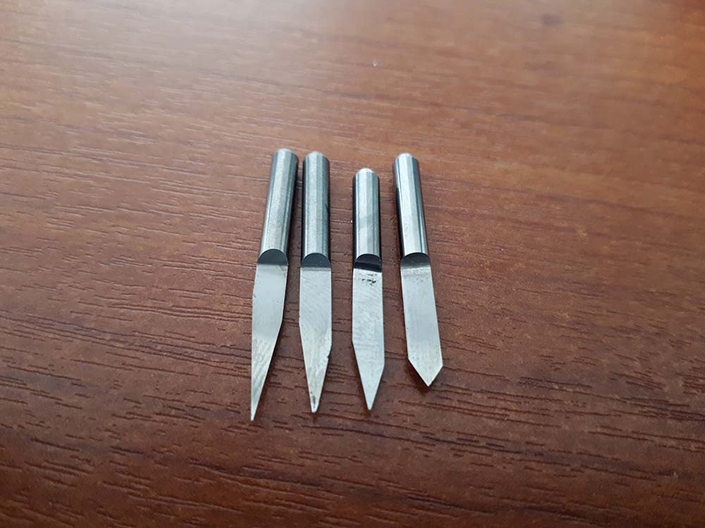
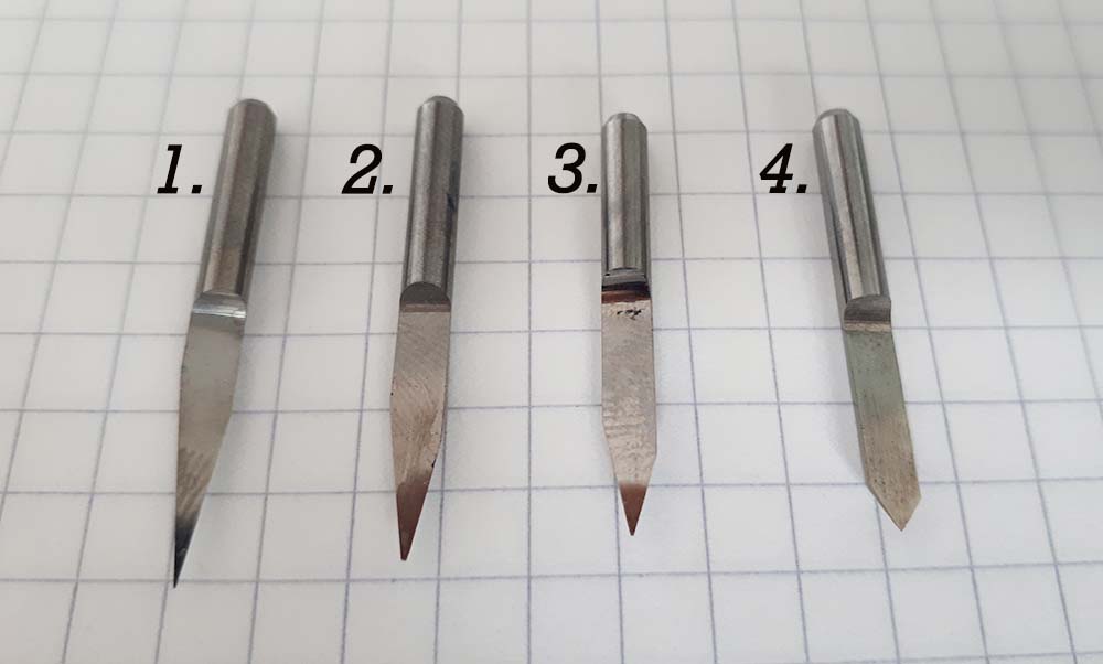
We used the #1 to make the PCB and the #4 to cut and we underestimate the relation between the angle/depth. Below are the parameters used to cut the PCB. The tool diameter were not considered in the right way so the result was the angle of the milling bit cut more than required.
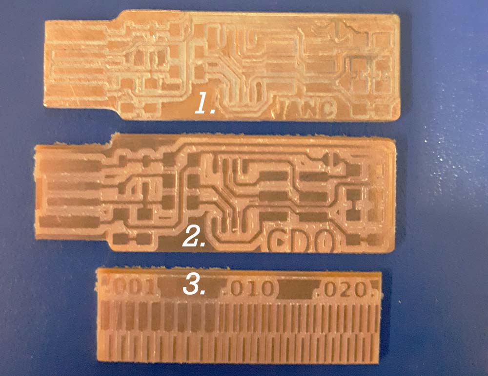
The PCB #1 loose one trace, the PCB #2 have been fixed by change the tool diameter to 2.0mm because of the caliper measurement and #3 is the traces PCB Neil taught in class. Once the traces PCB and FabTinyISP PCB were milling succesfully it was time to prepare the components for soldering them.
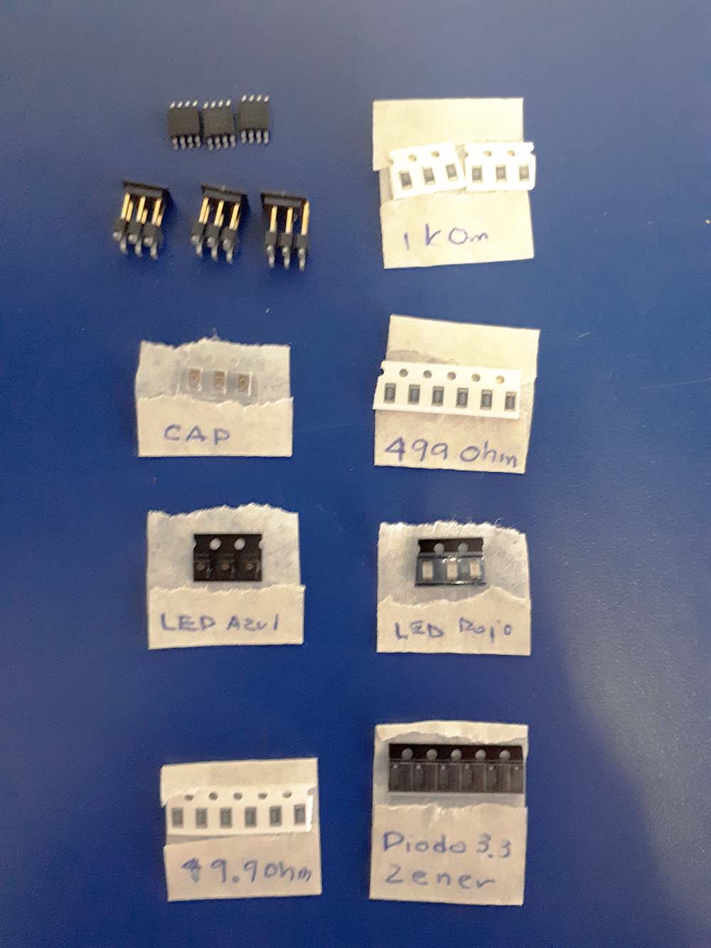
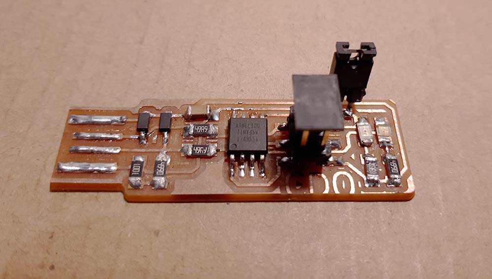
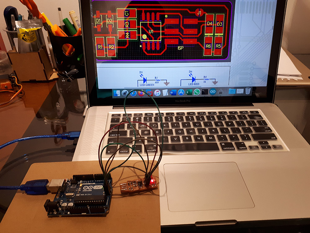
As we classified the components before soldering them I trust in that process so I dind't care too much obut the resistor values, but I wanted to be sure and the miltimeter I used didn't work for some reason so I continue soldering. The next day when I had everything in place I decided to review the the PCB so the first thing I did was look for the resistors values and guess what... Yes, the 49 Ohms resistors where in the place of 499 Ohms resistors so I had to change them. When I was soldering I wad some jumpers pins in the soldering station so I decided to use it insted of shorcut with tin. At the end I think the programer looks good, now, programming the ATtiny45 it's pending but the development environment it's already set up waiting for the programmer.
Trying Arduino as ISP
Failure Attempt
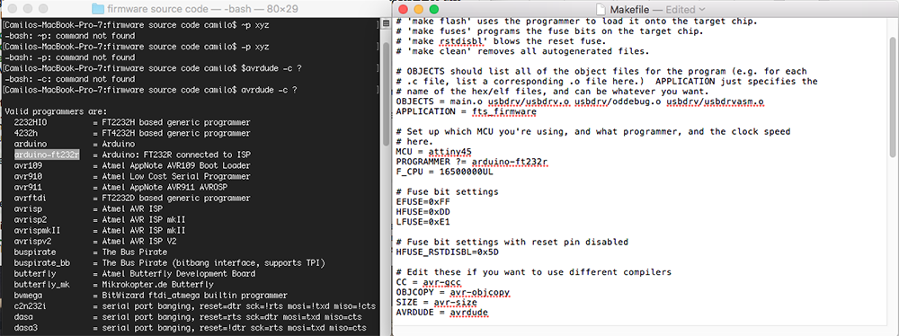
I have an Arduino Nano so I wanted to use it to download de .hex file into the ATtiny45, Isma who is doing the FabAcademy too told me that he tried to do it with half of success because he charge the .hex file but the usb controller have not being reconized on his computer. With Arduino Nano has not any progress because it was not reconized by avrdude but when I used an Arduino UNO it has been reconized. First thing to do it is to change the MakeFile to put the programmer I will use and the target microcontroller.
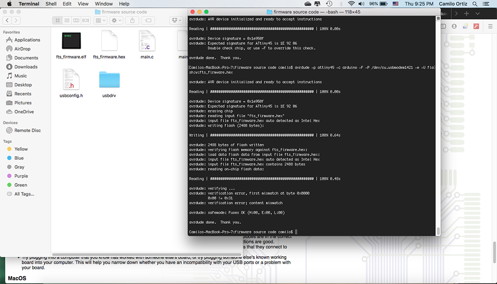
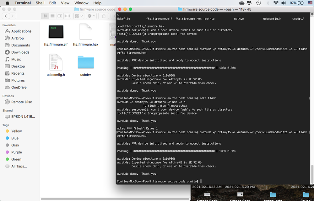
The use of "make" has no effect in my case so I had to write the command lines as shown and copy from arduino IDE the USB port where Arduino is connected. And it looked like .hex file has been written succesfully but there was a concerning message about some direction on ATtiny45.
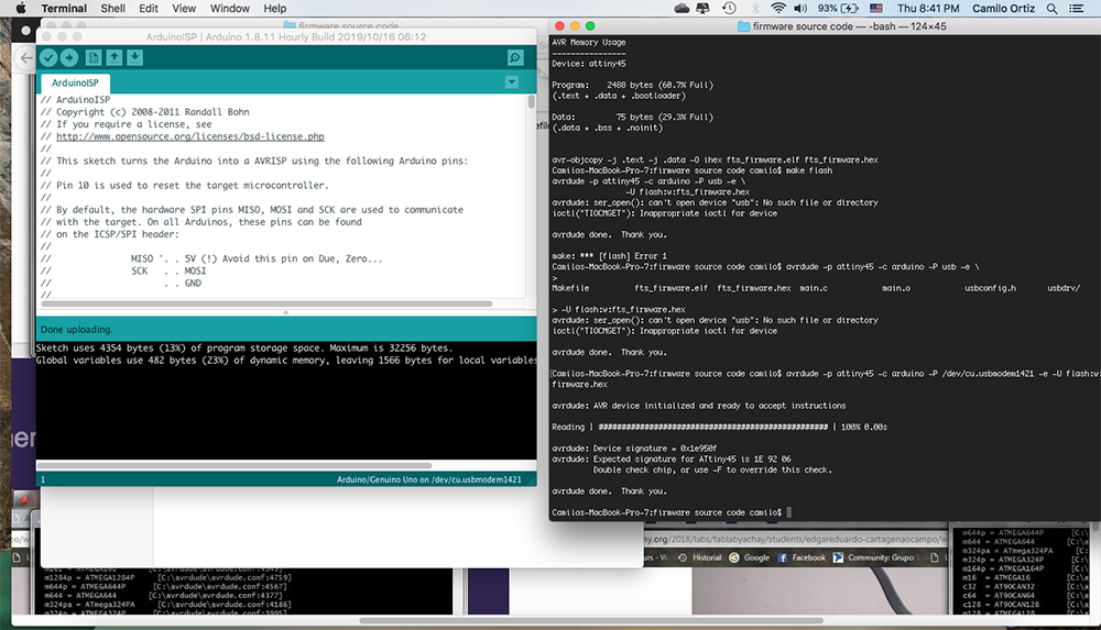
The same happened when I used "make flash" so I had to write the commands again but there has an error again.
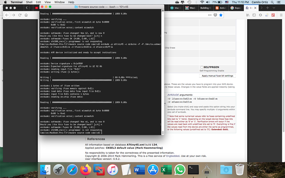
After several times on repeating the same process I decided to reload the standard fuses on the ATtiny45 so the first error whe I tryed to use "make" could be solved and then the other problems. To do this I went to this Page where you can see the fuses directions in different AVRs microcontrollers. So I copy the "default" fuses on the Attiny45 and burn them. This process had no problem.
But again the same error appeared again and again. U tried to insatll some libraries and a lot of different thing until I accept it won't happen.
Programming with an ISP programmer
Succesfull Try
Now I tried with the proggramer Alex did in Fab Academy 2018. The same process, different programer.
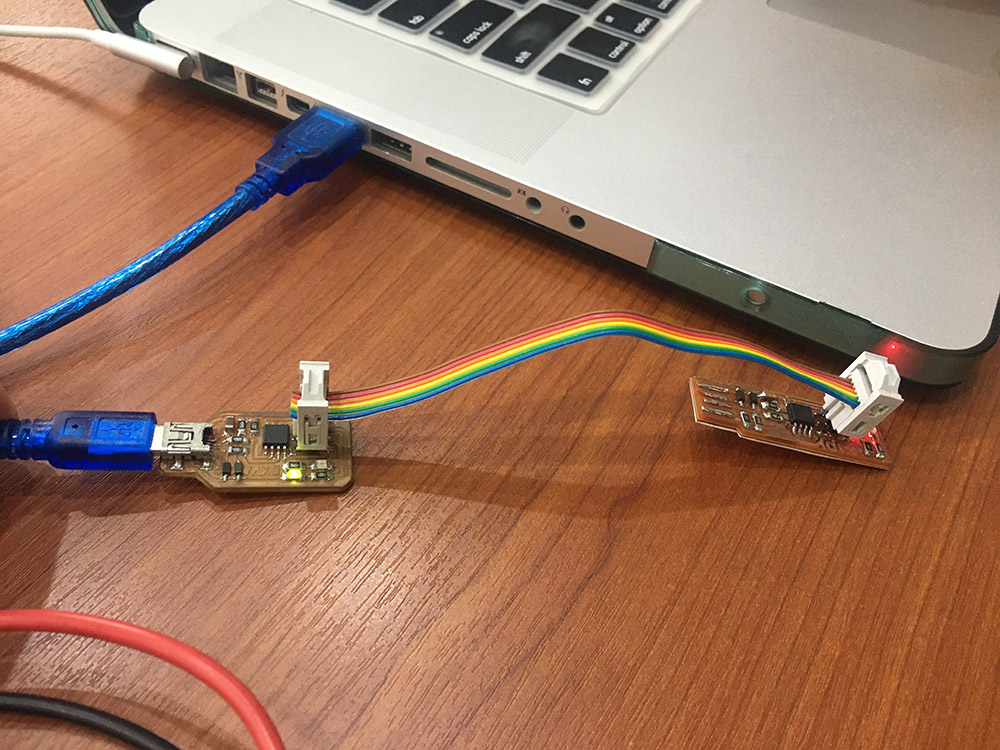
This time the things were smooth and the process just happened with no problems
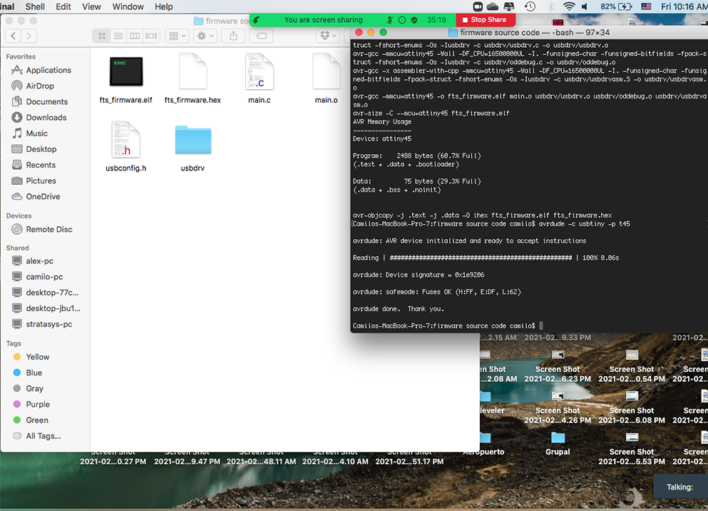
After "make" with no error message burn the fuses --> "make flash". Something important to notice when doing the
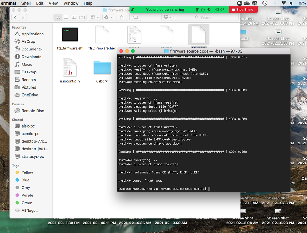
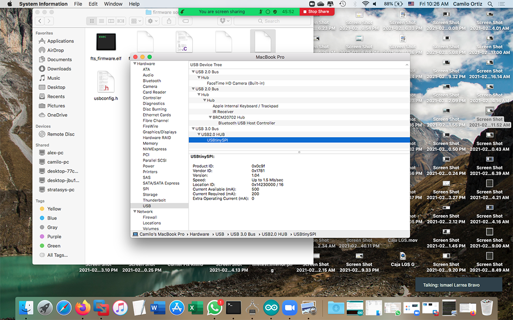
And finally after burn the reset fuse "make rstdisbl" my Attiny ISP was reconized in my computer