Final Project
What is it?
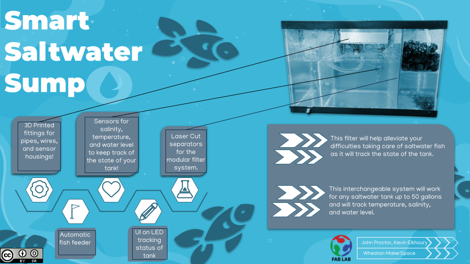
We built a modular fish tank tools including a sump and automatic fish tank feeder for now with the possibility of additional features being added in the future. These new features can be added as addition modules to be connected over our I2C bus with the Rasberry Pi serving as the master device. I did this project in conjunction with John Proctor who mainly focused on the sump while I mainly worked on the Feeder and hooking everything together with the Pi and the UI. You can check out his website here!
We built a modular fish tank tools including a sump and automatic fish tank feeder for now with the possibility of additional features being added in the future. These new features can be added as addition modules to be connected over our I2C bus with the Rasberry Pi serving as the master device. I did this project in conjunction with John Proctor who mainly focused on the sump while I mainly worked on the Feeder and hooking everything together with the Pi and the UI. You can check out his website here!
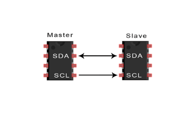 I2C
I2C
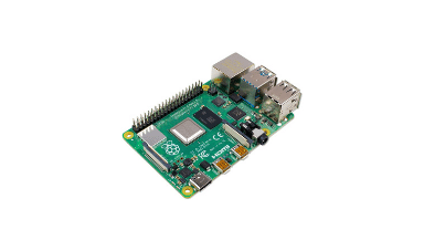 Rasberry Pi
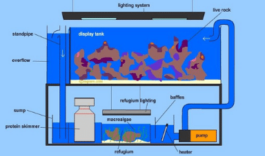 Sump
Sump
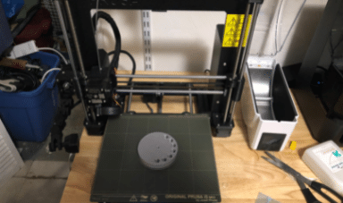
3D Printing
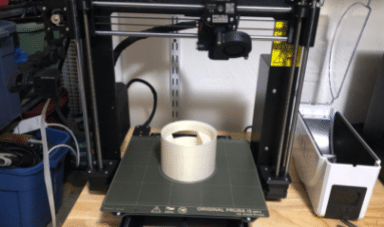
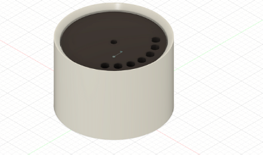
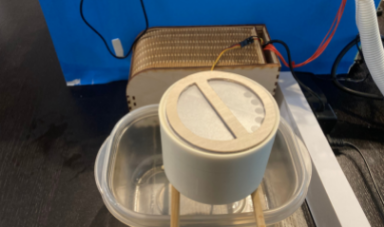
To show 3D and Additive Manufacturing skills I designed and printed the Fish Feeder. I decided to make this in Fusion 360 and even included a joint to be able to line it up properly since the servo can only rotate 180 degrees. I decided to go with a design where one can place the food in a slot for each of seven days of the week and go and so every 24 hours the servo can rotate to the appropriate slot and drop the food and other chemicals or nutrients placed by the user allowing for daily addition of chemicals and food. I desined it in two components a base and a top which allowed me to use the joints to rotate the parts. I also made a third component being a cover which I designed briefly in Fusion and will refocus on later in this project. I then printed both components using my Prusa MK3S with Prusament filament using the reccomended setting by Prusa for their filament.
To show 3D and Additive Manufacturing skills I designed and printed the Fish Feeder. I decided to make this in Fusion 360 and even included a joint to be able to line it up properly since the servo can only rotate 180 degrees. I decided to go with a design where one can place the food in a slot for each of seven days of the week and go and so every 24 hours the servo can rotate to the appropriate slot and drop the food and other chemicals or nutrients placed by the user allowing for daily addition of chemicals and food. I desined it in two components a base and a top which allowed me to use the joints to rotate the parts. I also made a third component being a cover which I designed briefly in Fusion and will refocus on later in this project. I then printed both components using my Prusa MK3S with Prusament filament using the reccomended setting by Prusa for their filament.
 Top Feeder
 Base
Base
 Fusion 360
Cricut and Laser Cutter
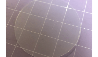
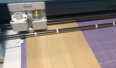
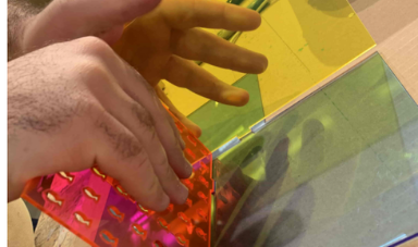
This next part of the project demonstrated 2D and subtractive maufacturing skills. I was originally planning on doing this all on the laser cutter, but due to poor installation and students apparently not being smart enough to turn on the vent when using the laser cutter it broke and so I had to imrpovise for part of this. THe first part I made on the laser cutter was a box using an svg generated from this website here. I then brought it into illustrator to nest it properly and cut it on our epsilon laser cutter with the settings 10 power 100 speed 100 frequency. I then assembled the box and used it to neatly store the excess wiring. Next I used a cricut which to design a lid for the fish feeder. I designed two parts a clear part and a handle. Using the deepcut blade on the cricut I cut some balsa wood to make the handle and clear cutting pad to for the clear part. I then hot glued the two together to make the cover. I had some difficulty cutting the cutting pad with it taking me upwards of 20 cuts in order to actually properly cut it.
This next part of the project demonstrated 2D and subtractive maufacturing skills. I was originally planning on doing this all on the laser cutter, but due to poor installation and students apparently not being smart enough to turn on the vent when using the laser cutter it broke and so I had to imrpovise for part of this. THe first part I made on the laser cutter was a box using an svg generated from this website here. I then brought it into illustrator to nest it properly and cut it on our epsilon laser cutter with the settings 10 power 100 speed 100 frequency. I then assembled the box and used it to neatly store the excess wiring. Next I used a cricut which to design a lid for the fish feeder. I designed two parts a clear part and a handle. Using the deepcut blade on the cricut I cut some balsa wood to make the handle and clear cutting pad to for the clear part. I then hot glued the two together to make the cover. I had some difficulty cutting the cutting pad with it taking me upwards of 20 cuts in order to actually properly cut it.
 Cricut Cover
 Cutting the Wooden Board
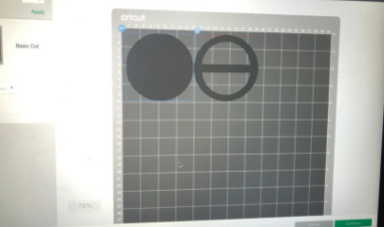 Cricut Design
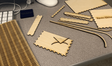 Cut Pieces
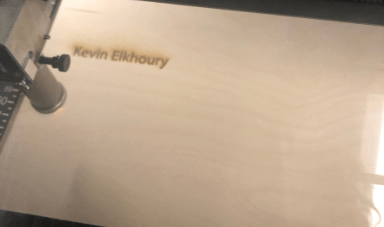 Cutting the Wooden Board
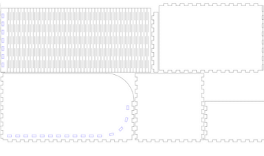 SVG File
PCB Milling and Programming
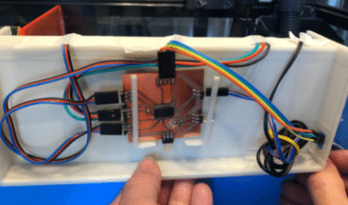
Despite my focus being primarly on the fish feeder up to now due to some mix ups I actually ended up milling and programming the sesor board and John milled and programmed the servo board. I designed the sensor board on KiCad with numerous three pin male headers for vcc ground and data to connect to each one of our sensors. In addition I also added a 4 pin header with ground vcc SDA and SCL to connect to the I2C junction bhox we designed which connects back to the Pi. An I2C bus should only have one pull up resistor or else risks damaging the boards so we put it on the junction box where it felt it belonged. The rest was fairly standard and just like any other week after designing the board, I tossed it into FreeRouter to rout it, brought it over to FlatCam to convert it from a Gerber to an NC file then ran it on my 3018 mill using Candle where I generated a height map first. I then solder all the headers on the board and tested them with a multimeter for everything to be working like intended. The next step was to program the board which I did using the Wire.h library. Each sensor connects to the MC via a single data line which is read with a simple analog read representing a voltage which can be later converted to the unit of interest for the sensor through callibration curves. So for this slave device I gave it an address, simply added a delay in void loop to not clutter the I2C bus and added a receive and receive event. When the slave receives information it will receive a number between 1 and 6 which will be stored in a varibale indicating which sensors information it wants returned. Then for the request event the slave would return the analog read of the sensor variable stored. And that was all the code needed for the slave device. This work was started briefly in testing during my I2C week which can be seen here!
Despite my focus being primarly on the fish feeder up to now due to some mix ups I actually ended up milling and programming the sesor board and John milled and programmed the servo board. I designed the sensor board on KiCad with numerous three pin male headers for vcc ground and data to connect to each one of our sensors. In addition I also added a 4 pin header with ground vcc SDA and SCL to connect to the I2C junction bhox we designed which connects back to the Pi. An I2C bus should only have one pull up resistor or else risks damaging the boards so we put it on the junction box where it felt it belonged. The rest was fairly standard and just like any other week after designing the board, I tossed it into FreeRouter to rout it, brought it over to FlatCam to convert it from a Gerber to an NC file then ran it on my 3018 mill using Candle where I generated a height map first. I then solder all the headers on the board and tested them with a multimeter for everything to be working like intended. The next step was to program the board which I did using the Wire.h library. Each sensor connects to the MC via a single data line which is read with a simple analog read representing a voltage which can be later converted to the unit of interest for the sensor through callibration curves. So for this slave device I gave it an address, simply added a delay in void loop to not clutter the I2C bus and added a receive and receive event. When the slave receives information it will receive a number between 1 and 6 which will be stored in a varibale indicating which sensors information it wants returned. Then for the request event the slave would return the analog read of the sensor variable stored. And that was all the code needed for the slave device. This work was started briefly in testing during my I2C week which can be seen here!
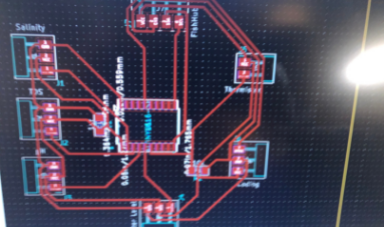 KiCad
KiCad
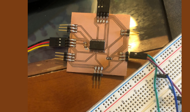 Programming Board
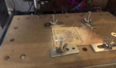 Milling the Board
Other Contributions
This following tasks were mainly completed by John and deserved credit for his contributions here. John was responsible for milling and soldering and programming the junction box board and the servo board. THe junction box was the board we used to connect the servo board and i2c board to via i2c which had a pull up resistor on for SDA and SCL then connected back to the Pi there was no MC on this board. The servo board, simmiliar to the sensor board is another of our hubs for the system and connected to a servo as well as a power outlet having a seperate vcc for the servo with a common ground to not blow the MC and potentially even the Pi due to the servo requiring quit a lot of watts. It's slave code had it turn different degrees to get the proper day to drop the food then back to the zero degree based off of what number is sent to it via I2C (some value between 1 and 7). And finally he designed and printed the sensor box to hold all the sensors and the PCB board, which though had its complications on the first print worked out in the end with a few modifications.
This following tasks were mainly completed by John and deserved credit for his contributions here. John was responsible for milling and soldering and programming the junction box board and the servo board. THe junction box was the board we used to connect the servo board and i2c board to via i2c which had a pull up resistor on for SDA and SCL then connected back to the Pi there was no MC on this board. The servo board, simmiliar to the sensor board is another of our hubs for the system and connected to a servo as well as a power outlet having a seperate vcc for the servo with a common ground to not blow the MC and potentially even the Pi due to the servo requiring quit a lot of watts. It's slave code had it turn different degrees to get the proper day to drop the food then back to the zero degree based off of what number is sent to it via I2C (some value between 1 and 7). And finally he designed and printed the sensor box to hold all the sensors and the PCB board, which though had its complications on the first print worked out in the end with a few modifications.
 Laser Cut Pieces
 Assemble Sump
 Back of Design
Rasberry Pi and Neils Complaints Addressed
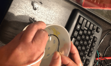
The last part of this project, which was quite a major part was from the Pi. Here is used the Smbus library in Python which I learned previousely about in this week here. Then I also used the same UI maker Tkinter that I previously used in this week here. The first thing that had to be done was make a UI to display all the information which was done easily with Tkinter which I then added a clock to to be able to see the day and time. I realized when making the UI that I will need to update the values every second for the clock and every 30 seconds to all the other values related to the sensors so I made the UI variable in a class so that I could make a new instance of the class when updating all the values which was far simpler then changing the values. Now all the was left was to incorporate the SMBus library and to connect to sensor board slave device and request the information. Of course the information received was a voltage unfortunately from analog read so useless by itself. To fix this I made a two point callibration curve for the pH sensor, for conductivity used an equillibria equation found from the makers of the sensor, for the thermistor I used the Steinhart and Hart Equation, which could easily be converted to TDS then the water level sensor was very easy with it detecting water or not if the reading was above a certain value. Then all that was left to do was add a function to run every 24 hours with an incrementing variable from 1 to 7 which reset at 7 to the slave servo board which worked like a charm. And with that the final project was complete all that was left was for me to put everything on the tank wire it together, and film the video.
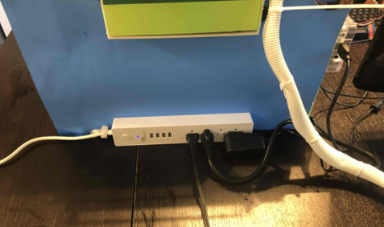
For the video Neil had two complaints the first was a showing PCB board on the back of the tank which was fixed in the photo below, and the second was that we did not show the reading update which I added two photos below showing the reading changing and a video can be seen on John's site. As you can see it says fetching data when in the process of updating the data and this occurs every 30 seconds. In the end our device worked like a charm and we made a fish tank sump and feeder with live readings we did not manage to fit in all the features we were hoping to be we can always add them later with the modular design we established. You can see a run down of the plans before hand answering many questions on the week here!
The last part of this project, which was quite a major part was from the Pi. Here is used the Smbus library in Python which I learned previousely about in this week here. Then I also used the same UI maker Tkinter that I previously used in this week here. The first thing that had to be done was make a UI to display all the information which was done easily with Tkinter which I then added a clock to to be able to see the day and time. I realized when making the UI that I will need to update the values every second for the clock and every 30 seconds to all the other values related to the sensors so I made the UI variable in a class so that I could make a new instance of the class when updating all the values which was far simpler then changing the values. Now all the was left was to incorporate the SMBus library and to connect to sensor board slave device and request the information. Of course the information received was a voltage unfortunately from analog read so useless by itself. To fix this I made a two point callibration curve for the pH sensor, for conductivity used an equillibria equation found from the makers of the sensor, for the thermistor I used the Steinhart and Hart Equation, which could easily be converted to TDS then the water level sensor was very easy with it detecting water or not if the reading was above a certain value. Then all that was left to do was add a function to run every 24 hours with an incrementing variable from 1 to 7 which reset at 7 to the slave servo board which worked like a charm. And with that the final project was complete all that was left was for me to put everything on the tank wire it together, and film the video.
For the video Neil had two complaints the first was a showing PCB board on the back of the tank which was fixed in the photo below, and the second was that we did not show the reading update which I added two photos below showing the reading changing and a video can be seen on John's site. As you can see it says fetching data when in the process of updating the data and this occurs every 30 seconds. In the end our device worked like a charm and we made a fish tank sump and feeder with live readings we did not manage to fit in all the features we were hoping to be we can always add them later with the modular design we established. You can see a run down of the plans before hand answering many questions on the week here!
 Testing Sensor
 Hooking up Sensor Board
 Callibrating Sensor
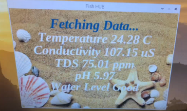 Data Screen Pre Change
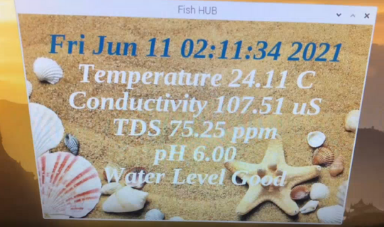 Data Screen Post Change
 Back with No PCB
Click Here for the BOM for this project!
Click Here to Download all the files from these projects!

This work is licensed under a Creative Commons Attribution-NoDerivatives 4.0 International License.