network and Communication
Types of Communication Protocols
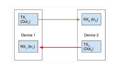
Communication protocols are ways for different devices to communicate with one another with more complexity than just using a digital signal. There are various types of communication protocols each with their own set of advantages and disadvantages. Starting with UART which stands for universal asynchronous receive and transmit. The way it works is quite simple with their being two lives an Rx and Tx with Tx connecting to Rx and vice versa. This allows the sending of data between two devices as bits. However it is overall relatively slow. This is improved with SPI where a master device communicates to multiple slave devices using various lines: SS (slave select to choose which slave to talk to), SCL (Clock to set the clock speed), MISO (Master in slave out for the slave to communicate with the master device), and MOSI (Master out slave in for the master to communicate with the slave device). This method is fart faster than UART and allows for better communication between multiple microcontrollers. However does requirte a lot of wires to be used. Finally the most complex protocol I2C works with just two lines SDA amd SCL. SCL sets the clock speed, and SDA contains the data sent in sort of packets each with an address, so if each slave only reads data from its own packet there can be as many slaves and masters as one wants using I2C.
Communication protocols are ways for different devices to communicate with one another with more complexity than just using a digital signal. There are various types of communication protocols each with their own set of advantages and disadvantages. Starting with UART which stands for universal asynchronous receive and transmit. The way it works is quite simple with their being two lives an Rx and Tx with Tx connecting to Rx and vice versa. This allows the sending of data between two devices as bits. However it is overall relatively slow. This is improved with SPI where a master device communicates to multiple slave devices using various lines: SS (slave select to choose which slave to talk to), SCL (Clock to set the clock speed), MISO (Master in slave out for the slave to communicate with the master device), and MOSI (Master out slave in for the master to communicate with the slave device). This method is fart faster than UART and allows for better communication between multiple microcontrollers. However does requirte a lot of wires to be used. Finally the most complex protocol I2C works with just two lines SDA amd SCL. SCL sets the clock speed, and SDA contains the data sent in sort of packets each with an address, so if each slave only reads data from its own packet there can be as many slaves and masters as one wants using I2C.
 UART
UART
.png) SPI
SPI
.png) I2C
I2C
Group Portion
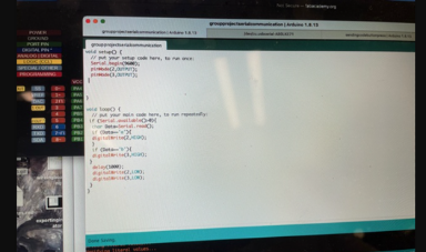
For the group project this week we used two old board lying around each with serial ports available and connected them to one another Rx to Tx and Tx to Rx. One of the boards had a couple of buttons and the other board a couple of LEDs. We made a simple code where board A (the one with the buttons) would send a message using Serial.print to Board B (The one with Two LEDs and turn) that would send over a character a or b which would make one of the two LEDs turn on. From here we just made a few modifications to the code where we make a game of quick draw where a LED that was on board A would turn on then the first player to press the button would make there LED on the other board turn on. Fun simple game in just a few lines of code.
For the group project this week we used two old board lying around each with serial ports available and connected them to one another Rx to Tx and Tx to Rx. One of the boards had a couple of buttons and the other board a couple of LEDs. We made a simple code where board A (the one with the buttons) would send a message using Serial.print to Board B (The one with Two LEDs and turn) that would send over a character a or b which would make one of the two LEDs turn on. From here we just made a few modifications to the code where we make a game of quick draw where a LED that was on board A would turn on then the first player to press the button would make there LED on the other board turn on. Fun simple game in just a few lines of code.
.png) Board A Program
Board A Program
 Board B Program
.png) Connections
Connections
Designing and Fabricating
This section is getting very repetitive. Nothing inciteful ever happens here since I stopped using the Roland and just use my mill that costs a fraction of the cost. For this board I designed it so that it had two microcontrollers and an FTDI port so that Tx of FTDI went to MC, Tx of MC A when to MC B and Tx of MC B went back to FTDI. This allowed me to communicate via serial communication over the three sources. I designed it in KiCAD as usual using attiny 1616 (found some lying around), and assigned the footprints, brought it to PCB mode, used an auto router, exported as GERBER to FlatCAM, brought to Candle, generated a heightmap, and milled the board with 1/64 ball nose endmill. Nothing special happened, it worked like a charm on the first try like it usually does I cover this section in more detail in previous weeks but it is literaly copy and past at this point this section is only of interest if the mill your using is awful and you need to redo you boards like three times. Once milled I soldered it with a heat gun and solder paste, as usual, nothing new here.
This section is getting very repetitive. Nothing inciteful ever happens here since I stopped using the Roland and just use my mill that costs a fraction of the cost. For this board I designed it so that it had two microcontrollers and an FTDI port so that Tx of FTDI went to MC, Tx of MC A when to MC B and Tx of MC B went back to FTDI. This allowed me to communicate via serial communication over the three sources. I designed it in KiCAD as usual using attiny 1616 (found some lying around), and assigned the footprints, brought it to PCB mode, used an auto router, exported as GERBER to FlatCAM, brought to Candle, generated a heightmap, and milled the board with 1/64 ball nose endmill. Nothing special happened, it worked like a charm on the first try like it usually does I cover this section in more detail in previous weeks but it is literaly copy and past at this point this section is only of interest if the mill your using is awful and you need to redo you boards like three times. Once milled I soldered it with a heat gun and solder paste, as usual, nothing new here.
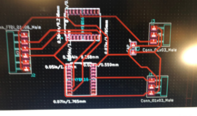 KiCAD PCB View
.png) Milled Board
Milled Board
.png) Candle heightmap
Candle heightmap
Programming
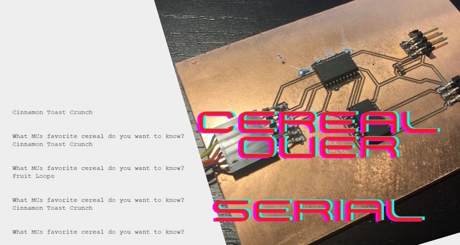
For this week my friend who does not know much about electornics or computers was joking with me about Serial communication comparing it to cereal the food, so I decided to with it. How this program work is a prompt will appear to the user asking which microcontrollers favorite cerarl would it like to know. Then they can type either A or B. If they type A a message is sent to the first microcontroller who will read the message and respond with "Fruit Loops" sending the message to B who will then send it back to the computer. If B was sent originally, the message would still be first sent to A who would ignore the message and relay it to B who would respond "Cinnamon Toast Crunch". I did however run into a problem where the message being sent was to slow since Serial is slow and only send a character at a time resulting in weird single character answers being sent one after another. Instead to fix this I created a buffer that would keep getting the word until it read the character \n which indicates the end of the string.
For this week my friend who does not know much about electornics or computers was joking with me about Serial communication comparing it to cereal the food, so I decided to with it. How this program work is a prompt will appear to the user asking which microcontrollers favorite cerarl would it like to know. Then they can type either A or B. If they type A a message is sent to the first microcontroller who will read the message and respond with "Fruit Loops" sending the message to B who will then send it back to the computer. If B was sent originally, the message would still be first sent to A who would ignore the message and relay it to B who would respond "Cinnamon Toast Crunch". I did however run into a problem where the message being sent was to slow since Serial is slow and only send a character at a time resulting in weird single character answers being sent one after another. Instead to fix this I created a buffer that would keep getting the word until it read the character \n which indicates the end of the string.
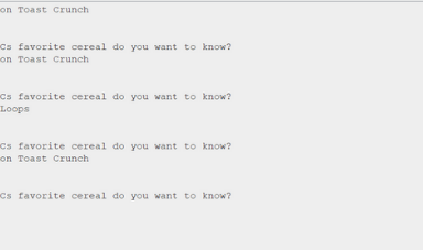 Working Serial Output
.png) Board B Program
Board B Program
.png) Board A Program
Board A Program
Second Communication Board
I made a second pair of boards for this week as well. These pair of boards were tests for the final project and are two boards that connect of I2C. The boards were designed in KiCAD with the same milling process as every other week using an Attiny 1616 and 3216 (I am scavenging stuff). The communication method is I2C which can work with multiple masters and multiple slave devices. The protocol works with each slave getting an address and messages being sent in bit format to the slave address, so all other devices would ignore messages that are not for their address. This is perhaps the best communications protocol connecting with just two wires clock (SCL) and data (SDA) simmilar to Serial but unlike serial is far faster and works with multple devices.
I took my boards from input anmd output week which happened to have i2c pins and connected them with a Rasberry Pi to have easy access to I2C using the library SMBUS. The Rasberry Pi has multiple I2C lines with one of them reserved to only work with shields and other devices. I programmed both of the microcontrollers boards with easy codes in Arduino using the Wire library that when they receive data they will respond with their name I gave them Steve and Frank. Then on the rasberry pi I enabled I2C in the config menu and then using the library SMBUS I wrote a program in python that would request information from address 7 and 8 (my two boards) where it will get the data and print the name.
I ran into some small problems with getting the data since I was getting just one byte so I switched commands in python to the read block command and created a buffer to keep reading till the value was 255 which represents the pull up resistor meaning no more bits are being sent.
 Programming Board
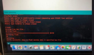 Board Programmed
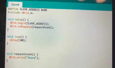 Slave Program
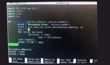 Programming Master Device
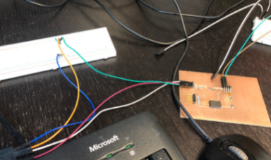
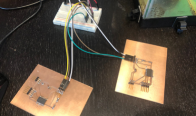 Hooking up Slaves and Master Device
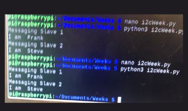 Working Output
Click Here to Download all the files from these projects!