Final
Project
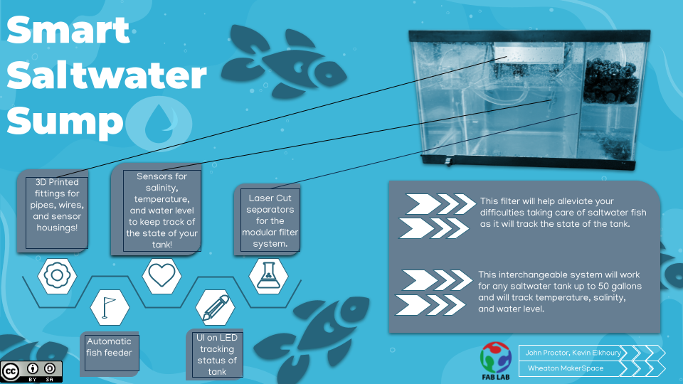
Making a Smart Sump Filter for a Saltwater Tank
Credits:This presentation template was created by Slidesgo, including icons by Flaticon, infographics & images by Freepik.
A Big Change
Due to a conversation that we had with one of our instructors we lost confidence in our inital project, a card scanner for the makerspace. Since then we've lateralled to building a sump filter for a saltwater fish tank. A sump filter is a very effective multichamber filter. Water is removed from the actual fishtank via a gravity overfil tank. The water is then run through several different filters before being pumped back into the tank. Sumps are useful because of the interchangabilty of different filters that can be in the sump it's self the sump can also contain other useful things like an aquarium heater.
Heating Board for Sump THAT ENDED UP NOT BEING USED
This weekend I worked on designing a circuit board that can take readings from a temperature readings from a sensor and then control the wether a heater is turned on or not. The heat sensor takes a power and ground cable, and another cable to return the data, so I have a three pronged header on the board. The heater however is going to need to be controlled by a mosfet, which I have alot of experience with due to some trouble that we had in the group machining week. A mosfet works like a gate where depending on the signal being sent to it, it will decide wether it is open or closed. The important part of working with these however is using a diode. If a diode is not branching from the source to the drain then inductance can cause you to blow up mosfets.
The Stuff I did!
So the stuff I did can be broken down into a couple of different categories but I'll give the highlights in this section. For one I designed an acrylic separation system that would ensure that there are different sections in the sump, and proper water flow. I also designed the housing for the sensor board hub, which was the place that housed all of the boards related to the various sensors. In addition to that, I wrote all of the code for the servo, which is what was controlling the fish feeder attachment that we added. I also did most of the work in getting the thermistor to work, which consisted of the code to get temperature data from it, as well as the tedious task of finding the actual constants of the sensor. I also designed the slide that Kevin and I used with help of a friend of mine, Alayna Uniacke.
If I'm going to be honest which I like to be I would also mention that the stuff that I did, and the stuff that Kevin did while done, by one person or the other was done with communication between the two of us, in order to ensure that systems would work together properly and to ensure that each of us actually stayed on track.
I'm also going to mention here that in regards to keeping on track with a timetable... we did not do a very good job at that. On a semester-wide note, we did not have a solid plan, it was Kevin's senior year, and I was busy with just the regular weekly assignments, so I didn't put enough thought into the final project until it was too late. In regards to a crunch time schedule, we did slightly better. We still didn't do good, but I feel like we really had a finished project by the time that we had to present which is something that I am proud of. Yet getting to that point over the course of the last week and a half on campus, was to but lightly hell. There were many late nights caused not only by my own busyness but also by the anxiety of not having a solid plan. Now that that is said I can get onto talking about the processes.
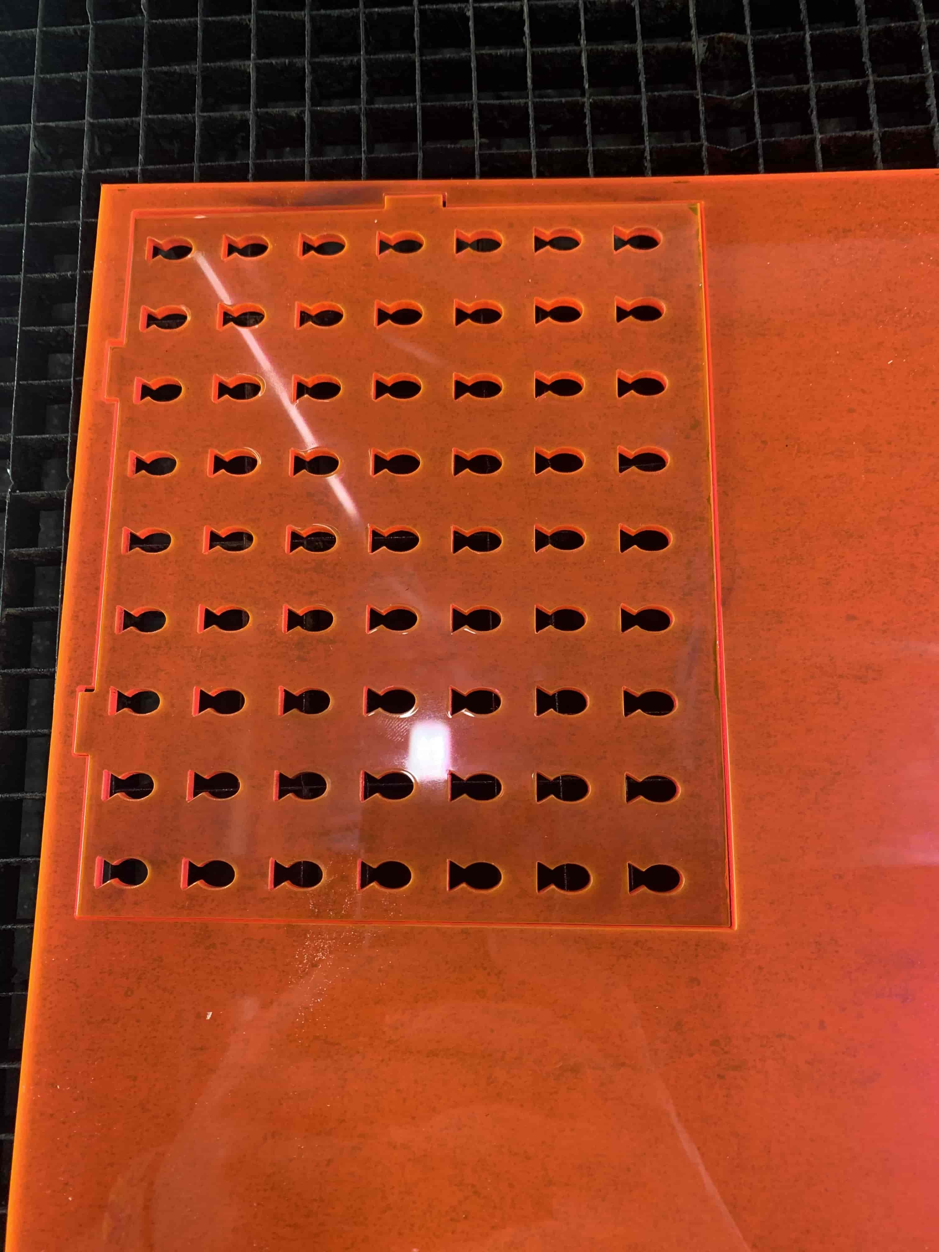
Laser Cutting
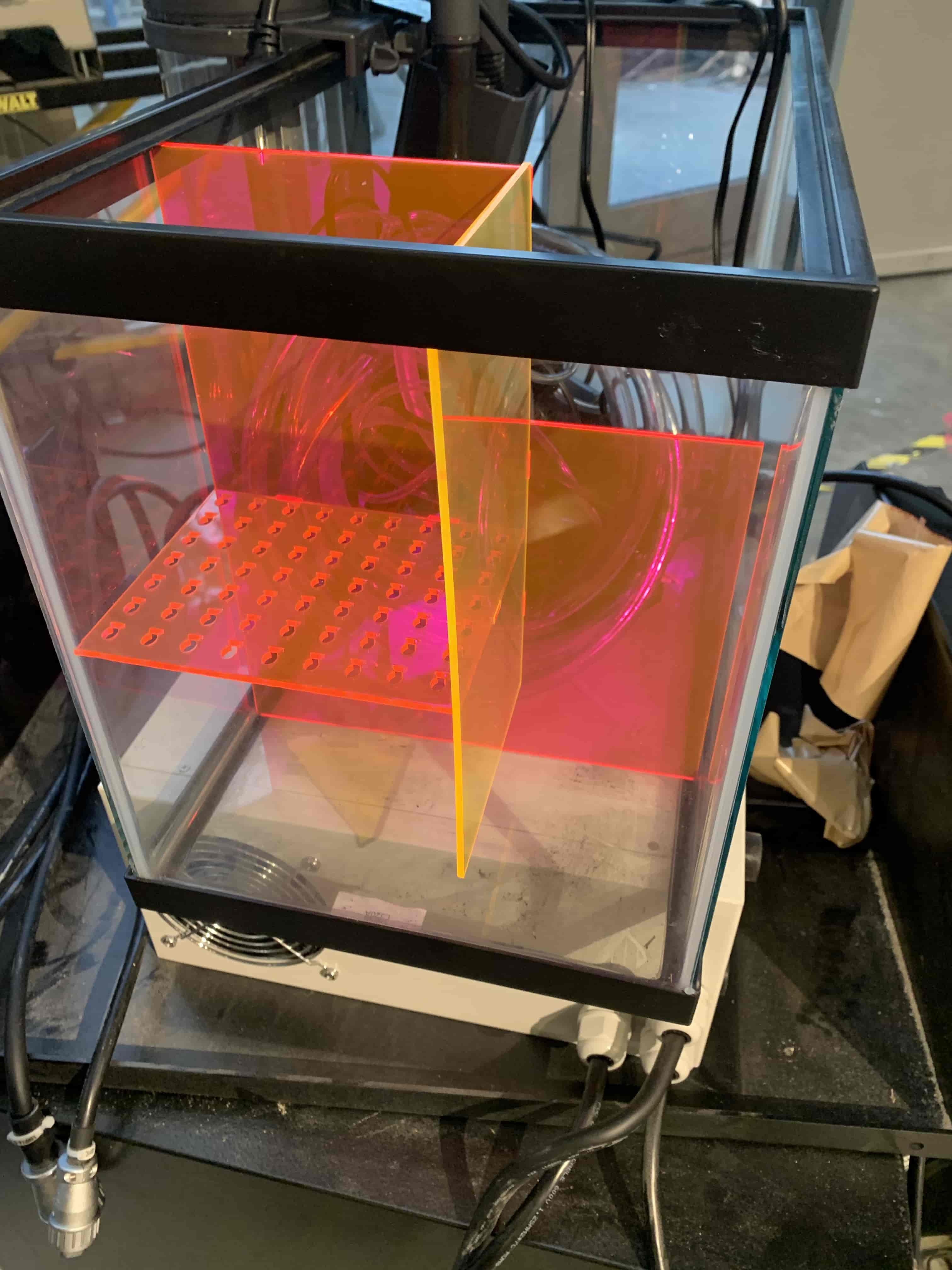
We decided very early on with this project that we would not be making the whole tank of the sump. We didn't feel confident that we could make it sturdy enough to be able to hold water. It was also a concern with logistics given the time that we had to work with. So in order to get a tank for the sump, we went to PetSmart and bought a 10-gallon fish tank. Now a sump filter is effective because the way that water flows through it allows for the water to go through several different types of filtration while fostering the growth of helpful nitrifying bacteria. Usually, these different sections are led into one another simply through gravity flow, to ensure that there are certain areas of more stagnant water.
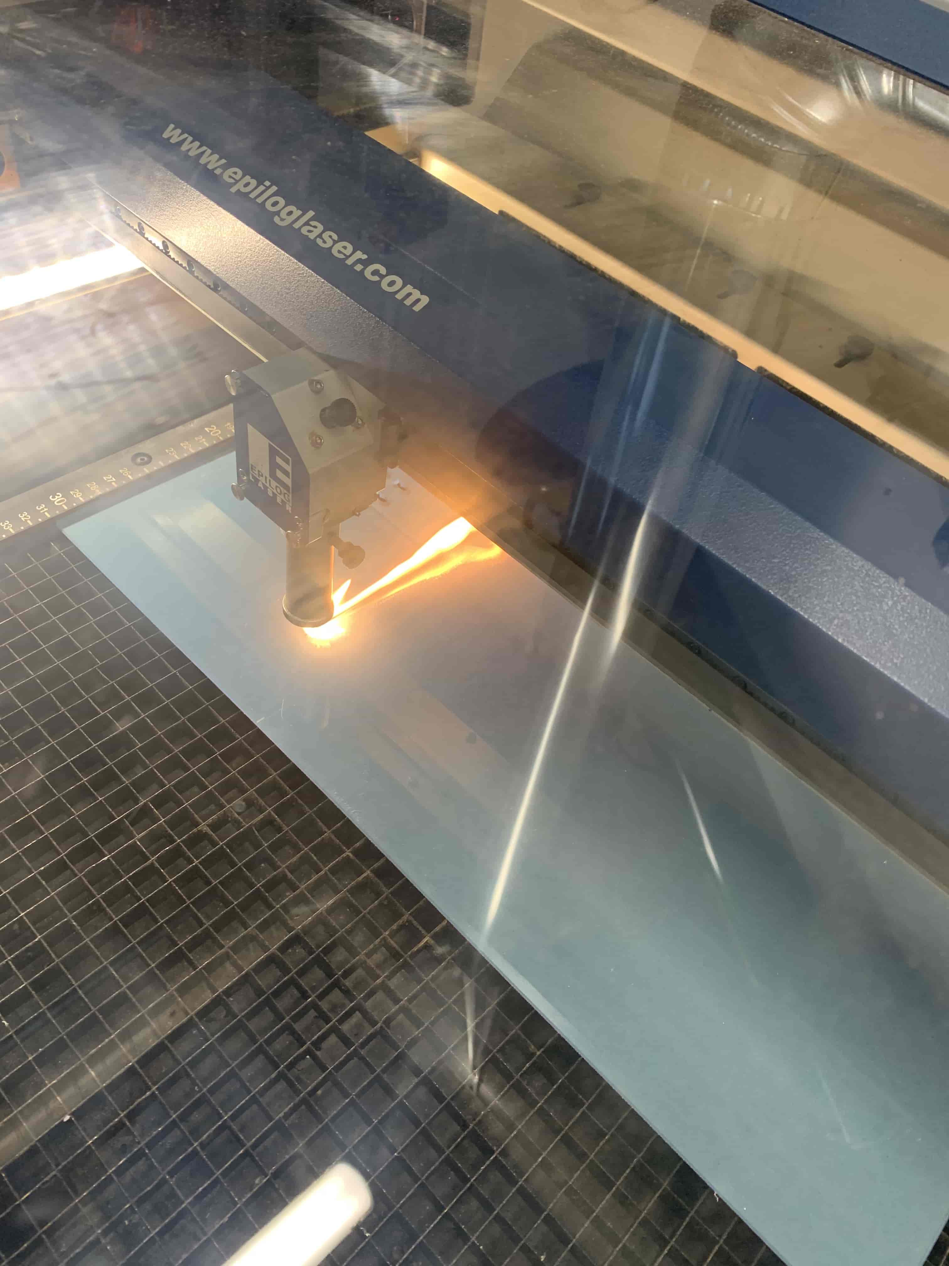
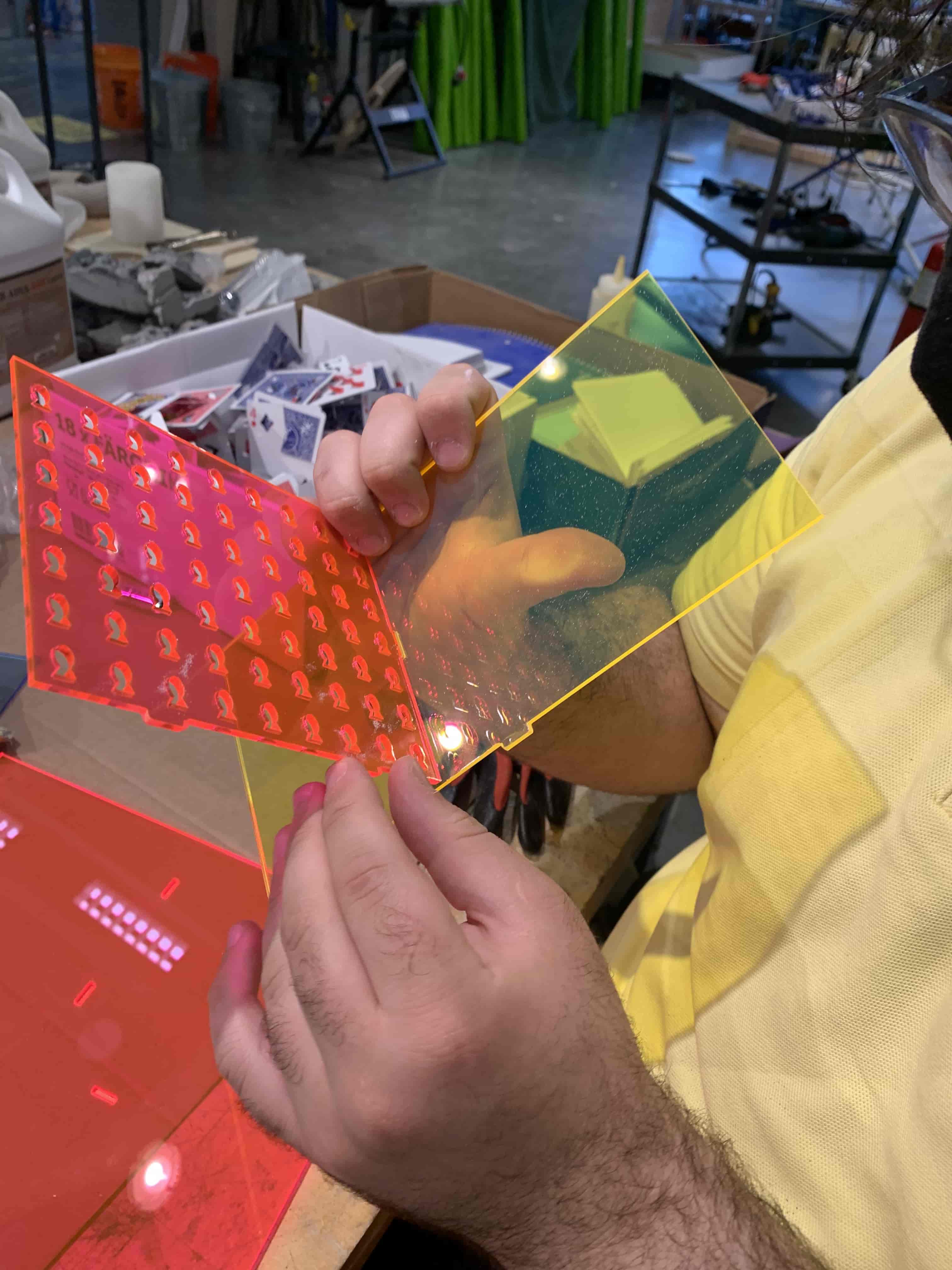
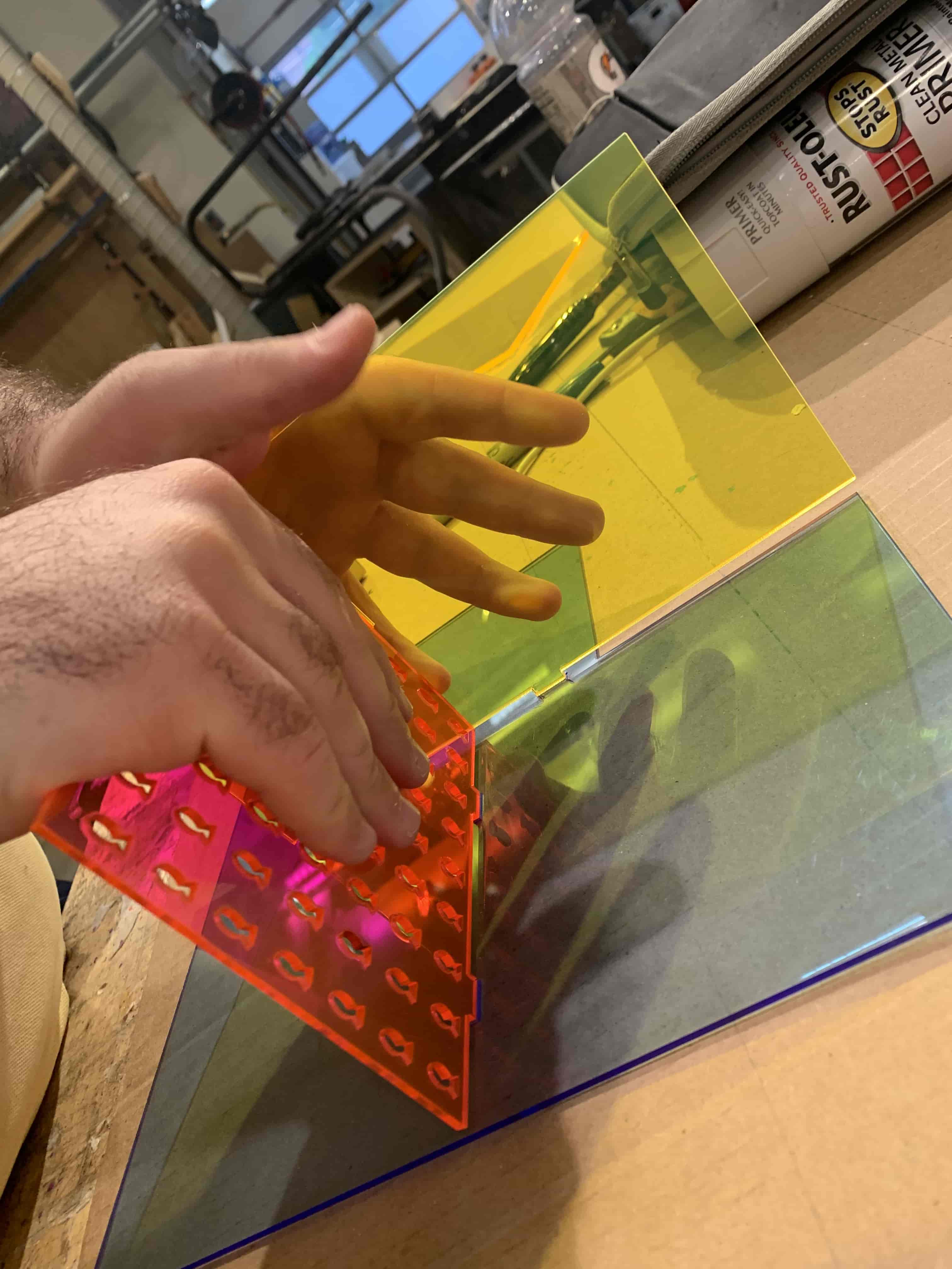
To create these different layers we needed to have inserted into the tank. We felt the best material to do this with would be acrylic as it is something we had plenty of, and it can be cut to specifications with the laser cutter, we also thought it would look cool.
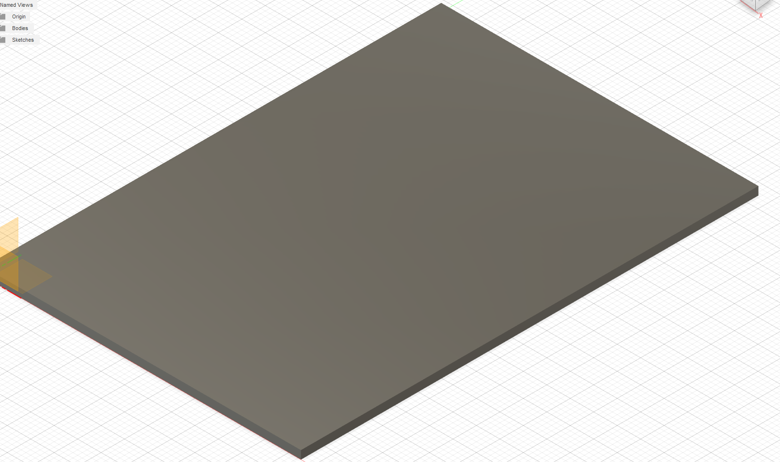
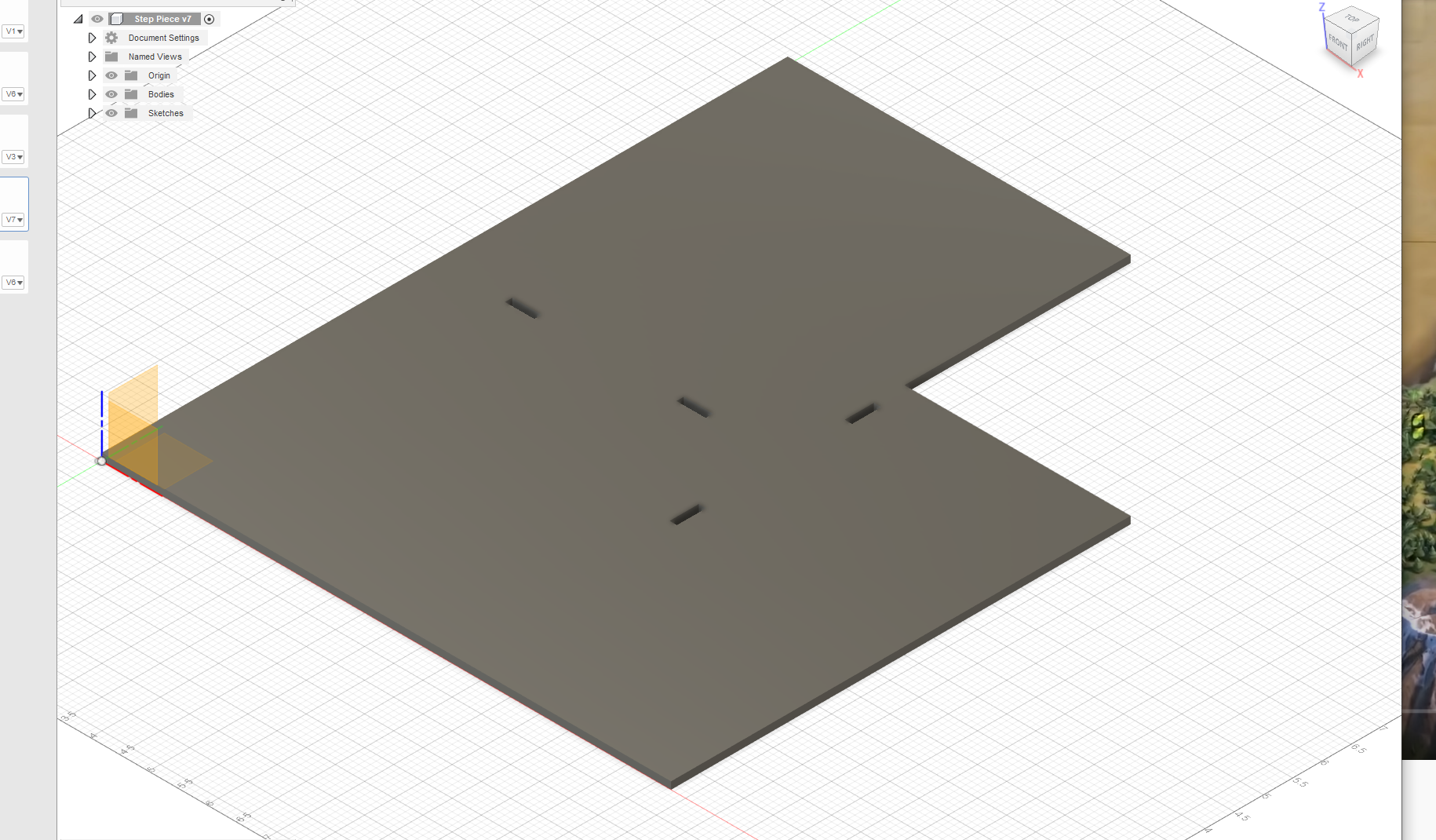
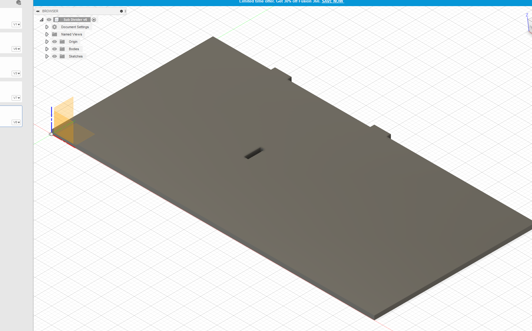
To make the housing I created several different sheets in Fusion 360 so that I could maneuver the model and make sure that the different tabs could fit together properly. This went really rather smoothly. Having the ability to move things in 3D space, and make measurements made this so much easier than if I tried to do this in Illustrator which I considered using initially.
With the design made the laser cutting went very smoothly, all the cuts went through properly, and I didn't break the machine which is a pretty nice bar to clear.
I did have some problems when I tried to assemble the different pieces. For the most part, the pieces went together very smoothly, but there was one piece that ended up breaking, and I needed to cut it out again since I didn't want to ruin the integrity of the whole piece.
All things told this piece ended up coming together relatively easily and I think it ended up looking even cooler than I thought it would because the color of the pieces ended up being more vibrant than I thought it would be.
3D Printing
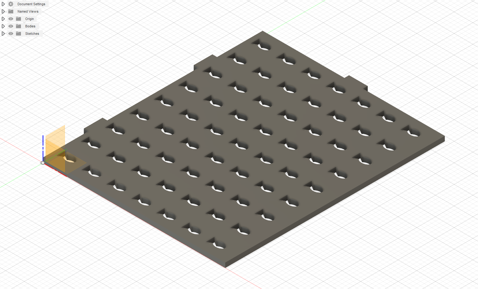
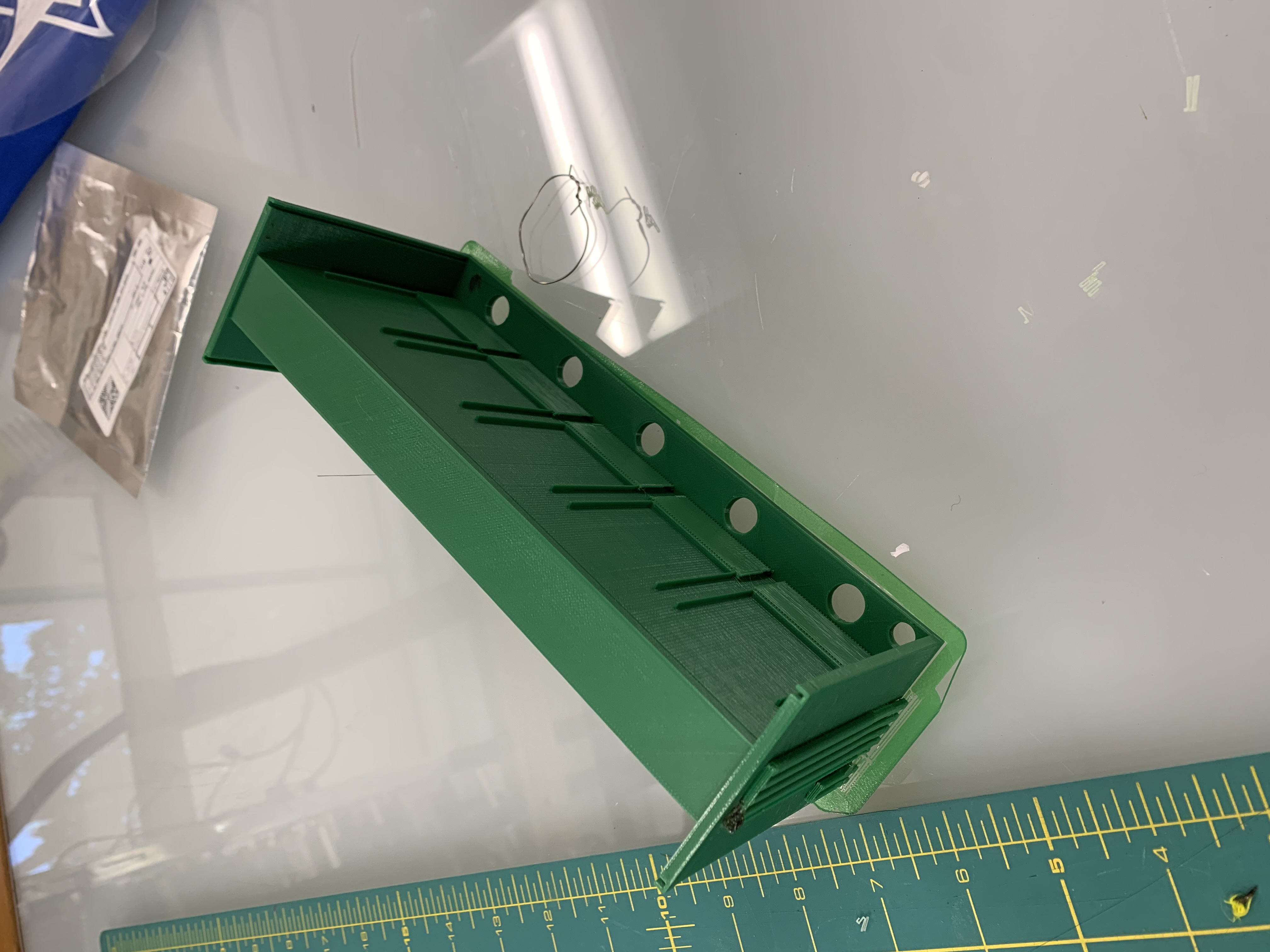
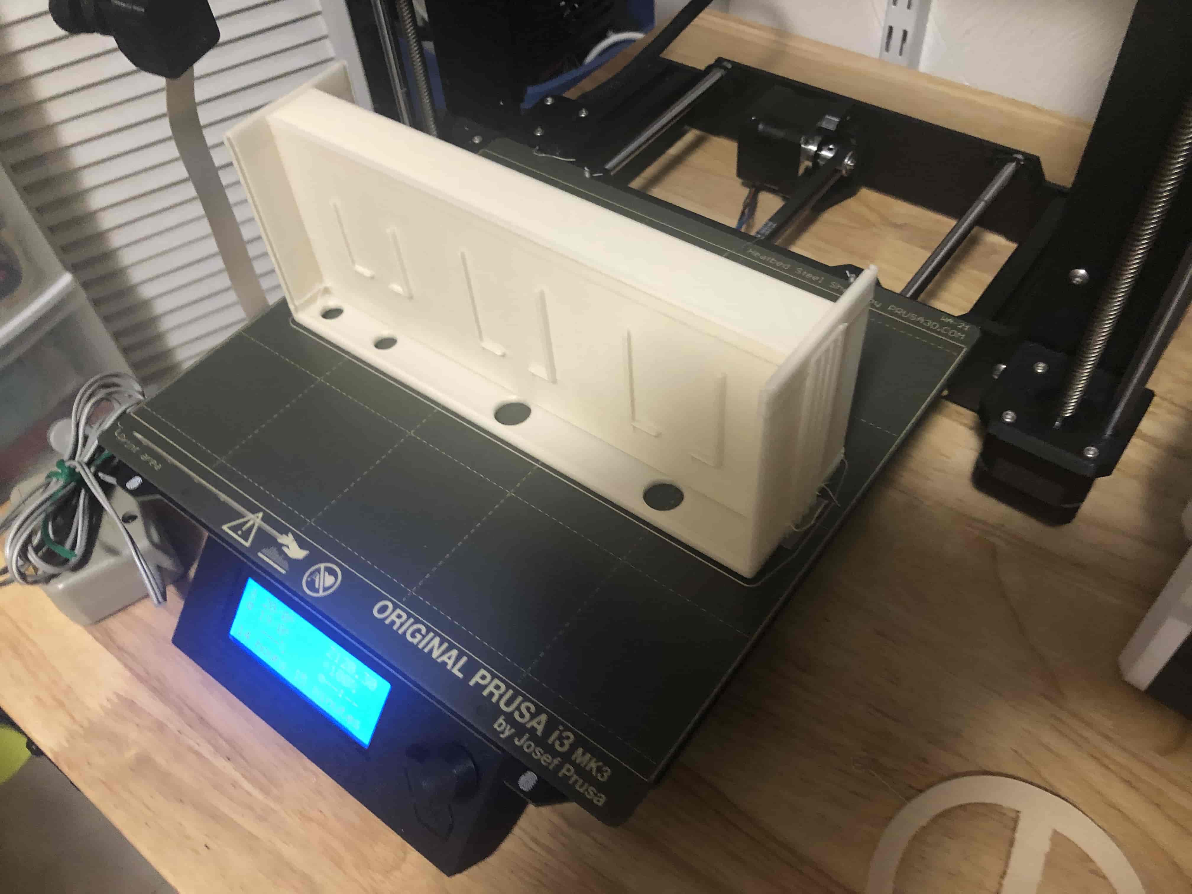
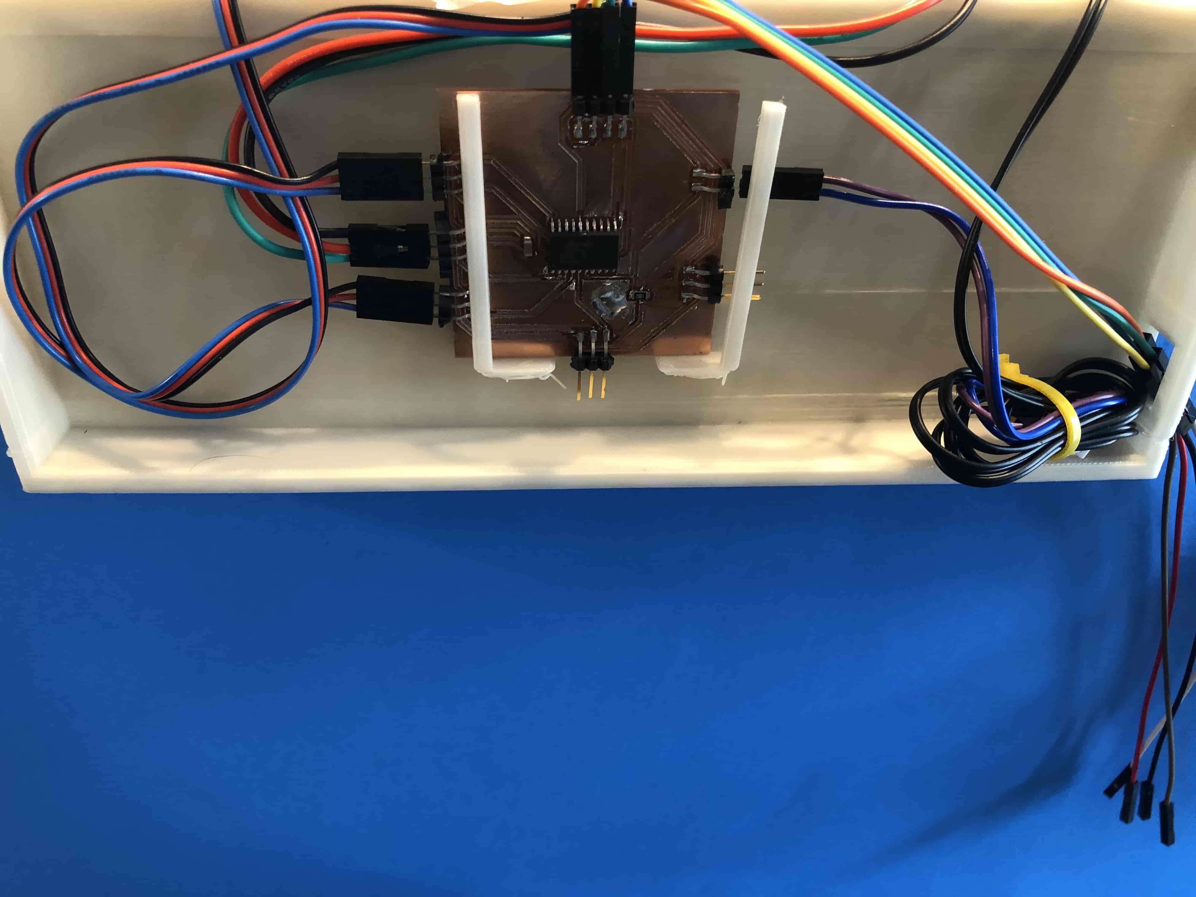
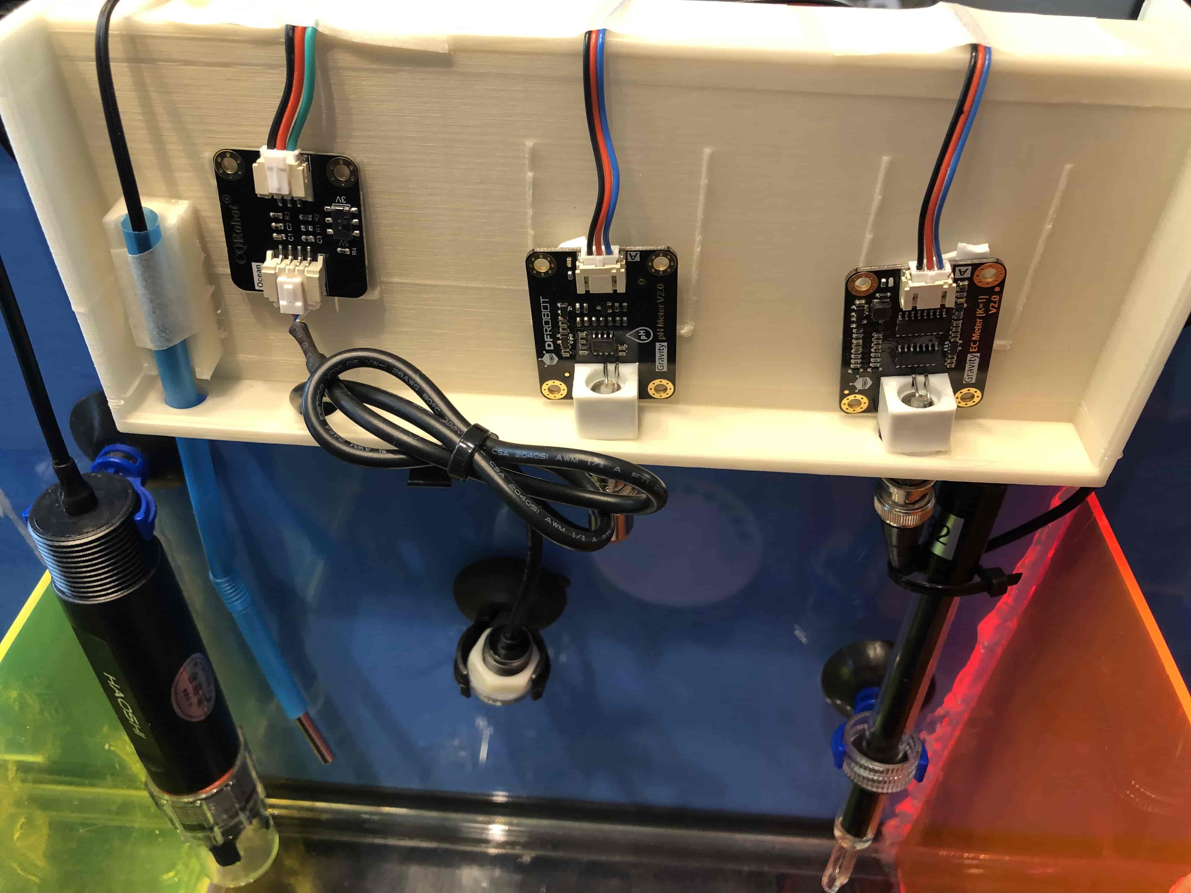
For this part of the project, we knew that we would have a ton of boards since the different sensors that we got came with their own tiny boards. These tiny boards from what we can tell just keep some basic calibration info on them that allow you to calibrate the boards once, and then use them consistently for a while. For as good as their tiny boards are they did lead to problems when we needed to have a properly closed device. However, I came up with a solution to this problem that is an enclosure that can latch onto the side of the tank and hold all of these tiny boards, and our own larger board that was a junction for all of these boards, and sent off the data to a raspberry pi where we processed the information and displayed them on a UI that is updated every 30 seconds. That is why in our initial video for the project we didn't actually show the screen changing.
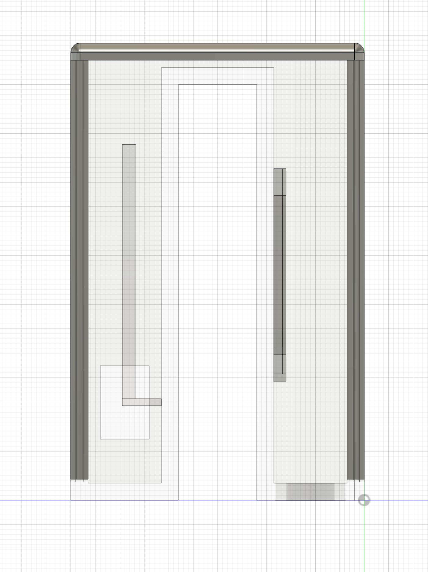
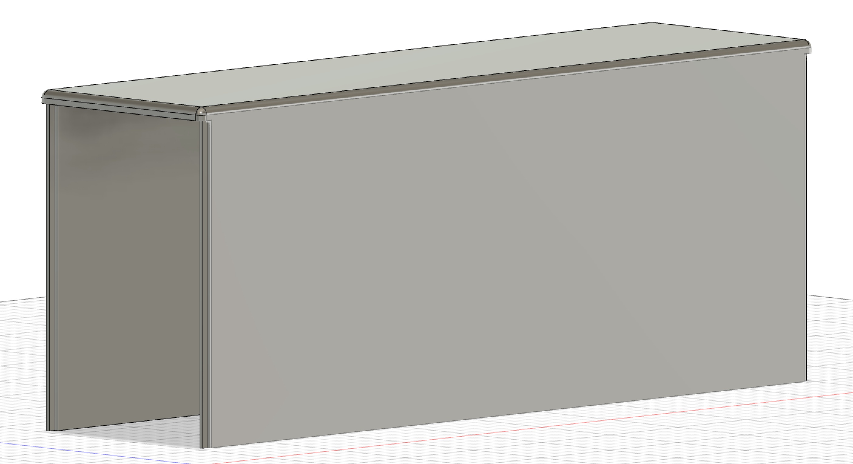
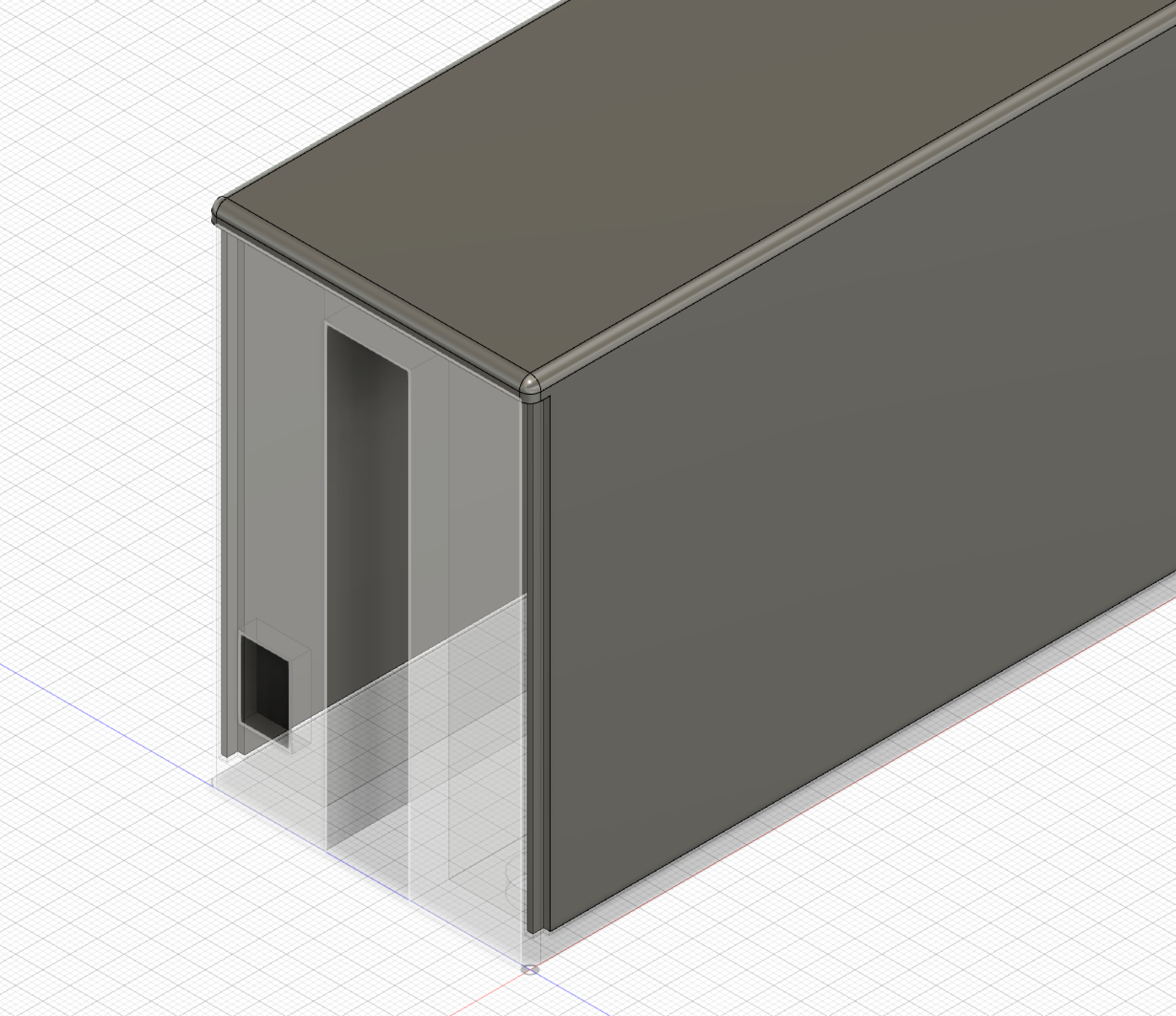
I made the design for this housing in Fusion 360 as two seperate components. One was the bottom of the structure which was a U-shape that fit over the edge of the tank, while the other is a lid that slides into a groove in the box. The bottom portion of the design also has places made on it to slot in the various chips so that they are held and housed properly, as well as several holes in the bottom for wires to feed out of. The design wasn't to difficult to make the bottom portion consisted alot of making squares the extruding them just to cut a portion of the extrusion. The top was a little tricky for me because this is the first thing that I've 3D printed that had a lid that slid onto a base. It still wasn't too bad, and I think that the final piece looks really nice, and everything fits nicely.
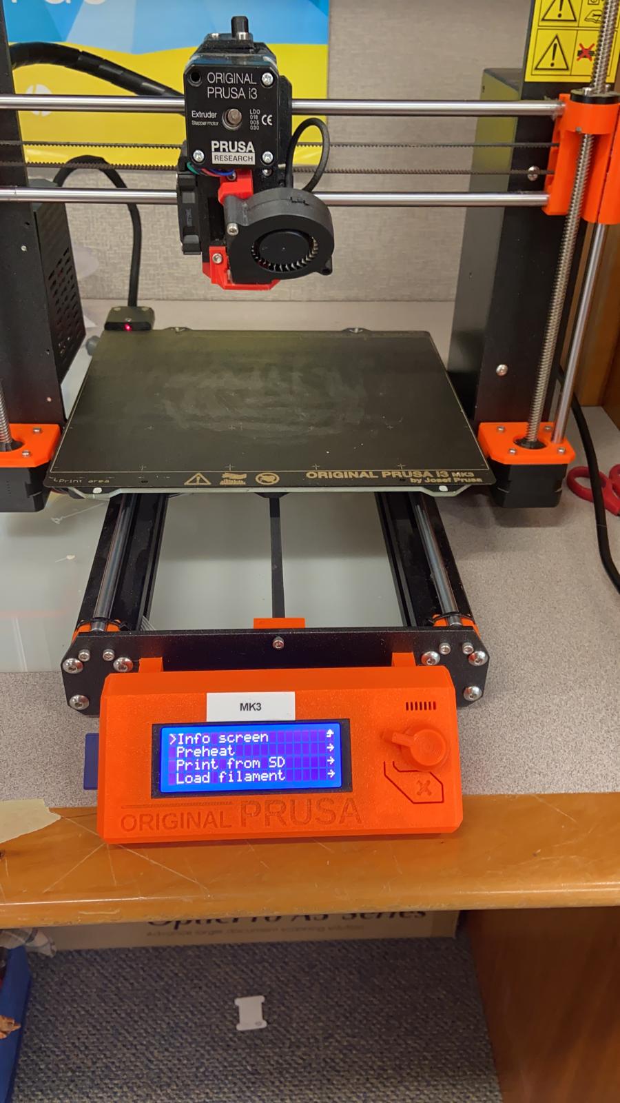
I did run into a couple of problems while printing since the 3D printer that I used was used back to back to back for 48-72 hours and it wasn't super well calibrated to begin with. I am lucky that the trouble never caused a print failure outside my first 30 minutes near the machine. I did need to print the bottom piece of this design twice since on the original the holes on the bottom were to small, and the wire wouldn't feed through properly. When I went to reprint I did find a very fun mistake I had made that being that the original design wasn't saved so really I had to design the whole thing twice the second time was much faster than the first which was nice. However once the second print was done everything fit togehter nicely, and held all the boards like it was supposed to.
Board Milling and Coding
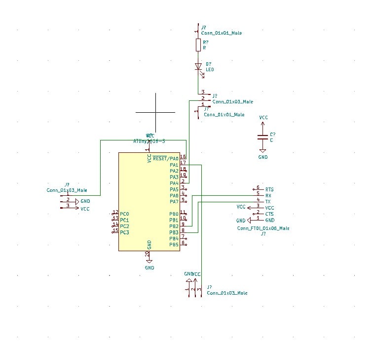
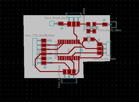
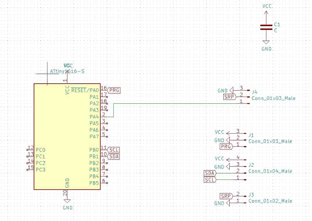
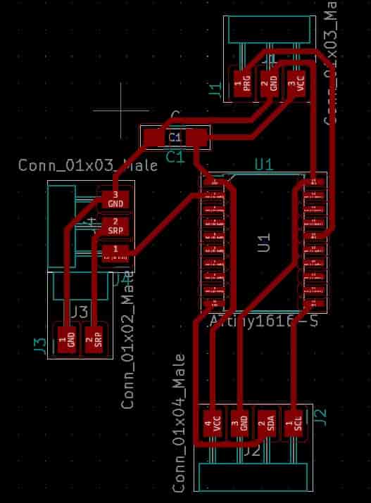
The board that I was in charge of making was the board that controled the servo. The servo was used in Kevin's automatic fish feeder. On this board there were programming pins, I2C pins, servo pins, pins for a seperate power supply, a attiny1616, and a capacitor. I think there are two things on this board that are worth going into, one being the I2C connector, and the other being the alternate power supply. The alternate power supply needed to be used because the servo required more power to move then the board could put out. The alternate power supply was this five volt power cable that Kevin and I had found, and then modified to make it easier to actually atatch to the board. Now the I2C pins aren't to complicated in themselves. Since I2C is done over four pins. One pin is for power another for ground, one for a clock, and one more for data transfer. However I think it's worth mentioning why we ended up choosing I2C over other forms of communication because it fit all of our needs. We could easily structure the system having one master device and several slave devices, and the distance that I2C can work at isn't a problem because this whole apparatus should exist around the fishtank.
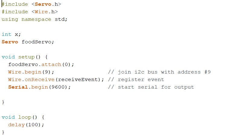
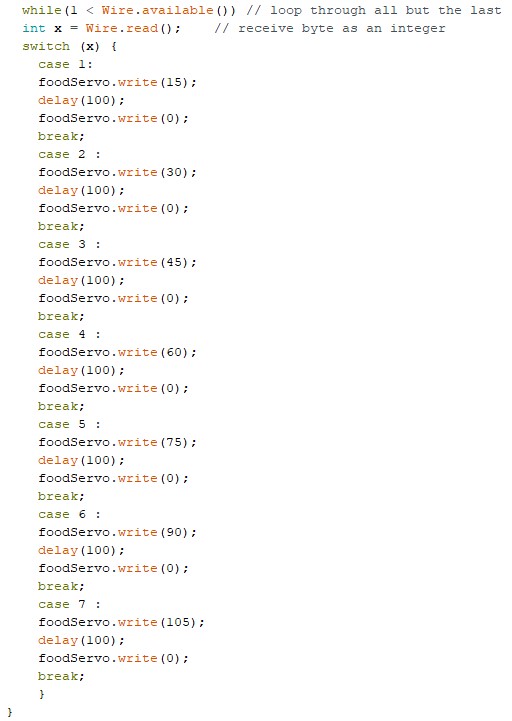
I unfortunately don't have alot to say about coding the board because there really wasn't alot to it. I will show you the code, really most of the work is just using the right libraries so that you can use I2C and the servo, so if you try this don't forget that but otherwise I believe in you. Oh if you want to read about some work I did for the Themistor you can read about how I didn't do it for THIS but like all of the things I say I didn't do there I did do for the themistor for this project!
Bill of Material
Hi I have even less to say here I'm just going to link the excel sheet that I made for a previous week. JUST CLICK HERE
Project Developtment
Hi I did a whole page on this. You can click here to read it!
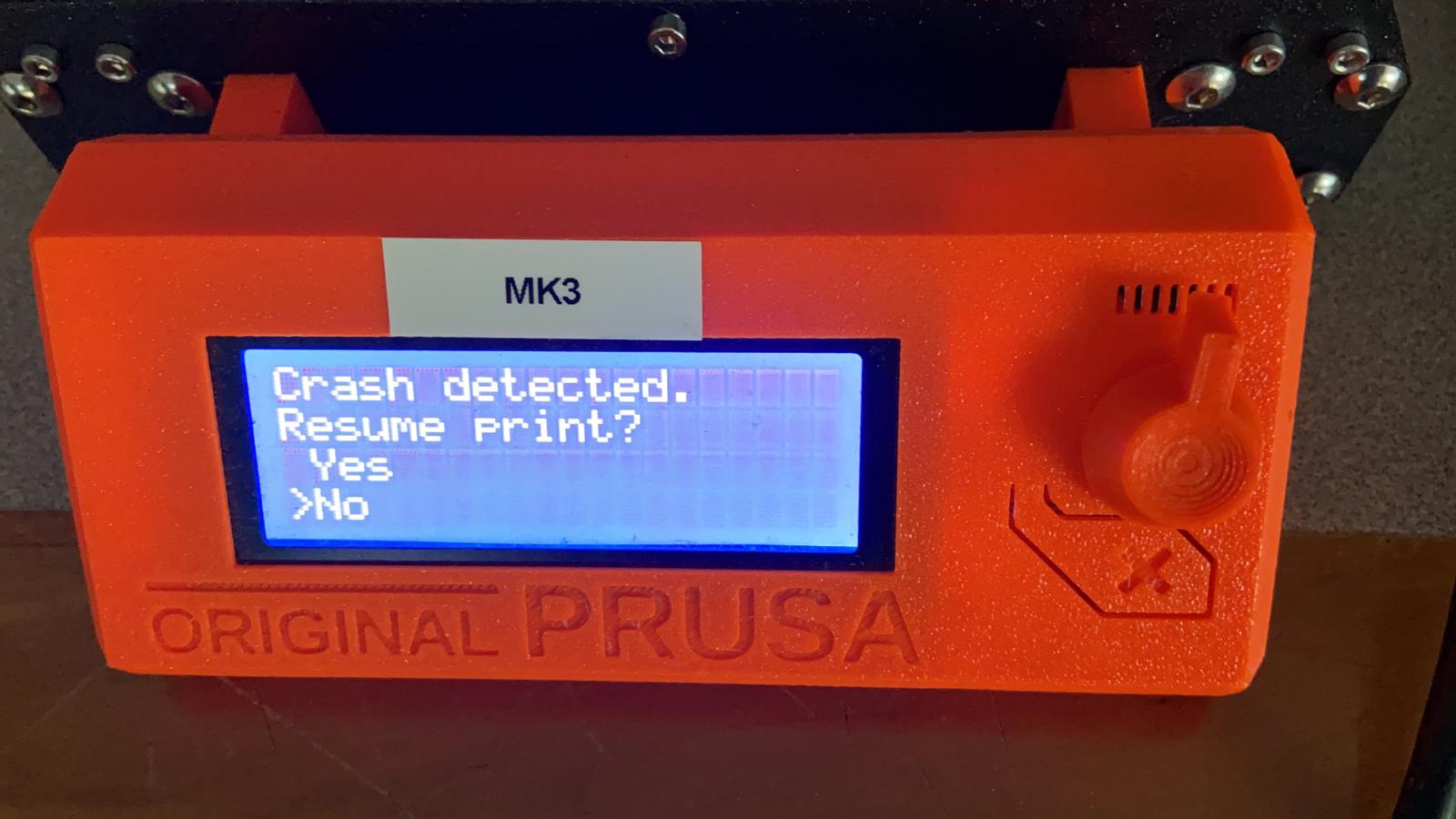
On the subject of Neil's Problems
Hi, so I really really don't want to go through and edit that video I made because it took so long like honestly 5-6 hours which is just stupid, but looking at that now just makes me sad. So what I'm going to be doing is just showing the video below of the UI changing.
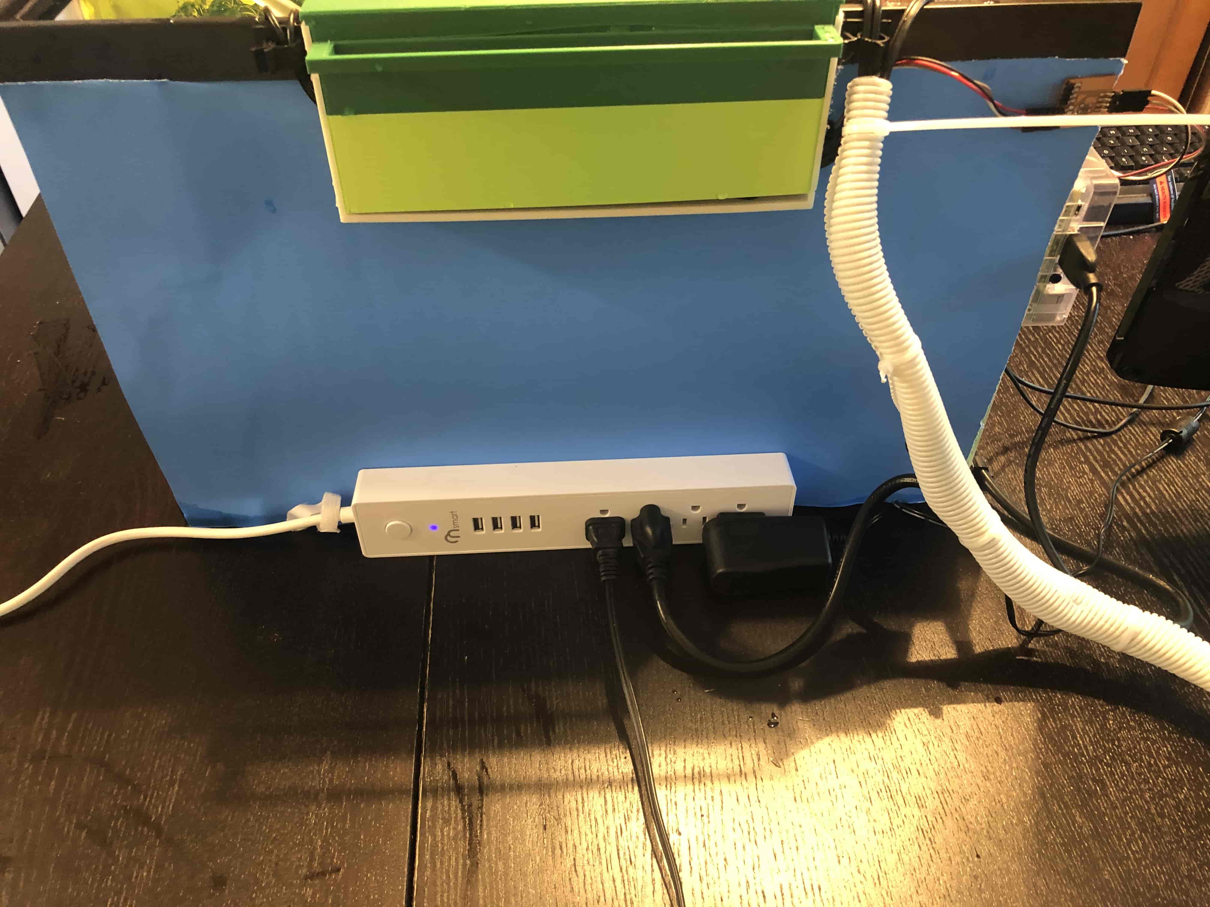
Now on a sadder note I am just going to need to ask you to believe me that we did in fact put the board behind the machine into a box. I do not have any photos of it. I wish I did. If I had it I would show you, and if I could just bring you to the machine I would so that you can see it, but I can't because it's in Kevin's basement and his mom didn't say you could come over. I'm going to link Kevin's page in teh hope that he has a phot if he does then please ignore the tone of this paragraph. Instead just imagine that photo being here.