 Equation for spindal speed
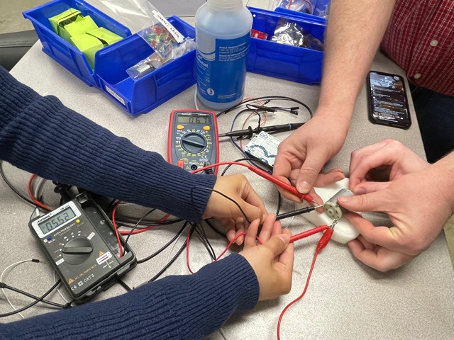
Again for this lab, our Prof. Goodman demoed a variety of different output devices that we could use during our individual assignment. For the lab, we looked into the voltage, current, and power of certain devices when we had them set up. We did this with a DC motor.
Here, you can see us using a setup that involves two different multimeters. One multimeter is measuring the voltage drop across the motor while the other is hooked up into our circuit so that we can see the current.
 Equation for spindal speed
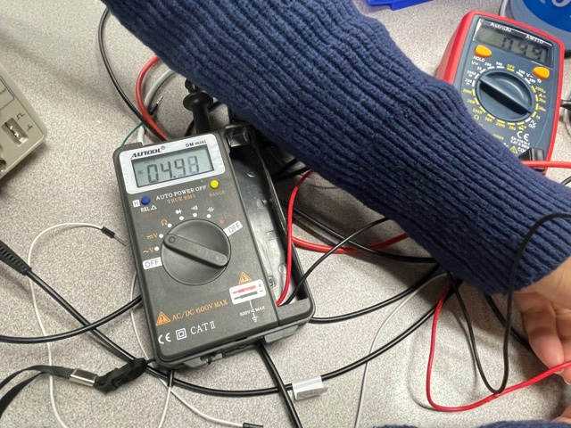
Now when we had someone hold onto the motor we could see that the voltage increased and the amperage went down. This can be seen in the image above. Another thing that we tested was that when someone turned the motor on its own when it was not powered on, we were able to generate a small amount of current.
 Equation for spindal speed
 Equation for spindal speed
 Equation for spindal speed
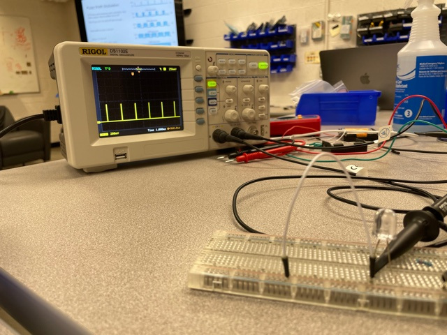
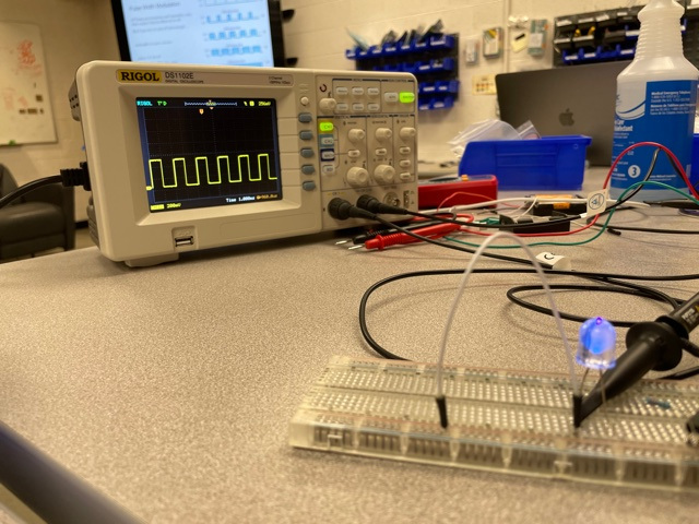
The final thing we did in the lab was to take a look at pulse width modulation. To do this we programmed an LED so that it would fade in and out. It turns out when the LED is fading in and out, the LED switches on and off at a certain frequency so that it can change the amount of voltage that is coming in. Obviously we cannot see this with our eyes, but using the oscilloscope we can see the binary signals.
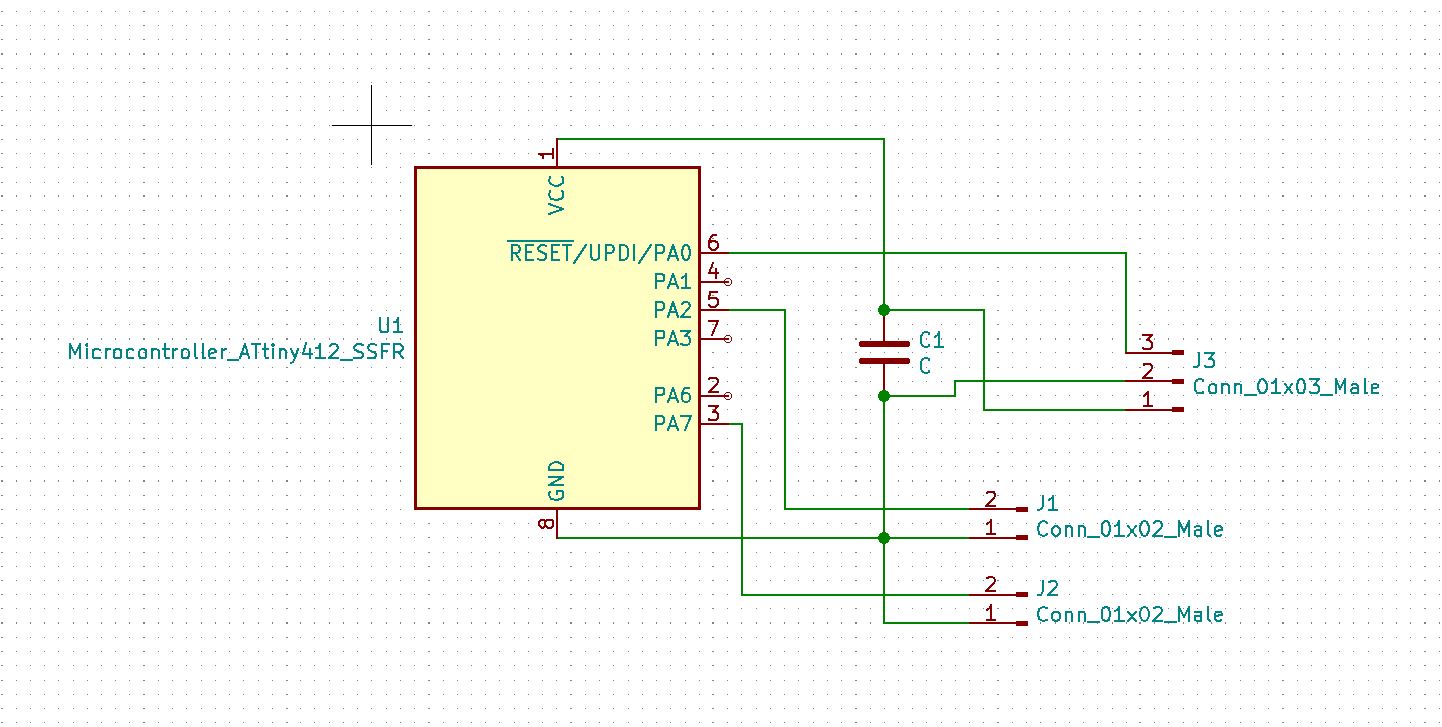
This week I decided that I would do something simple and create a smaller board. I have been mainly working with larger chips like ATtiny 1616, 3216, and 1614 so I decided I wanted to create something with a smaller chip likean ATtiny 402. You can see below that the schematic says that it is an ATtiny 412, but for some reason when I milled everything out, the 412 didn't fit but the 402 did. So that is what I ended up using.
 Equation for spindal speed
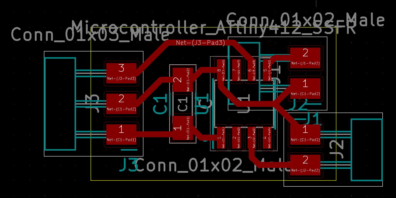
This is how I routed my board. I wanted it to be as small as possible so the board only contains an ATtiny 402, a capacitor between ground and vcc, a 1x3 pin to program, and two 1x2 pins so that I could connect two piezo buzzers if I so pleased.
 Equation for spindal speed
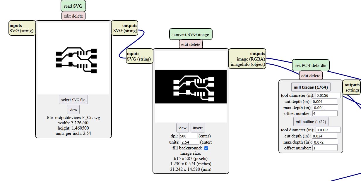
I then used Mods to create the RML files that I would need to run this design out on the Roland. All files and linked down at the bottom of the page for quick downloads.
 Equation for spindal speed
Then I ran the three RML files that I generated (traces, holes, and outline) on the Roland in our lab.
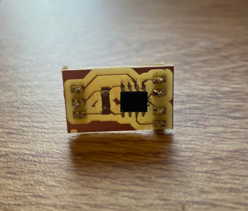
This is how my board came out, This is quite literally the smallest board that I made during this whole class. But I now needed to test to make sure that it worked as I wanted it to.
 Equation for spindal speed
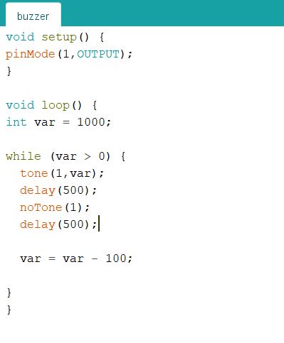
This is some code that I wrote up in arduino. I wanted to use a piezo buzzer for my final project. In my final prject I will be needing to create a countdown for the launch sequence of my model rocket and I would like to have the piezo buzzer there as an added effect. Below you can see me testing the buzzer and the different kind of tones that it can display.
 Equation for spindal speed
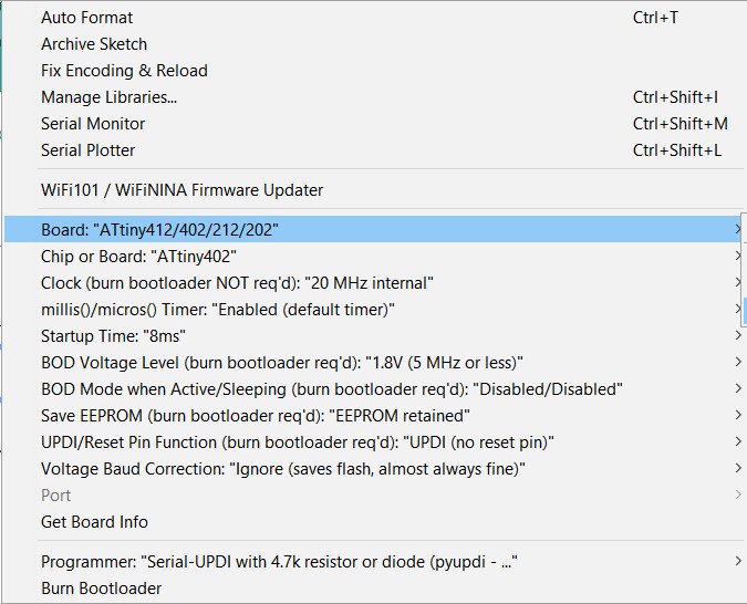
Before running anyhing we need to make sure to set up the ATtiny 402 in the arduino IDE. Below we are going to go to where it says board in the tools drop down menu.
 Equation for spindal speed
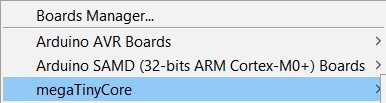
That will open up another dropdown menu where we will select he megaTinyCore library that we installed in a previous week.
 Equation for spindal speed
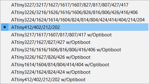
In that drop down menu I selected the option of ATtiny412/402/212/202
 Equation for spindal speed
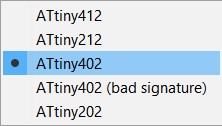
We will now go all the way out and back to the tools drop down menu and where it says "chip or board" we will select ATtiny402 as what we are programming for
 Equation for spindal speed
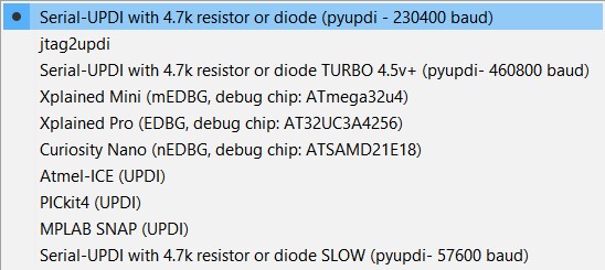
Last but certainly not least in tools again but under programmer we need to make sure that we have it set to pyupdi
 Equation for spindal speed
Below you can see a video of my code succesfully uploading to my milled out board.
Here is video of some example code that I ran on my board before hand so that I could know that everything is working.
And finally here is the code that I am uploading for this week. The code simply just reduces the tone and plays ten different tones then repeats on a cycle.