Another creative week! (ノ◕ヮ◕)ノ*:・゚✧ Learning how to work with 3D printers and 3D scanners. I definitely focused on the printing part almost exclusively, because I found it much more interesting to go from a design on the computer to a physical object. It was also a lot more about properly preparing my design in the slicer software and learning how to work with the printer (than the design itself).
Assignments
Our tasks for this week are:
- Group assignment: test the design rules for your 3D printer(s)
- Individual assignment:
- Design and 3D print an object (small, few cm3, limited by printer time) that could not be made subtractively
- 3D scan an object (and optionally print it)
Hero Shots
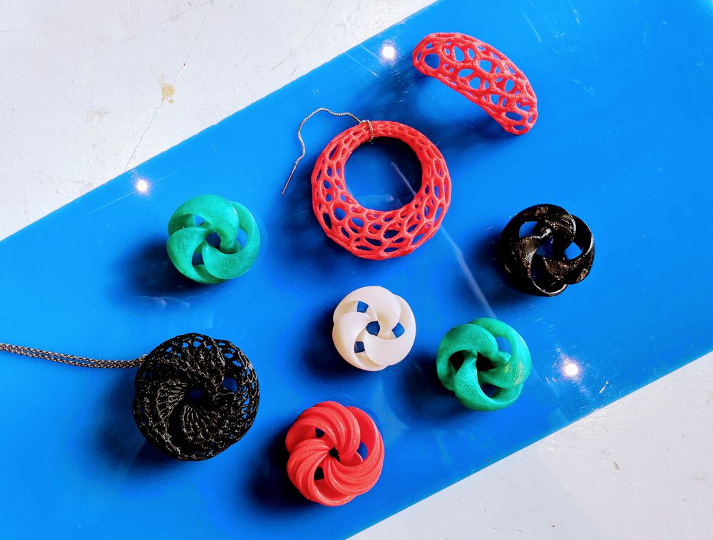
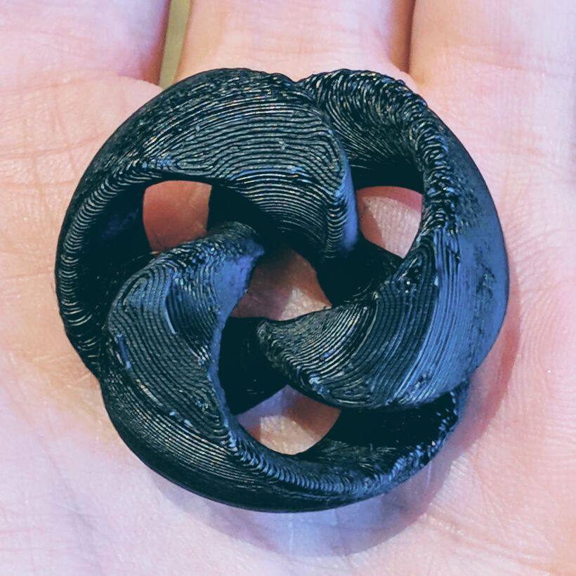
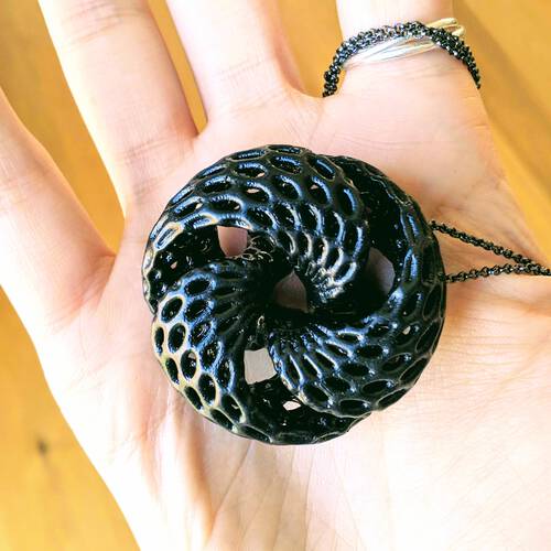
Showing some final results of my small “jewelry & trinkets” collection for the tl;dr and hopefully showing you why the rest of this very long blog could be interesting to read (⌐■_■)
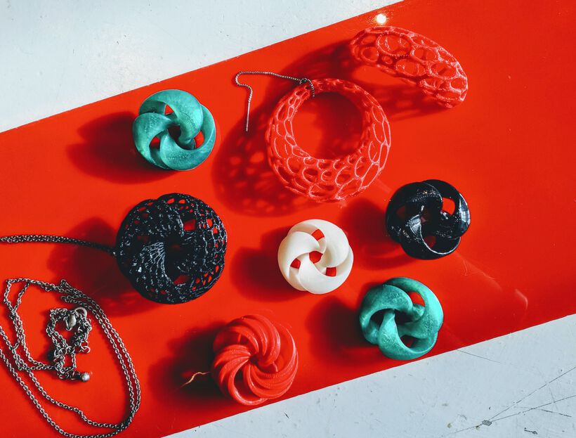


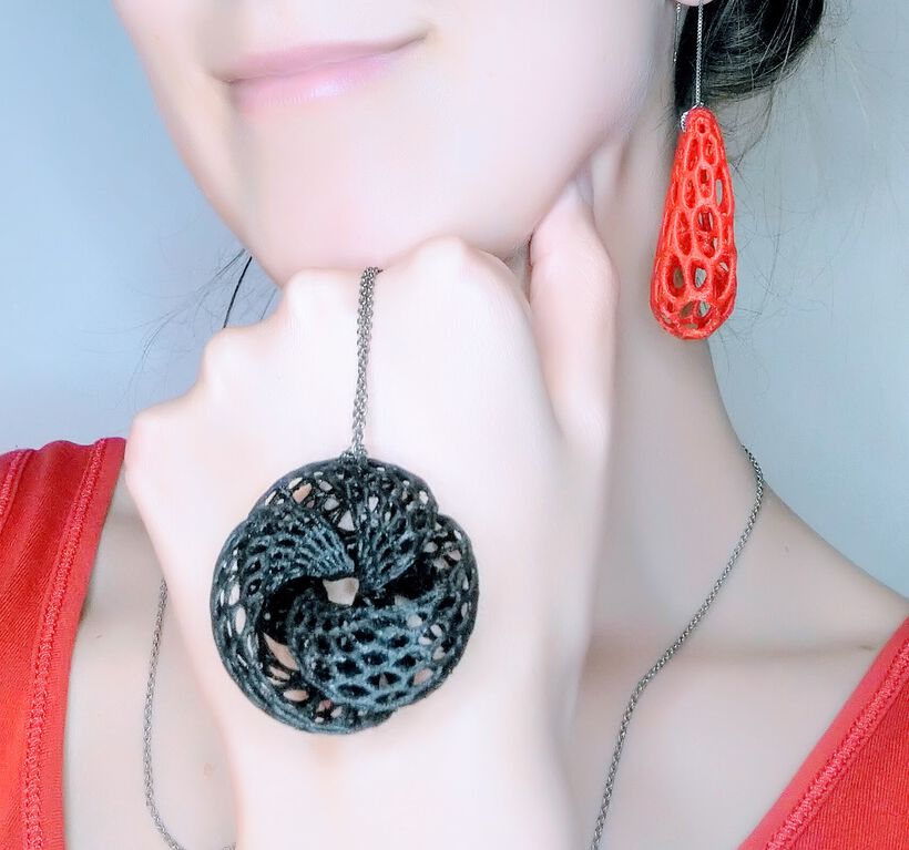
I do quite hate taking selfies, but with jewelry I had better show how it looks right ┐( ̄ヮ ̄)┌
Design
After the giant “ball” I made during the Computer-Controlled Cutting week, our instructor, Henk warned me a few days before this 3D printing week started to not think too big, literally. But only go for something that was small and not higher than ~2-3cm, because the printing just takes so damn long! ( ̄□ ̄)
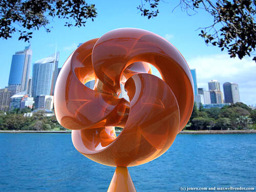
And so I quickly settled on wanting to make something that could be worn as jewelry. A pendant, earrings, a ring, something along those lines. I love working with (simple) geometric forms and beauty created from math, and since a main part of our assignment this week was to make a design that could not be made using subtractive means, I thought something with twists and/or holes would be an interesting direction. This also reminds me of the amazing Quin lamp by Bathsheba Grossman, which was the first 3D printed item that I ever saw to make me want to start 3D printing myself.
Inspiration
My first thought was to see if I could make a 3D spirograph based design. However, after some searching I couldn’t find much about this. Perhaps the third dimension is hard to make look interesting? I did find this crazy inspirational gallery of examples that the author describes as 3D spirographs, but only provides a one-liner of explanation: “Like in the classical setup, we have a point on a disc running along a curve, but in this setup we use a closed space-curve instead of a circle. The curve has a Normal-field, that gives us the orientation for the disc." Which I sadly don’t understand (enough), and I don’t think I have the time to dive into this, since I’m not that sure that the resulting shapes are (easily) 3D-printable. But definitely something I wouldn’t mind going into in the future.
I started looking into other math related art, and found my way to the website of Jotero and damn that was just inspirational beyond words! Even more when I realized that all of their work was done more than 10 years ago! (⊙.⊙) There is (again) virtually no explanation to be found on there, except for some tools that were used. However, most of those have bit-rotted away over the past decade it seems. I did get into a rabbit-hole of looking into Scherk Minimal Surfaces for a bit. Here you can see some examples while this page has some great explanations.
I slowly started to converge to the idea of some sort of twisted circular shape. A torus or Mobius strip for example. And while browsing through a forum in which Jotero posted his work I came across the following shape and knew I would really like to recreate it (but then with a hexagonal mesh across its surface):
The only hint that I had was that Jotero named it a “Triply Twisted Torus”, and thus I started looking into that phrase. I’m not sure if that’s really the “official” name, but I eventually found two videos that were invaluable: The first is an explanation by Professor Carlon Séquin on the math behind the twisted torus shape. And the second was a tutorial on how to create the shape in a tool called Wings 3D, which opened my eyes to the simplicity behind it: a twisted and bend cylinder with the center part missing (⊙.⊙)
Where you specifically twist the cylinder x.5 times while going in a circle, so the end of the left half is connected to the end of the right half, thus forming one structure (and not several disconnected rings).
Possible Tools
When I knew that I wanted to preferably go for more natural, math surface-based shapes, I felt that this wasn’t quite a design that could be created with the CAD tools that I had been using, such as Fusion 360. I therefore asked the internet for recommendations (meaning I posted a question on twitter) and got back a lot of very helpful replies. Below is my summarization of the tools mentioned, in approximate order of how often they were referred:
- Blender
- Using the sverchok add-on | I looked into this for some time, but in the end I felt that I couldn’t find enough examples on how to learn sverchok to try and learn it during 1-2 days. I put it on my wishlist to hopefully learn in the future (this free e-book seemed very interesting).
- Using the tissue add-on | Specifically for the hexagonal mesh structure that I wanted. This mini-tutorial shows a really cool result and this video by its creator explains the concept quite well.
- With the python API of Blender itself.
- Rhino + Grasshopper | Since this is quite an expensive tool, and I didn’t want to start the 90-day trial when I would probably only use it for a few days, I didn’t look further into this (this seems like a useful course though).
- OpenSCAD-like
- OpenJSCAD | Like OpenSCAD but in the browser, and seems to have more options for scripting with JavaScript, such as using loops. Here’s the User Guide and a short intro.
- Python-based
- Three.js | Create the design with Three.js and export to .obj file to open in Blender and prepare for 3D printing. Here is an example of that, with the code.
- Houdini | Perhaps using the free Houdini Apprentice which seems to have a way to export the geometry to a
.objfile. Truly inspirational what can be created with this, but it seemed like too complex of a tool to learn well enough in 1-2 days. - nodi | Seems to be a node-based scripter like grasshopper, but then online. It seems interesting, but I couldn’t really find other examples and tutorials.
From this list I decided to see Blender, something with OpenSCAD, and Three.js as viable options this week.
Creating the Designs
It was that video about creating the triple twisted torus with Wings 3D which was very reminiscent of Blender, plus the fact that Blender’s tissue add-on was exactly what I was looking for to create that hexagonal mesh, that convinced me to go for Blender first.
A Triple Twisted Torus
Still, creating the triple twisted torus with the hexagonal mesh was quite a challenge that took me all day to piece together. Since we’ve moved on from the CAD week to explain the challenges with our tools in detail, I’m not going into all the things I did wrong in Blender to create this design. None of the mistakes were very big and I could always find a solution on the web. Below is the process to create the full shape, and explaining how to do it correctly is already more than long enough I’d say.
- Open a new file and remove the default cube with
x. - Press
SHFT+aand from Mesh select a Cylinder. Set it to have 16 segments (to define the circle). - We need to slice out the center section. To do this we first we need to add four more edges.
- Select the cylinder, hit
tabto go into edit mode, make sure you are in vertex select and select the middle 6 vertices (multi-select withSHFT). - With all 6 selected press
Jto create two new edges between them. - Repeat the same step for the bottom.
- Select the cylinder, hit
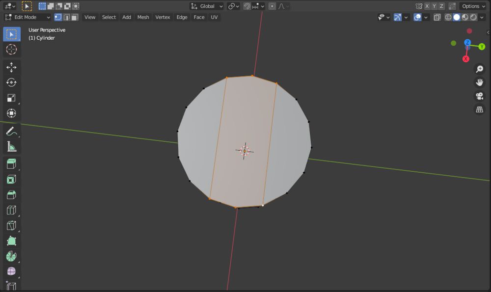
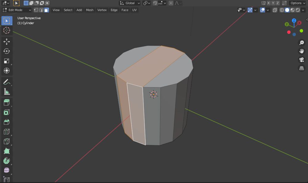
- Switch from vertex select to face select in the top-left of the window and select the faces in the ring around the cylinder.
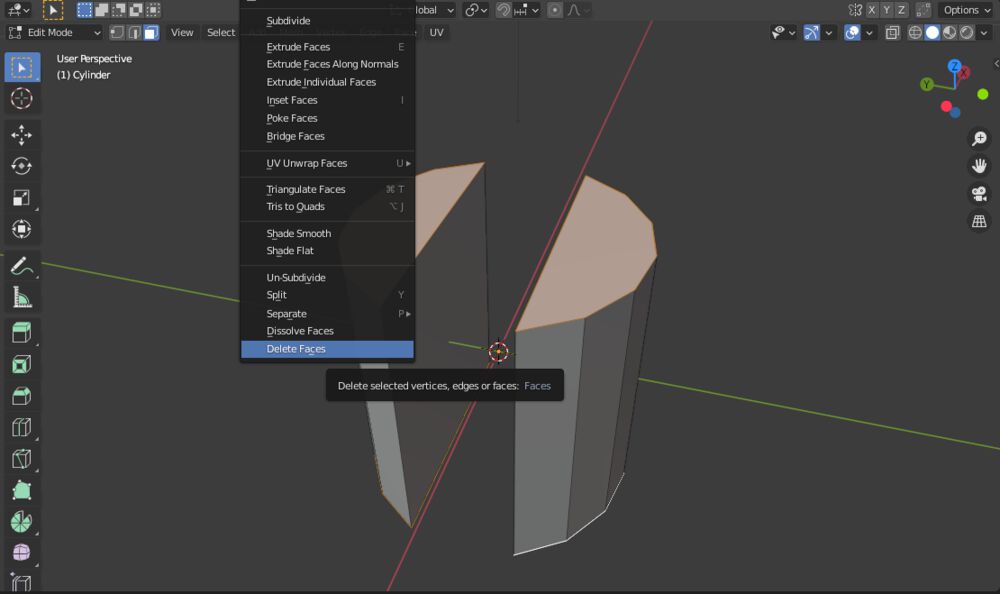
- Right-click on the selected faces, and choose Delete Faces.
- That will create hole in the center, to close the hole:
- Switch to edge select.
- While holding
⌥select one of the edges next to the hole, this will select the entire loop around the hole. - Press
Fto add a face. - Repeat on the other side.

- Because we’re going to spin this cylinder into a circle, we need to remove the top and bottom faces. Like before, go into face select and select the two top and two bottom slices that remain of the circle. Right-click and select Delete Faces. This will leave you with two tube like shapes.
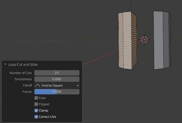
- Next we need to create more facets along the height of the cylinder, using a loop cut.
- Press
CTRL+Rto start a loop cut. Blender will show you the possible loops in the slice if you move your mouse over it. When it shows the horizontal one, click it, and click again without moving your mouse to center it. - In the Loop Cut and Slide window that opens, set the Number of Cuts to 23 (and make sure the Factor is set to 0).
- Repeat on the other side.
- Press
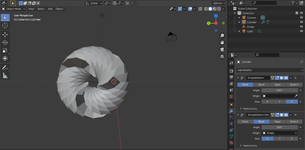
- Now we’re ready to twist and bend the shape using the Simple Deform modifier.
- Along the right Properties panel, go to the Modifier Properties tab (the little blue wrench icon) and add a Simple Deform modifier. Select a Twist, set the angle to 540° and the axis to Z

- Add another Simple Deform modifier. This time choose Bend, with an angle of 360° and the axis to X.
- This will not leave a gap in the middle, which I do want. I don’t know if this is the best way, but we’ll create an empty to use as the origin of the bend.
- Deselect the twisted cylinder, press
SHFT+Aagain and go for Empty -> Plain Axes. - Press
GYand move it 1 unit towards the left. - Select the cylinder again, and in the Modifiers, choose the new Empty as the Origin.
- Deselect the twisted cylinder, press
This shape is the base with which to work. Since the next steps will be destructive, to be safe, create a copy and continue with that.
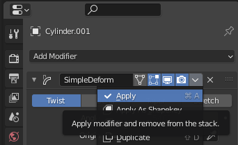
- We need to apply the deform modifiers so the edges we can adjust will follow the twisted torus, not the cylinder:
- Go into object mode and select the (copied) cylinder.
- For the top most modifier, click the little down-arrow next to the camera icon and select Apply.
- Do the same for the other modifier. Now the edges and vertices follow the twisted torus.
- To clean up a little, select the torus and right-click to go for Set Origin -> Geometry to Origin.
- At the seam where the cylinder was placed together, there are now overlapping edges that will cause problems later on. These need to be merged.
- In edit mode with vertex select plus having the Viewport Shading set to Wireframe (along the top-right), and while looking at the torus from the side, drag your mouse across the area of the seam to select all the vertices in that area.
- In the Mesh menu (along the top), go to Clean up and then Merge by Distance.
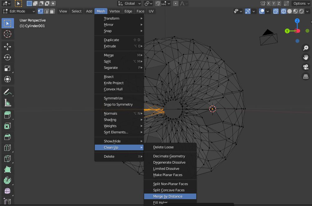
- The default distance of 0.0001 should be fine, and a little note along the bottom should say that a bunch of vertices have been removed
- It will look better in the next step if we add simple bevels to the sharp edges where we cut out that central section.
- Apply a Bevel Modifier to the torus.
- By default this will bevel all the edges. However, I found that in this case, you can use the Limit Method, with angle selected to (at least) 30°, to only bevel the desired edges. Set the Amount to 0.004 units and leave Segments to 1.

- You can also create (destructive) bevels by selecting the edges that you want to bevel and pressing
CTRL+B. Move the mouse to set how large the bevel will be, and the mouse wheel to define how “round” it should be.
The next step is again destructive, so create a copy of the torus and continue with that.
- Now we’re going to apply the hexagonal grid on top. For this we use the Tissue add-on. Make sure it’s installed and loaded.
- Within the viewport press
Nto open up the right tab of options. One of the tabs is Tissue. - With the torus selected and in object mode, select Convert to Dual Mesh. It creates a better looking mesh in my opinion than using the Dual Mesh.
- Within the viewport press
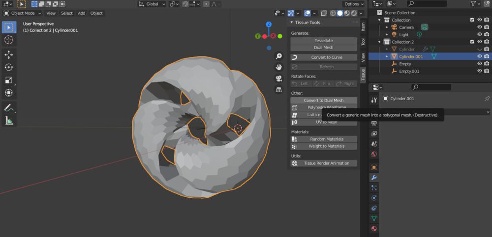
- Next, select Polyhedra Wireframe, and use a Thickness of 0.15 units, press Ok.
- This will create a new Wireframe object, so hide the original torus.
- For a final smoother look, add a Subdivision Surface modifier to the wireframe shape, with a Level of 2.

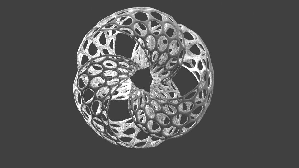
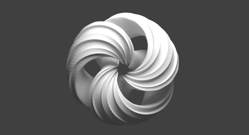
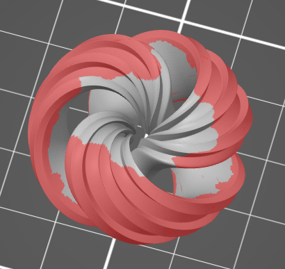
Adding a few lights, using the cycles rendering engine (with some quick and dirty settings), and below you can see the final design:
Now this needs to be saved as an .stl file to import into the slicing software that will convert it from a 3D model to something the 3D printer can understand. Select the model that you want to export, and in File -> Export choose .stl. Along the right of the save panel you have some handy settings.
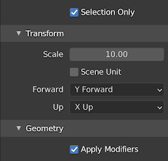
I generally make sure to have Selection Only and Apply Modifiers selected. I also noted that I often need to scale things up a little from the units I’ve set in Blender (I might need to look into that). And you can switch the orientation from Blender to decide what should become Up and Forward.
There’s also this handy blog and video about preparing your Blender files for 3D printing (although I didn’t need this for my designs).
Fixing Your Mesh
One mistake in Blender that I do want to go into was the fact that for a while I couldn’t apply the tissue wireframe function because apparently something was wrong with my mesh. I kept getting the error from the tissue add-on that I had naked edges.
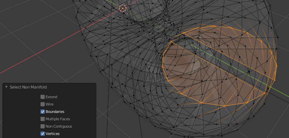
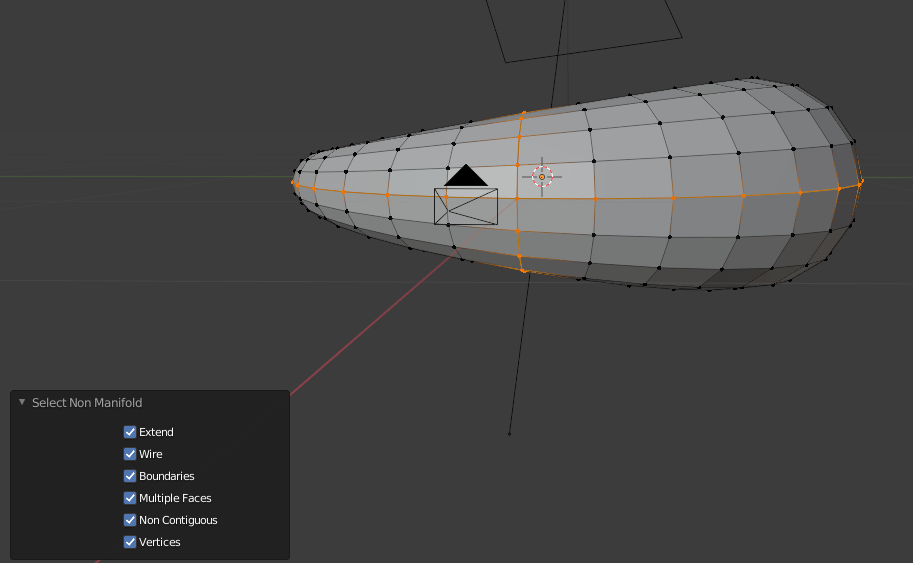
Searching for naked edges I got the impression that this was a term from Rhino and not Blender. However, I did learn that you can highlight everything in your mesh that is somehow “wrong”, called Non Manifold. While in Edit Mode with vertex select make sure nothing is select. Next from the Select menu go to Select All by Trait and then Non Manifold.
This will pop up a Select Non Manifold window in the lower left in which you can (de)activate exactly what type of non manifold trait you want to highlight. I experimented a little with this, and found that if I did this for the first copy of the cylinder, which had become a torus, where I had applied both deform modifiers, that there were some errors at the seam.
Blender doesn’t quite tell you exactly what the issue is, and there’s no magical “fix everything” button. So by googling a bunch I eventually figured out that I had two issues. one being the fact that there were overlapping vertices (which I explained to merge in the steps above). The second issue was that initially I kept the top and bottom faces of the cylinder, while the rest of the torus was hollow inside. These 4 faces were giving the error for tissue to create the wireframe.
I later found out that you can also do these steps more easily with the 3D Print Toolbox from Blender, which is added as a tab to the right of the window and you can see by pressing N.
A Twisted Torus in OpenSCAD
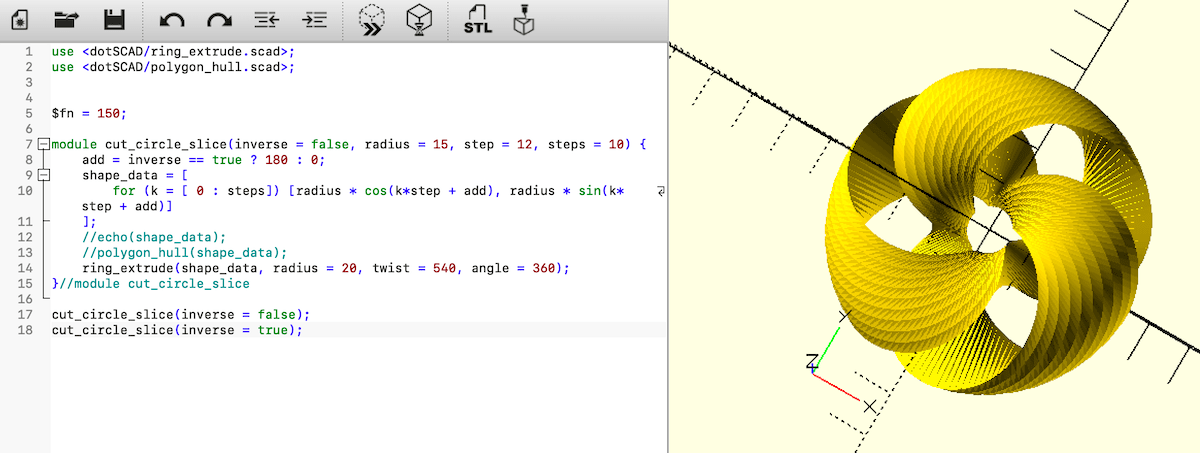
After having truly understood the steps when I recreated the torus with Blender, I understood that creating the twisted torus (not the hexagonal mesh) was actually a rather highly, and straightforward, geometric process. I was therefore curious how far I might get with the CAD tool OpenSCAD.
I would basically need to create a 2D shape of a circle with a rectangle taken out of the center, translated a little away from the origin, and rotated along a circle while being twisted. Well, all of that was possible with OpenSCAD’s functions except doing the twist during the circular extrude, dang it!
Thankfully, in my many searches for inspiration and tools I came across an extremely useful library for OpenSCAD that extends the basic functionality, called dotSCAD. This has a ring_extrude.scad function that also implements a twist option!
However, this function wants an array of locations to use as the shape to extrude, not a 2D primitive. I therefore used some trigonometry to set-up the path:
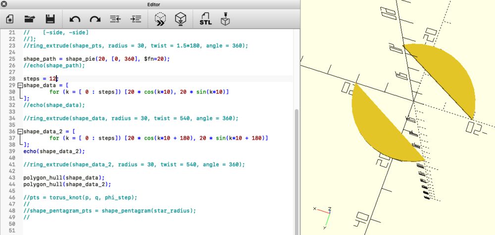
Using the extended ring_extrude function I could created my torus. All in all, what took so many steps in Blender to do, I could remake in OpenSCAD in less than 10 lines of code ┐( ̄ヮ ̄)┌
Of course, when it gets more difficult, such as adding the hexagonal mesh across the surface, I was completely lost as to how to do that with OpenSCAD.
A Torus with Edges
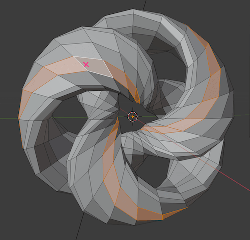
A quick design iteration I made, solely because it made the smooth torus look a little more interesting, was to add extrusions along the outside.
Starting from the smooth torus with the fixed manifold edges in Blender from the previous section, go into edit mode and select face select. While holding ⌥ click on a face, while you mouse is close to the ring/row of faces you also want to select (see the pink cross in the image below-left). With one ring selected, hold SHFT+⌥ to select two (or one) more rings.
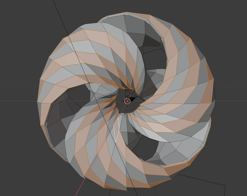
With three loops selected, press I to inset faces. Mouse the mouse until the new faces are just a little away from the outside of the faces. It doesn’t have to be perfect, because after you click you can still make adjustments by opening the Inset Faces window in the lower left.
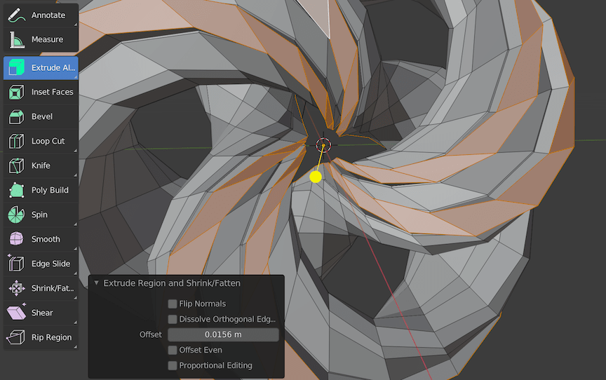
Now we need to extrude these faces, and specifically this needs to be done along the normals to they all move outward. In the edit mode you can long click the Extrude button along the left and select Extrude Along Normals. Click on it, which will create a yellow handle in the origin of the model. By moving that yellow handle you can roughly set the extrusion, after which you can fine tune it with the Extrude window along the bottom left.
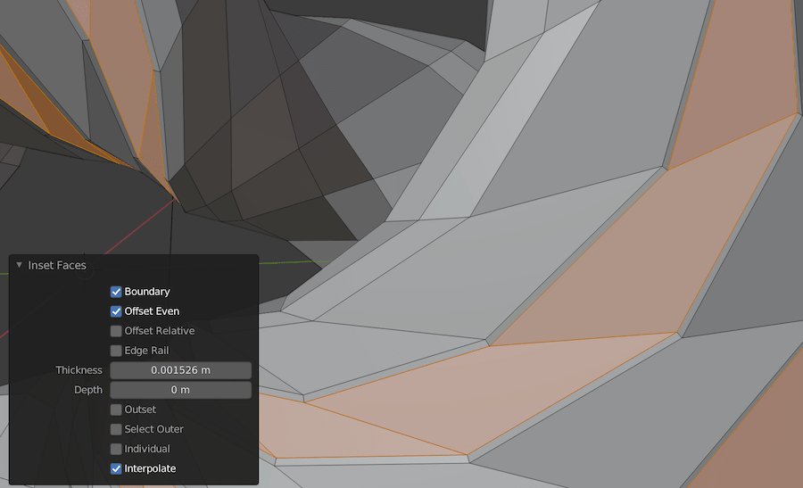
Finally, do another Inset Faces and create a new face just along the outside. These inset faces will make sure that the corners of these edges will look nice and crisp when we apply a Subdivision Surface modifier to it:
A Hexagonal Meshed Earring
To expand upon my little “jewelry collection” I also wanted to make a design for an earring that would fit the triply twisted torus.
I was inspired by this youtube video in terms of what shape to use.
To get this shape, you need to activate the Add Mesh: Extra Objects add-on. Next press SHFT+A and go to Mesh -> Math Function -> XYZ Math Surface.
In the Operator Presets select the Ridged Torus and set the A-H values to what you see in the image below to get the shape I’ve used.

Also be sure to set the U Step to 16 and V step to 8 to get a torus with quite big faces.
You can also create your own math surfaces by playing with the X-Z equations at the top (I played with this only a little).
Be sure to fix the Non Manifold vertices in the same way as we did with the Twisted Torus before.
I also added a few more loops of edges at the top with the Loop cut method I described earlier. And I then shifted those top loops just a little with the Edge Slide function that you can select in edit mode (it’s one of the lower purple colored buttons).

After that I followed the same steps to make the hexagonal mesh as described before to create my final earring design.
I made all the designs within the same blend file, which you can download below:
- The Blender file with all of the designs | blend file
Slicing
To go from the .stl you get from your design program to having it print by a 3D printer, it needs to sliced. It needs to be cut up in the tiny layers that the printer can then lay down. Thankfully, these days several slicer programs exist that can be used with many different models and brands of 3D printer. For example, there is Cura originally made for the Ultimaker. Although I’ve used both, I decided to dive into PrusaSlicer more, which, as the name suggests, was originally created for the Prusa printers.
PrusaSlicer

You add a model by clicking the little cube with a “+” icon along the top. It’s already smart enough to position the object with its lowest point on the 3D printing bed (e.g. I created my torus with the origin in the center, and still it was positioned correctly lying on the bed in PrusaSlicer).
In general you could just quickly change the settings along the top-right:
- The Print settigns (the resolution basically) gives the diameter of the extruded filament. The smaller, the finer the detail, but the longer it will take for the print to finish
- The Filament and Printer which speak for itself
- The type of Support, where you can choose from four options in a list (I’ll go into detail down below)
- The Infill percentage, which is how hollow of filled you want the sections within your model to be that are “inside”
- The Brim will create a flat layer around the model that can make your design stick to the printing bed better. Very useful!
And then press the Slice now button on the bottom-right, which will create a slices model, save the resulting .gcode and have it print. However, you often want to fine-tune the settings more to create a better looking result. Let me elaborate on the steps that I found very useful. But first take a look at how a sliced model looks.
The Slicing Preview
After you’ve pressed the Slice now button and waited a few seconds for the process to complete, you’ll see a sliced version of your model, including any supports and/or brim. You can grab and drag the ruler along the right to see every slice of the model. This can help you assess the process and if you need to make changes to your settings and supports.
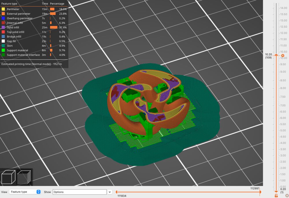
Along the top-left there will be a small window that explains what each color means, and how long the printer will be working on that kind of type (and what % it is of the whole).
With the horizontal slider along the bottom, you can drag through an animation of the exact path the nozzle will take to lay down that layer.
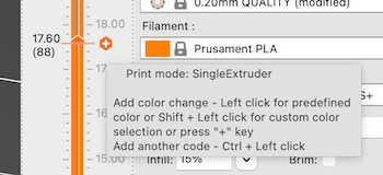
Adding a Color Change
A color change is quite easy to accidentally add if you don’t know about it, as this page describes. Within the slicing preview, when you click the little orange hexagonal “plus” sign next to the handle to drag the slices, you add a color change point.
Let’s now look at the handy ways in which you can prepare your model for slicing in the standard 3D editor view.
Orienting the Model
In case the way the model is imported isn’t the orientation that you want, you can easily move and rotate the object with the icons along the left side. However, I found the Place on face option to be incredibly handy.
While selected you can click on ny of the white transparent “faces” to select as the one to place it on. The program is still smart enough to make sure that the lowest point of your model is at the bottom of the bed, no matter which face you select. The selection only determines the exact orientation.

Supports
Supports are very important for 3D printing. Because the printer works by extruding a thin line of filament, it can’t print in thin air. You need to have placed something below a section that extrudes from your model, a bridge in a way.
Along the right there is a support dropdown with four options. However, through tests I’ve found that those options are generally too crude and are not the most beneficial for the design.

Instead, I found it to be more useful to use the Paint-on support option along the left. For this you need the support drop down to be set to For support enforcers only. If you then use the Paint-on support it will only follow what you paint onto your model.
Select your model and click on the Paint-on supports icon along the left (the little brush). When you click your left-mouse and drag across the model you’ll make it blue in those areas. When you then go into slicing, it will make sure to support those areas (only)
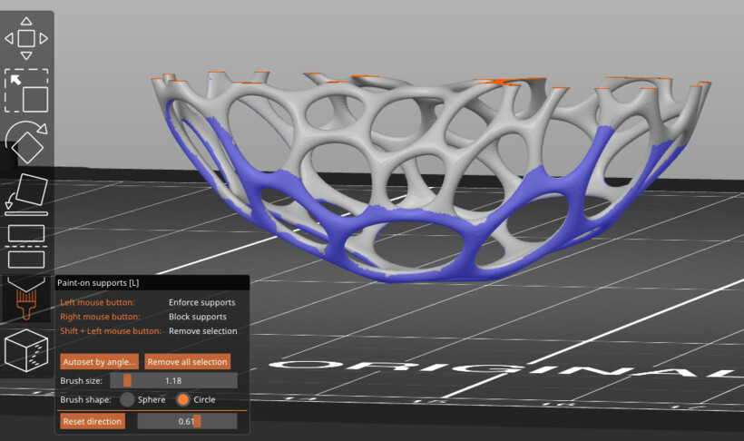

While right-click and dragging will make sure that no supports are placed there. You can remove any painted section by holding SHFT and left-click dragging the unwanted paint.
You can change the size of the brush and make it a circle (only painting on the surface) or a sphere shape (any point the sphere touches that is “outside” becomes painted).
One final thing I found really handy was the use of Clipping of view. This will clip away progressively more of the 3D model from the orientation that you’re then looking at. You can afterwards still move the model around, and the clipping will stay in the same place (see the image above left, where I’ve clipped the top part of the model, and then moved to look at it from the side). With models that have obscured internal sides (like many of mine) this has been invaluable to be able to paint on the inner sections as well.
It can take a bit of time to properly paint your model, go into the slicing view to see the results and make changes to some painting locations again, but you can be very specific in where you’d like supports to be placed.
You can read even more about the Paint-on supports on the Prusa website.
Supports in the Settings
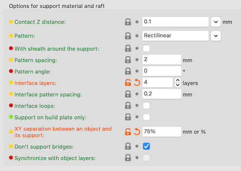
You can also set support settings by going into the Print Settings tab along the top and choosing the Support Material tab along the left. Here you can set more general things such as the pattern, or to enforce support only for the first N layers for example (I didn’t touch any of the other options yet).
You can hover over each option which will show both a short description and is also a link to a webpage with even more info. For the support tab specifically I can highly recommend to read the online explanation.
Seams
Another option I found very useful was to set constraints on where any seams could be drawn. A seam is the place where the nozzle starts on the outer most layer (and ends after having run a full loop around it).
Within the Print Settings tab and then Layers and perimeter you’ll see a Seam position option at the bottom that has four options: Random, Nearest, Aligned, Rear. The default is Nearest which tries to place the seam in the nearest edge of that layer. That generally works well to hide the seam, but for my specific model it actually helped to create a very ugly protruding section, because the nozzle always started and left at that same point at every layer, putting down just a tiny bit more filament in along that corner/line.
I set it to Random instead (you can see examples and an explanation of what each option means on the Prusa website). But I also worked with the Seam painting option within the 3D editor view.
This setting works just like the Paint-on support. However, this time the blue and red colors signify where you want or don’t want the seams to go. In the image below I didn’t want any seams on the outer edges, because I felt one of my tests failed because the seam was always painted in those sharp corners.

In the end I even painted the entire outside red, because I didn’t want the seams there, but was ok with them being along the insides of the twisted torus.
You can check the results in the slicer view. It’s easiest to notice when you drag the bottom slider to see the path animation.
Other Settings
Those were the most useful options to do within the 3D editor view in my opinion. However, there are many more settings that you can change within the Print Settings tab. I think especially the Speed and Layers and perimeters tab can make a big difference on the final result. However, my gathered knowledge of this week wasn’t yet enough to make me want to change those options, especially since one print takes such a long time, so we only had a few attempts on the machine this week.
Cura
Although I played with PrusaSlicer the most, I also quickly worked with Cura, because the Ultimaker was available at one point while the Prusa wasn’t (and I couldn’t find the Ultimaker as an option to set in PrusaSlicer).
Cura works generally in the same way as the PrusaSlicer. You have an overview in which you load your model. You decide which settings to apply, and press Slice to create the slices which can then be viewed and saved as a .gcode for the printer.

However, Cura doesn’t have any of the “paint-on” options of PrusaSlicer. Instead everything is defined with the options panel along the top-right. What is very hidden though is that there are many more options available than are first visible in the list. You need to go to Preferences of Cura, and in there you can activate many more options to further fine-tune the model. For example, I activated the options relating to having more control over the seam position (I didn’t activate much more than that though, expect for having a Tree type as support).
3D Printing
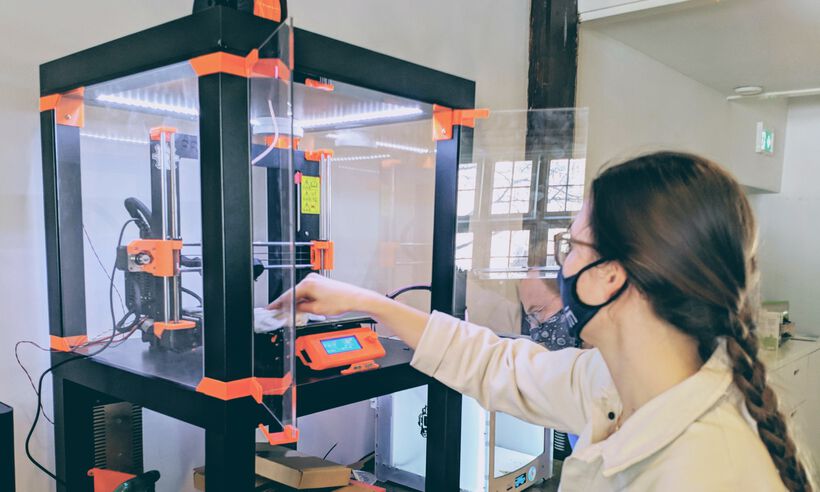
At the Waag Lab there were two (truly) working 3D printers for most of the week (with the Creality Ender added during the end of the week, which I didn’t get to use yet):
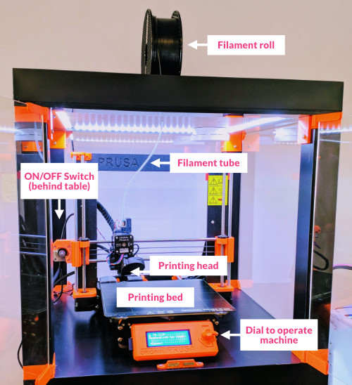
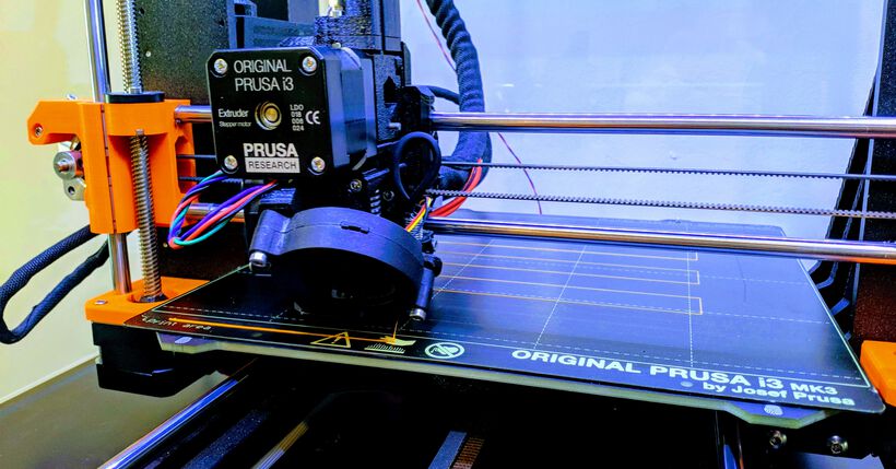
- Prusa i3 MK3S | This machine is open-sourced and (thus) has a large community of people working on creating improvements for it, which you can apply yourself.
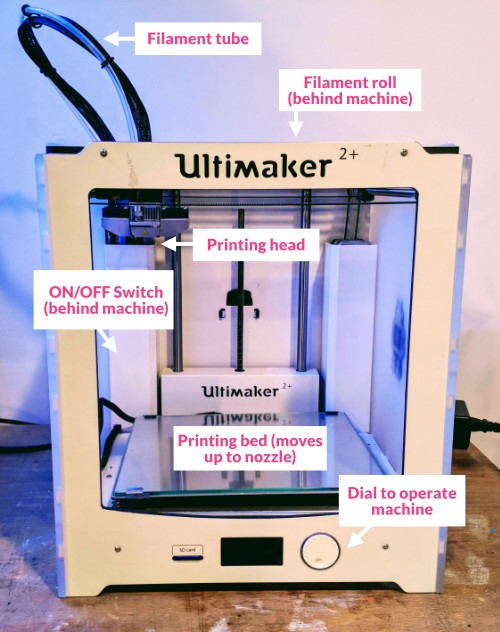
- Ultimaker 2+ | This (rather expensive) machine basically comes put together when you buy it, and works out of the box. However there’s not a lot that can be tweaked to it.
- Creality Ender-3 | This printer arrived at the end of the 3D printing week, just too late to be used sadly. It’s an extremely affordable printer, based on the Prusa and also has a large community. There are many upgrades that you can do to make this printer even better.
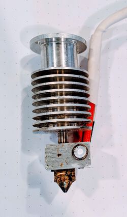
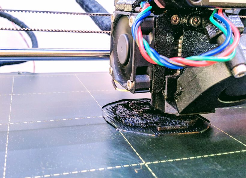
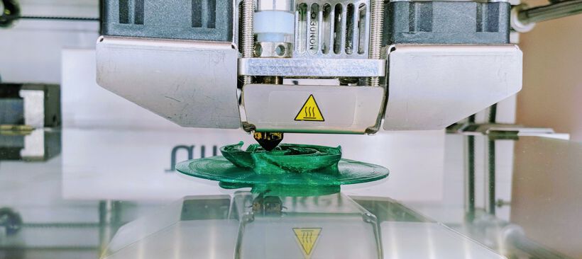
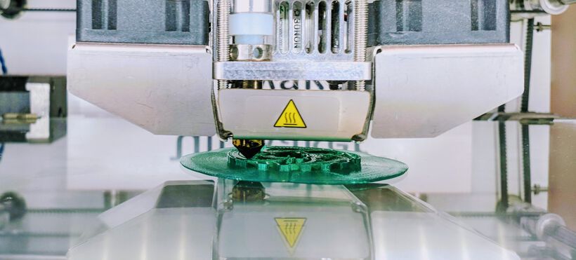
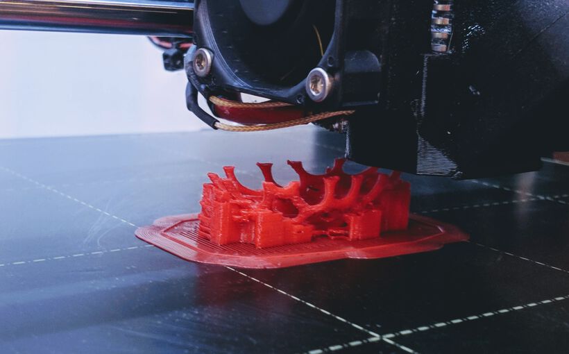
All of these are FDM machines (Fused Deposition Modeling), where a (usually plastic) filament is squeezed through a very hot printing head, which melts the filament and then deposits it in layers on the print bed. These layers fuse together, slowly building up the design, layer by layer. (In the photo below the almost square block just above the nozzle gets really hot, while the metal part above it is made to make sure that part stays cool, which isn’t easy.)
The biggest differences between these machines are:
- The housing: the Ultimaker comes in a stiff frame, a box around it basically, while the other two are very open in their design.
- The placement of the filament motor: the Prusa has the motor that feeds the filament into the printing head right above the head, while the other two have this motor attached to the frame, thus having a much larger distance between the point where the filament is being moved versus where it comes out of the printing head. For stiff material such as PLA this doesn’t make a difference, but for flexible materials, it’s much harder to push the filament a far distance through the tube to the printing head. Flexible materials can therefore go wrong more easily when the motor and printing head are farther away. It’s therefore better to use the Prusa to print with flexible materials. (However, you can get a motor for the Ender to get filament feeding on top of the printing head.)
- The filament thickness: The Prusa and Ender both use filament of 1.75mm thickness while the Ultimaker uses 2.85mm (all three have the standard nozzle size of 0.4mm).
Filament Types
There are several different types of filaments that can be used to 3D print with. More and more are being developed and they are getting more affordable. The main ones at the lab are:
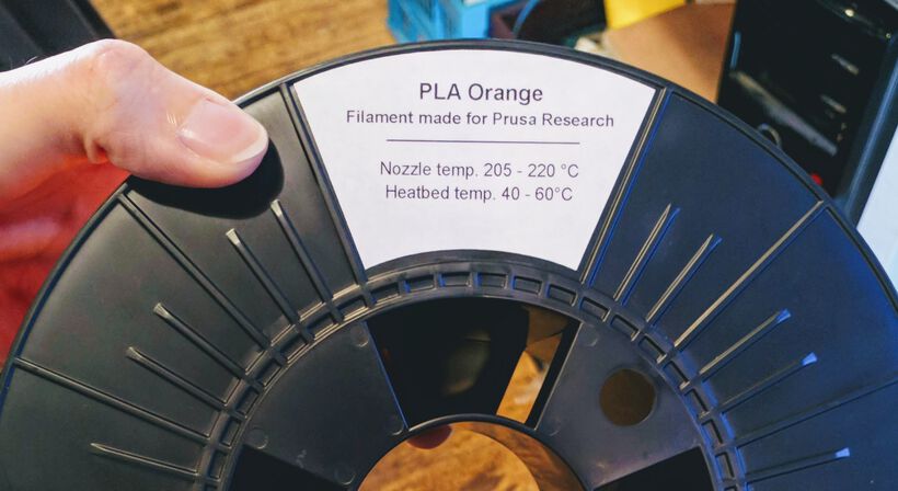
- PLA | Nozzle ±200 - 225 °C - Bed ±40 - 60 °C | Polylactic Acid is the base of 3D printing. As a biodegradable thermoplastic it’s more environmentally friendly than most types of filament. It’s very sturdy, doesn’t have toxic or offputting fumes during the printing. Available in many different colors.
- CPE | Nozzle ±255 - 275 °C - Bed ±70 - 90 °C | Co-polysters are stronger than PLA and are very durable.
- ASA | Nozzle ±250 - 270 °C - Bed ±100 - 120 °C | Acrylonitrile styrene acrylate (the improvement upon ABS filament) are good for outdoor use, but are very finicky to print with, because its sensitive to heat while it’s being printed.
- PVA | Nozzle ±180 - 210 °C - Bed ±35 - 60 °C | Polyvinyl alcohol is ideally used as supports that can be removed, because they are water soluble! However, you need a dual-extrusion FDM printer to work with it.
There are also some exotic materials, such as:
- Wood and Cork based. However these are very bad for the printing head and nozzle, because it sands against the inside
- Carbon based. In case you need some truly tough materials. However, this is also not good for the printing head and it’s generally better to use a really hard nozzle.
- Tribo is a filament that’s extremely durable and therefore a good material to use as components within machines that have moving parts.
- Current-Conducting materials. Very expensive and could have a very high resistance I believe?
Some tips about filament:
- With all filaments, you want to make sure to package them in a zip-lock plastic bag to keep moisture from getting to it.
- Make sure that the filament role is nicely rolled up and doesn’t have any tangles that could clock up the line while you’re printing.
- It’s good to know what material was printed before you start your print. Because a little bit of the previous material will still be stuck within the printing head that needs to come out first. In case the previous material has a higher melting temperature it might become very difficult to remove if you set the printing head to a lower temperature of the new material.
You can find extensive information about all of these filaments from the All3DP website.
Changing Filaments
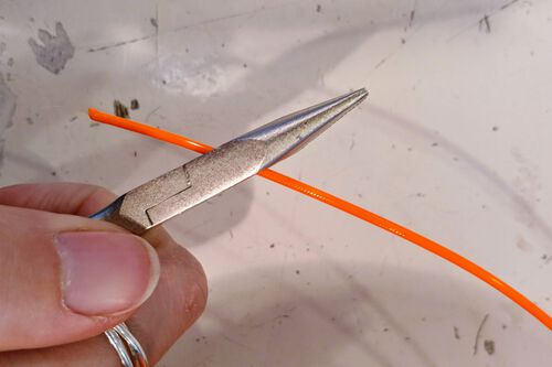
Assuming we’re starting with no filament loaded, you first need to choose what material and color you want to print with. Once you’ve taken the roll of filament from the bag, cut off the end of the wire at an angle of 45° so you can more easily push the wire down the filament tube running to the print head.
Place the filament in the holder of the machine. For the Prusa that is a rolling bed that is placed on top of the machine’s outer enclosing, and the Ultimaker has a filament holder at the back of the outer enclosing.

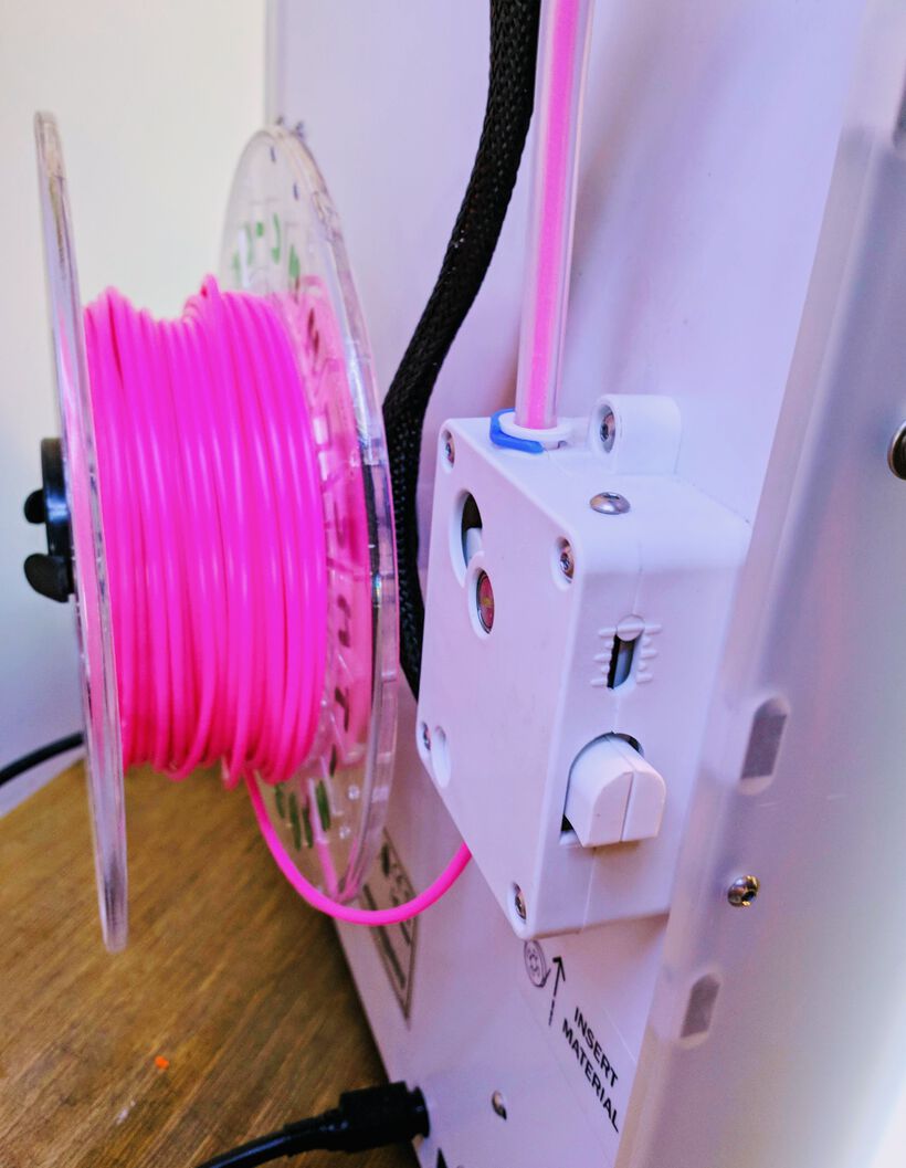
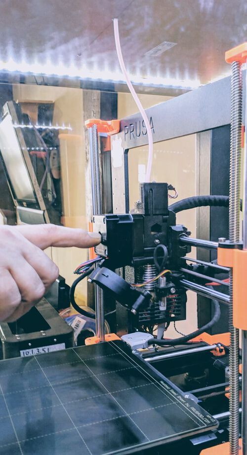
Next, push the (now pointy) end of the filament down the tube all the way to the printer until you can’t push it in farther. For the Prusa, that location should be around the middle of the motor block that sits on top of the head (see the photo below left). The rest is up to the machine to pull down.

Turn the 3D printing machine on. For the Prusa there’s a (well-hidden) switch at the back of the back-left leg. The next steps will follow the directions for the Prusa, but it will be similar for the Ultimaker.
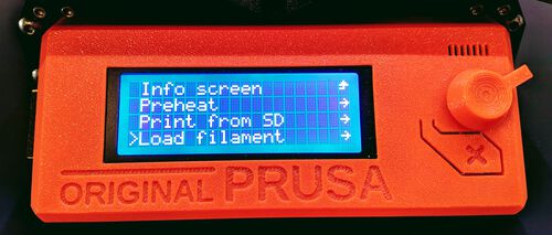
From the main menu select Load filament after which you have to choose which material you’ve loaded since each will have its own nozzle and bed heating settings.

With the material selected the printer will heat up the nozzle and the bed. The temperature of the nozzle can be read from the info window. It takes about a minute to heat up. The info window will then keep the machine at that temperature while it asks you if you’re ready to start for the filament loading with Press the knob to load filament. While you gently hold the filament at the point where it’s pushed down the filament tube, press the knob on the machine. You should feel the filament being pulled into the tube. If not try and press the filament down a little more, until you feel that the motor grabs it and pulls it down.
After a few seconds the info window will ask Filament extruding & with correct color? It’s highly likely that this won’t be the case the first time it asks. Therefore, select No, which will make the machine grab more filament and push it through. Keep replying with No until a thread of melted filament extrudes from the nozzle. And if you’ve just switched materials/colors, keep on going until it’s the correct color.
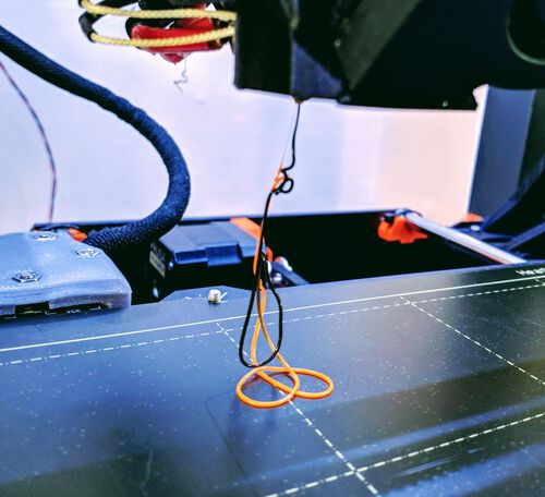
The filament needs to come out in a straight line downward. If it comes out an angle, it means that you have some dirt in the nozzle, which needs to be cleaned.
Changing Filament on the Ultimaker
On the Ultimaker the process of changing filament is quite similar. You also clip the end of the filament at 45 degrees. There is a holder at the back of the machine to hold the filament. You then push the end of the filament into the bottom of the white box (where it says “insert material”). In the menu you follow the steps to load a new material. Once the machine grabs hold of the filament inside the white box, it will push the material into the tube itself all the way to the nozzle. Then you also wait for the nozzle to heat and extrude a slurry of filament until you see the correct color.
First Layer Calibration
There are many ways in which the Prusa printer can and should be calibrated. However, because doing all those takes quite a while (and the printer was already calibrated), Henk only showed us how to do a First Layer Calibration.
You want the filament line to come out a little like a flattened circle on the bed. Too round and it will not stick to the bed, and too flat and your nozzle pushes it down too much, smearing it too far to the sides.

From the main menu, go to Calibration and select First Layer Calibration. It will start off my checking the level of the bed along 9 points (as if the bed was divided into 3x3 blocks) before returning to the bottom-left of the bed and extruding a thick layer of filament (to make sure you have a smooth filament running afterwards). This always happens, for every print.
After that initial step the machine will slowly draw out a pattern across the bed, during which you adjust the z-height of the printer head with the knob on the front.
The calibration will end with a fully filled little rectangle that best shows the result of the calibration. You want this rectangle to look like a smooth evenly spread layer, and when compared to the example images on the Prusa website, it looked perfect.
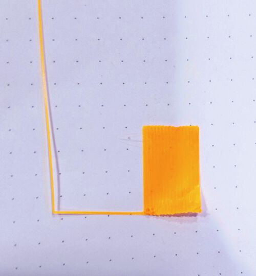
The z-alignment (of -1.055mm) that was applied will then be set at the new baseline.
You can find more information on the many (basic) calibrations that are possible, check out the Prusa Knowledge Base page.
Bed levelling on the Ultimaker
The Ultimaker doesn’t have a fancy (almost) automatic process to get a hood separation between the bed and the nozzle. Instead there are two screws at the front of the plate that you can loosen and tighten yourself. On the Ultimaker Support page you can find instructions on how to level the bed using a “calibration card”, which we didn’t have at the lab (but Henk thought a piece of paper should work). However, after googling some more I found that many people use the time when the printer is laying down the brim to fine-tune their bed.

I tried this as well, and after one failed attempt it worked rather well! It was a little counterintuitive that unscrewing leads to a smaller distance between the bed and nozzle and vice versa. This is because the bed and screws act on a spring system, as the image above shows.
Doing a Print
Normally you do not need to (often) do any calibration and you can immediately go from the steps on loading the filament to starting a print.
One final step to do is to clean the bed to remove any grease (e.g. fingerprints), because you want the filament to stick to the bed. Just using some window cleaner and paper is fine. Henk is not a fan of then using a glue stick on the board to make the bed more adhesive.
At the Waag we use an SD-card to load the files that need to be print. With the SD-card loaded into the slot along the left of the orange panel select Print from SD and next select the name of the .gcode file that you want to print. Now watch the machine doing its standard start-up routine (of checking the whole bed and extruding a thick line along the lower-left side) and then continue to the print.
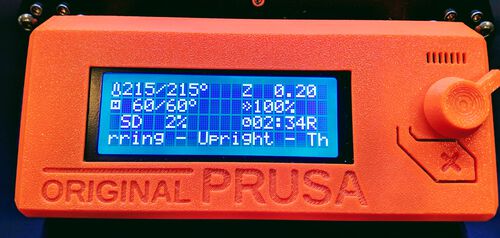
The info window will show you some metadata during the print, of which the most interesting ones to me are the SD% (how far along it is) and the time remaining
At the start it’s important to watch that the printed layers will stay on the bed and aren’t pulled away with the next layers / moving head. In that case you can stop the print at any time with the info window. However, once everything seems to be going fine, you can leave the machine to do its thing, only occasionally checking back to see if everything is still going well.
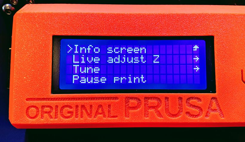
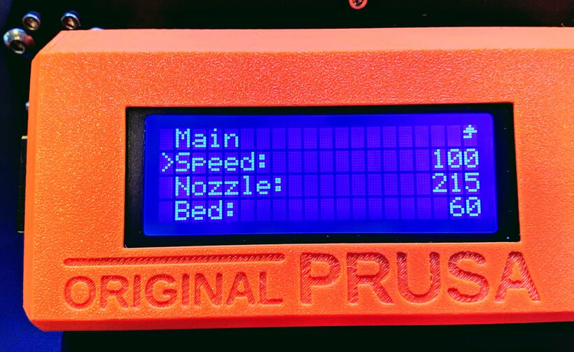
Making Adjustments During a Print
You can make adjustments to the printing settings while the printing happens. Click the knob and you’ll see the options, such as the z-level. Select Tune and you can then adjust the speed (100 means 100% of the speed you set in the slicer software), but also the nozzle and bed temperatures.
Finishing a Print
Once the printing is done the printer head will move to its base (generally the top-left). You can use a spatula like tool to remove the print from the bed. However, our Prusa printer has a magnetic thin layer on top of the printing bed. You can take off this entire layer and then by slowly bending the layer you can loosen the 3D print from the bed.

Finally, the filament needs to be removed. From the main info screen scroll down to Unload Filament. The machine will heat up the nozzle again, and once it’s done it will say Please pull out filament immediately. When you see it, pull the filament from the top of the tube out quickly. Take the roll of filament off of the machine, roll the wire up nicely, and package it in the plastic zip-bag to store it away.
Post-Processing
For a perfectionist like me, the prints coming out of a 3D printer are…. well, not quite the level that I’d prefer, those lines! (◎_◎;)
Since I’m not really the type to print useful items, no utensils, but decorative, small and delicate things, the lines that are visible on a print are quite bothering to me.
I therefore decided to look into some different ways to post-process a 3D print, but I only wanted to investigate methods that weren’t using either highly dangerous materials or was involving a rather dangerous process.
Stringing
One thing that works really well and is very easy is that you can remove stringing where the filament let just a tiny string of filament between jumps by blasting it really short with a heat gun.
PLA Smoothing
PLA is the most used filament, but it’s not the easiest to post-process. What I’ve found is that the general method is sanding. Lots and lots of rounds of sanding, with increasingly fine sand paper, preferably used wet, and possibly using some wood/car filler in between to fill in any left over holes.

I personally don’t mind the time this will take. However, this really only works well if you have: a bigger print that can withstand some force and where you can reach the entire surface (or in other words, this won’t fit any of my designs very easily…), but you also have to paint the model afterwards, since the sanding and filler will discolor the print. This and this video show the process.
I sanded a few of the prints that I made and found that they are very easy to sand, they turn smooth quite easily. However, the color gets muted and they loose some shine. I didn’t want to work with filler and paint them over afterwards, because I choose those filament colors specifically.
I did try using a hot air gun on a red piece that went wrong halfway (at the end of the week) that I’d sanded to see what it would do to the color. It returned it almost to the original color! But it also slightly deformed the structure (the mesh is so thin). But it could be interesting for thicker structures I guess.
A method that doesn’t involve sanding, but still requires a cover up paint is to first paint it with spray paint and then cover it with a layer of polyurethane. It’s described in more detail here. I didn’t really look into this further, because I didn’t want to paint over my designs.
You can also use a heat gun to smoothen out the PLA. However, the results I saw in videos weren’t smooth enough in my opinion. And you have some risk of deforming the material by overheating.
The acetone smoothing described below for ABS/ASA doesn’t work for PLA sadly, because PLA doesn’t interact with acetone in the same way. According to this video, it seems to work somewhat if you heat the acetone, but I found that too dangerous to try. There are other ways to chemically smooth PLA, however this involves rather dangerous chemicals.
Here is an article that goes into several of the processes to smoothen PLA, including some of the ones using dangerous chemicals.
ABS/ASA Smoothing
One of the benefits of working with ABS or ASA is that it can me smoothed using acetone vapor. The acetone melts the outside of the filament which then evens itself out more, and creates a glossy look across the surface.
There are several ways to do this. The warmer the acetone, the faster the process, but also the more dangerous. I therefore researched cold acetone vapor smoothing. In general you want to enclose the 3D print with acetone vapors for a period of time. Don’t dunk it in the acetone, because this can go too fast, but also leave you with gooey drip marks across the object.
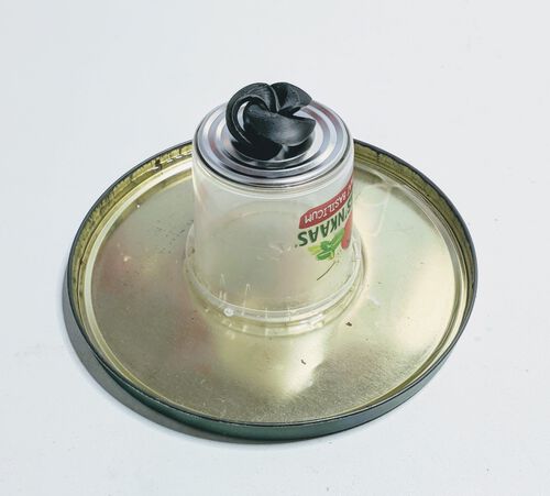
Below are the general steps, but the details can differ a little in terms of the enclosure that you use (a bin with a lid, or a bottom with a dome):
- Do this in a well ventilated area.
- Choose a container that is acetone resistant, such as glass, metal or PP (PolyPropylene) plastic
- I used this article to check what acetone interacts with and that PP was fine.
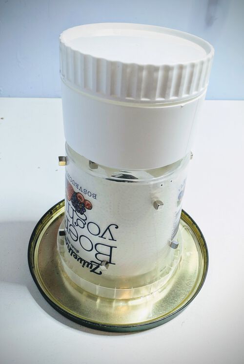
- Enclose this container with paper towels. Make sure that these towels will not touch the object

- Place some sort of plateau on the bottom that is raised (so the object isn’t sitting in a layer of acetone) that is also acetone resistant.
- If you’re using a dome style enclosure, it’s very handy to make the bottom into a water seal by having a larger low “lid” below it all, filled with a small layer of water. Make sure that the paper towels will not touch this water.
- Slightly pour some acetone on the paper towels, not too much!
- Place the 3D printed object onto the platform and enclose it, by either putting a lid on it, or by placing a dome over it. Make sure that air can still escape, because acetone expands as it evaporates.

- You can add a small ventilator to the enclosure to make sure the vapor gets evenly distributed. However, you need to be sure that this ventilator is made of materials that can withstand acetone, and that it’s well insulated. Any kind of spark and your acetone will ignite!
- Check on the object every ±15 minutes to see if you’re satisfied with the process. Having a transparent container can help in this case.
- After generally ±45 minutes the smoothing should be good enough (but depending on the size and how warm the acetone is, it can take less or much more time)
- Take the object out of the acetone vapors, making sure not to touch it. The outside is basically liquid and anything that touches it will leave marks. Let it dry a few hours in a (preferably) dust free location.
I specifically used this article and this video to read up on how to so acetone smoothing.

This article on the Prusa website looks at chemical smoothing for several different types of filament, including PLA and ABS/ASA.
Testing the Printer
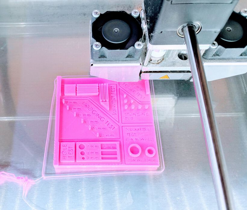
For our group assignment we’re testing what the Prusa and Ultimaker can do. I was in the Friday group, and the group that was in the lab on Thursday had chosen two different tests designs to print. I’ll go into the design that I and fellow student Nicole choose to do on the Prusa and show the result of all four prints (across both groups) in the end.
Nicole and I downloaded the test .stl design from Thingiverse. It tests the printer on 21 different aspects as is mentioned in the description on the site (where it also mentions the best settings). Strangely there are two files in there that are almost the same. We weren’t really sure which they Thursday group used, but we decided to pick the newer of the two, the 3D_test_V3_0.4mm.stl.
We made sure to use the same settings as the Thursday group did on the Ultimaker (which Douwe talks about in his documentation). Within the PrusaSlicer tool we loaded the design and set it to a resolution of 0.15mm QUALITY, with Prusament PLA, supports set to None, and an infill to 30%, sliced it, and save the resulting .gcode to the SD-card of the Prusa.

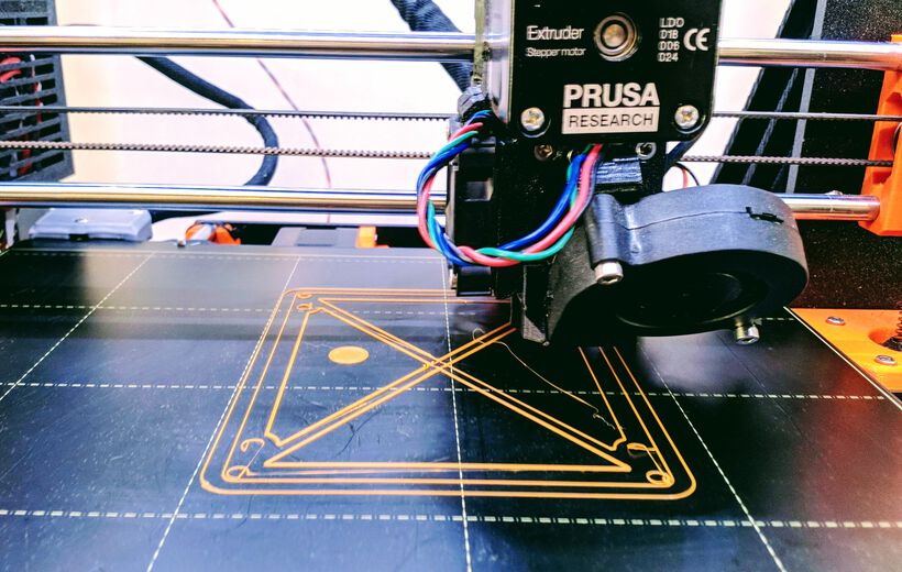
Following the steps as described above we loaded the orange PLA filament into the machine, made it flow and started the print. Fellow student Erwin had performed the same steps for the second print design on the Ultimaker (in pink).

It started out at a speed of 150%, which Henk had set on the rectangle test he made for us (after the base had been laid down, he switched the speed up to 150). Apparently it keeps those tuned settings for the new print. We set this to 120%, and it was ready in only ±1 hour!
After it was (seemingly) done, the Prusa printer told us to Please press the knob to unload filament, which we did, we thought that it was part of the finishing process. However, it then asked us to load a new color. Huh? A new color!? When we looked closer at our design, we saw that it wasn’t quite done. The top of the dome was missing its last few layers. Darn it!
I had already closed my PrusaSlicer file to inspect what I had done wrong sadly. However, after some googling about adding color layers in the PrusaSlicer, I saw how easy it is to add this, and how easy it is to miss as a new user (I described this already in the Preparing a Design for 3D Printing section). I think I must’ve probably accidentally clicked the little plus icon while dragging through the slices that added a new color (>﹏<) Thankfully it only happened at the very top of the design.
Since it was really only the last few layers, we decided that the test object was done enough to compare to the one made by the Ultimaker (⌐■_■)
Comparing the Results
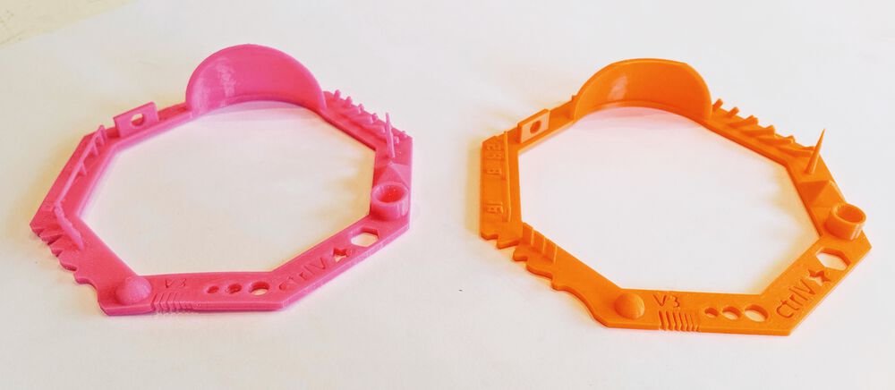
The design on the Ultimaker took about 1.5 hour more to finish and after that it was time to compare all the four test pieces that were printed across the two days (pink is for the Ultimaker, orange the Prusa).

The smaller hexagonal test pieces were almost the same between the two printers. Both for example only printed the thickest three of the walls (next to the edge that has the wiggly cut out). However, if I had to choose, then the Prusa’s result looked just a bit more refined
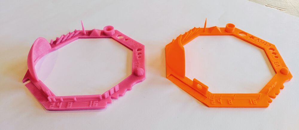
In general the both printers did quite comparable with the square design as well. However, the Ultimaker’s pink version clearly had more droopy lines below the two half arcs.

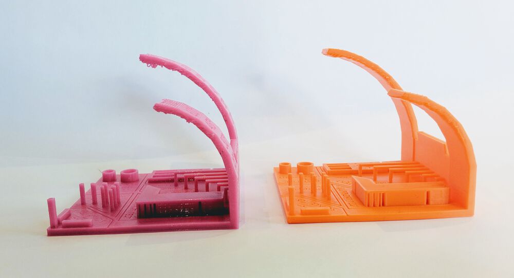
Overall, the Prusa results came out looking just a little better, although both performed more than fine. I was surprised to see that the bridge tests all came out looking really well. Amazed that the printers can span such a large gap!
Printing My Design
With the testing of the printers done at around 15:00, and Nicole and Erwin going home because they have 3D printers to make their assignments on, I was very happy that I could run a test print of my design in the lab to see how it would hold up.
Because the Prusa tests came out looking just a bit better, and I already had experience with the slicer software and printer, I decided to do my test on the Prusa.
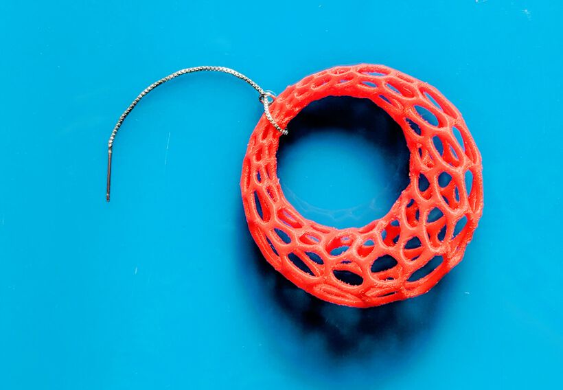
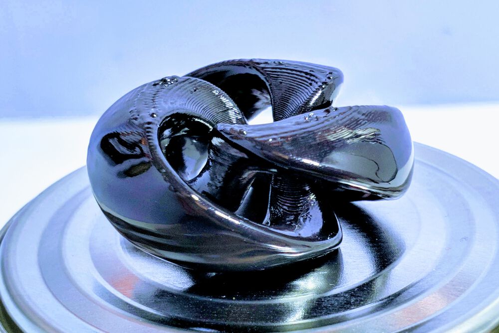
A Jet Black Torus
The night before I’d downloaded and loaded my triple twisted torus model into the PrusaSlicer software. I played around with the basic settings found along the right of the main window, but I had no feeling yet for what was “right”, what settings were good to tweak and where exactly they could be tweaked.
I did realize that setting the support to support on build plate only was not a useful option for my design, due to all of the holes:
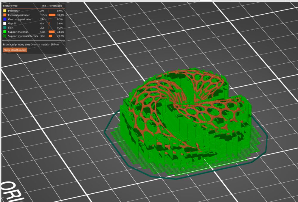
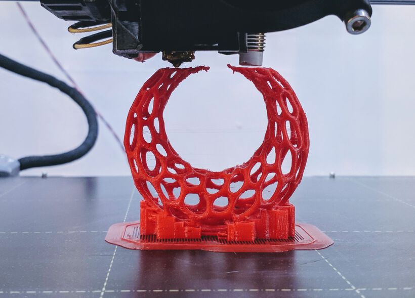
And I figured that using no support would also not work, because the torus is rounded and thus its first layer is very small. Therefore, I showed my design to Henk and our lab assistant Michelle to get some tips.
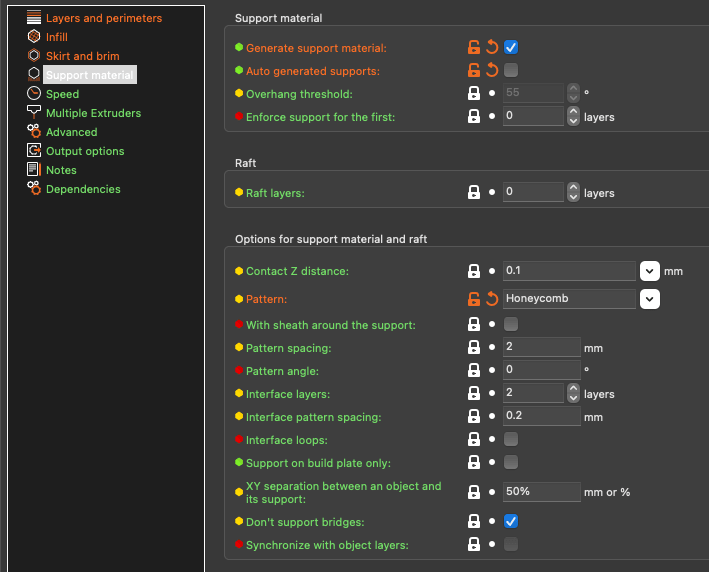
From them I learned that you can do support for only the first X layers. Along the top tabs choose Print Settings and choose Support material from the options along the left. Make sure that generate support material is marked, and then set whatever number you want for the Enforce support for the first:

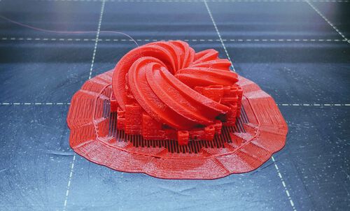
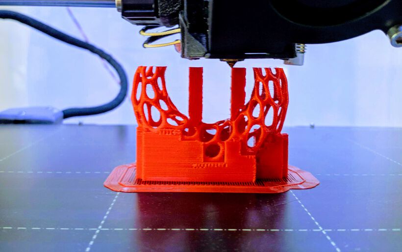
That was really the only special thing I did for my first test. I used a resolution of 0.20mm QUALITY, a support of the first 40 layers, and went for Prusament PLA. With the tiny webbing of my design there was no difference in setting the infill, because there was no place for infill. I didn’t know about the handy Brim option, and thus didn’t turn this on.
I saved the resulting .gcode file to the SD card and selected and loaded the Jet Black PLA from the company that makes the Prusa called Prusament. The filament loading, cleaning of the base plate and set-up all went fine.
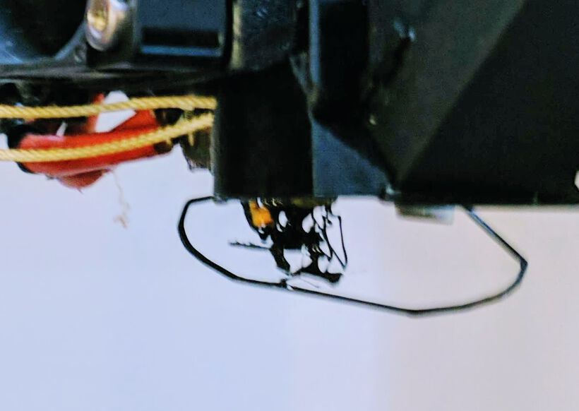
I started the print, but I then noticed that some orange filament was hanging from the thick cable that runs right behind the nozzle. While I noticed it, it got stuck to the black filament and it just made a webbing little mess of everything that came out of the nozzle. Stop Print!
Cleaned the nozzle and tried again. However, this time I noticed that no support layer was being laid down. It seemed that in my clumsiness and general disarray that my laptop folder was in, with all the design files at that time, I’d placed the old quick test slice that I’d made the night before on the SD-card (>﹏<) . Well, might as well see how that went. But I didn’t have to wait long. Only a few layers in and the nozzle pulled up one section from the base plate. Stop Print!

Alright, with the correct file loaded onto the SD-card I started the machine for the third try. And this time it was making it beyond the first few layers just fine ( ^∇^)

I kept checking often to see if it would remain to go well after the level where no extra support would be layered. But that all looked to be going fine as well.
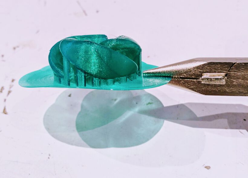
After about 1.5 hours it was fully done. I slowly peeled it off the plate to take a closer look. And although it was done, it was definitely not a beauty ( ̄ー ̄) I hadn’t really expected it to be. I’d heard stories of how difficult it was to make something look good with 3D (FMD) printing.
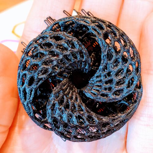
I tried to pull away the support, but because it was so mixed up with the holes in my design it was almost impossible to remove. After about half an hour of peeling with screwdrivers and tweezers below the magnifying lamps (used for soldering) I had most away from the outsides. Another 30 minutes later and I had taken a little more away from the inside, but also broken two legs of the hexagonal mesh. At that point I felt that was as good as I was going to get it.
There was some stringing going on with fine hairs running in between some of the holes. However, a few seconds exposure to a heat gun and they were gone.
On some of the more horizontally running lines it had a few droopy sections here and there. Nevertheless, for a first ever (completed) 3D printed piece, I wasn’t really that unsatisfied. All in all, I did feel that there was much I could improve upon, both in terms of design and in setting up the slices.
I would actually like to recreate this torus with the ASA filament and use some acetone vapor smoothing to it, to see the result, and if the (very open) structure will hold up.
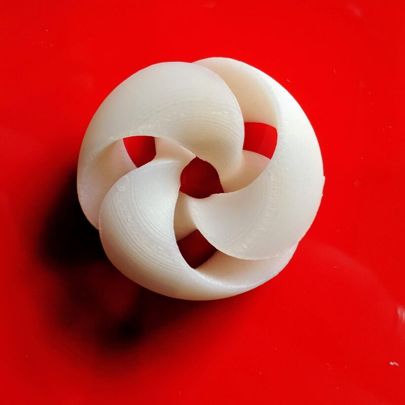
A Tiny White Torus
Since the lines on the 3D printed result were so visible I wanted to do another test at a better resolution. There wasn’t that much time before the end of the day so the print couldn’t take too long. I therefore had to scale down the torus design. However, that would make the wireframe’s webbing too thin. I therefore exported a version from Blender that was 70% of the scale of the original, without the wireframe, but just the smoothed out torus.
Within PrusaSlicer I set the resolution to 0.10 mm Detail and the number of support layers to 20. That should take a little over 1 hour to print. I also choose a different color, Vanilla White PLA.
I started the print, but after about 10 minutes Michelle noticed that one section of the design was no longer sticking to the bed and was being pulled up as the nozzle moved across the layers. Stop Print!
In the photo below, when the print moved to the sharp points, the back of one section would flip upward, away from the bed.
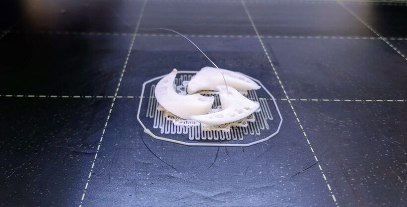
And that’s when I learned about adding a Brim in the PrusaSlicer from Michelle. This puts down a few more layers of filament around the outside of the 1st layer of the design, making for a bigger sticking surface to the plate.
With this adjustment I started up the 3D printer again and this time the brim was enough to not pull it away from the bed. Michelle and I did notice that something wasn’t quite right at those sharp edges still though, they seemed to point upward a little.
Nevertheless, the print finished seemingly fine and from above it looked like a success!

The support came off really easily this time thankfully, with it being a solid shape. However, when I turned the torus around to look at the bottom…
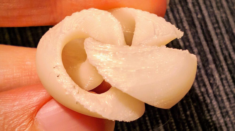
Damn, that looked so rough! Not pretty at all (╥﹏╥) I discussed it with Michelle and she recommended to add a bigger bevel to the edges where the inside and outside of the torus meet. Perhaps if the nozzle didn’t have to make such a sharp turn it would not leave that tuft that slowly started sticking up during the printing, which resulted in the roughness?
Since there’s really only one (not overly complicated or involving rather dangerous chemicals / processes) way of smoothing out PLA, I set about sanding that underside of the white torus. One benefit of the white color was that I didn’t get any visible discoloration from the sanding (how colors can turn more white-ish after sanding). I did get a few black dots of the sanding paper lodged into the material that just won’t come out anymore. However, the sanding was really effective and rather easy and now the white torus feels very nice all over, and looks much better from the bottom side.

Nevertheless, instead of coming up with a completely different design over the weekend to print on my next lab day, I instead wanted to see if I could make (minor) adjustments to the current torus design and play more with the slicer tool and 3D printer settings to see if I could make it work. And thus my next tests began…
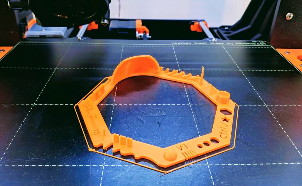
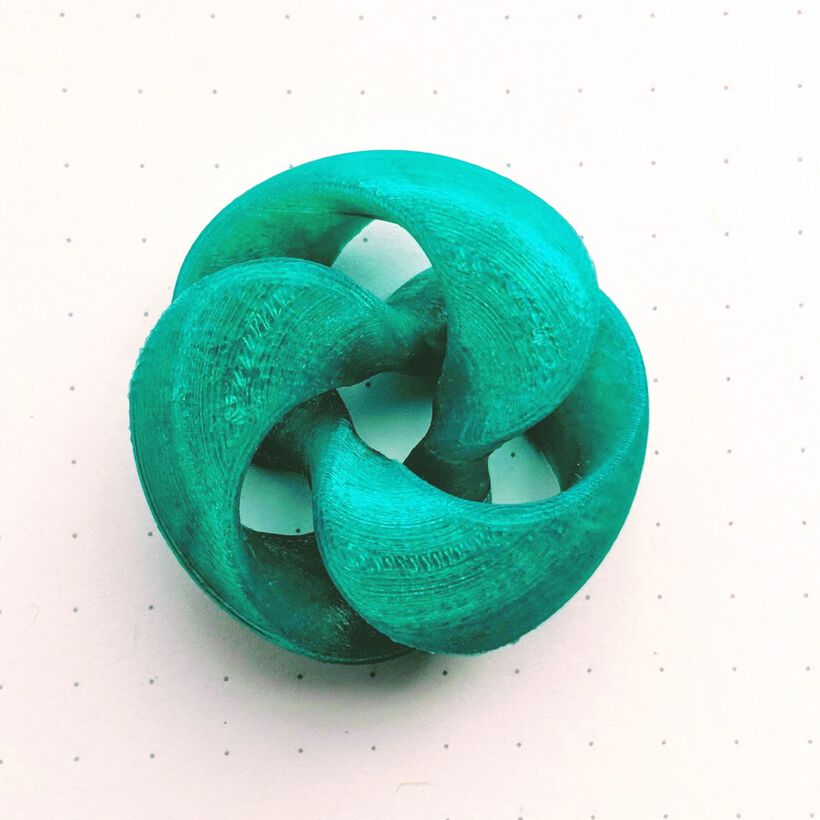
A Jade Green Torus
Back in the lab on Monday the Ultimaker was available to use. I loaded a lovely jade green filament and choose to print the “torus with edges” design. In Cura I only added a brim to the model, set the seams to random and nothing else, to see the result of having no support.
However it looked horrible right from the start and after only a few layers it started to pull up the print from the bed, so Stop Print!
The layers, which were only the “edges” of the torus still, were just one goopy mess!
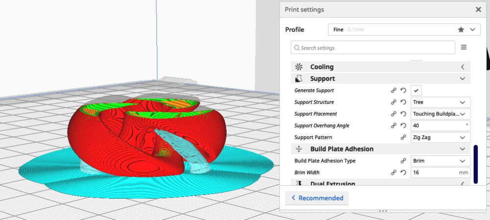
Therefore, I decided the torus with the edges wasn’t a good fit for now and loaded the normal (filled) torus into Cura, but I also set the brim width from the default 8mm to 16mm to add some more “sticking power” to the bed.
Sadly this next print didn’t go well after the first layer either. It was as if the nozzle was just too close to the design and started to bump into it when it did the outer perimeter. Or somehow the perimeter was bending upward? After a few more layers it even managed to pull up part of the giant brim from the bed. Stop Print!
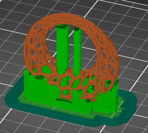
I felt that perhaps the distance between the nozzle and the bed was too close. I looked up how to do a levelling, and read that many people use the period during which the brim is being laid down as the moment to fine-tune the bed. I made a small change to my model within Cura, turning on the support but choosing the Tree method (the light blue structures in the image below).
I started a new print, fiddling with the front two knobs to try and create a better distance between the nozzle and bed. At first I made big changes, just to see what would happen. The image below (where the printer went from the outside inward) shows the result where I first made the bed and nozzle too close, resulting in the line spread out lines along the outside, after which I made the distance quit big which eventually resulted in the lines being pulled up and separated from the rest along the inside. After that point I stopped my test.

I restarted my print for the 4th time on the Ultimaker, this time doing a proper bed levelling while the brim was being laid down. And although the first layers were being laid down a little better than before, it still wasn’t looking very good sadly.
I showed Henk and he suggested to lower the bed temperature and lower the speed. I thus lower the bed temperature from 60 °C to 55 °C and set the speed to 80% (while the printer was still running), and almost immediately the print was improving.
The lower levels looked quite rough from the bad start, but the rest of the print seemed to go much better.
Eventually the result reminded me a lot of the white torus I’d made the Friday before; From the top the torus looked really nice, but turn it around and it was very rough around the edges and the very bottom sadly ಥ﹏ಥ So the bigger bevels hadn’t really made a difference sadly.
The tree-like support that I’d set-up in Cura had had basically no impact on the result from the printer, but at least it was quite easy to remove.
Since the bottom looked much too rough, I decided to take my chances and started sanding away. It was really easy to make the torus smooth to the touch. However, as I expected, the sanding was making the PLA turn whitish and it lost its shine. I went from a roughness of ±200 to ±2000 in progressive steps, sanding it wet, but I never got completely rid of the white sheen.
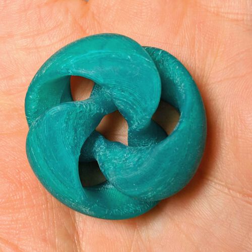
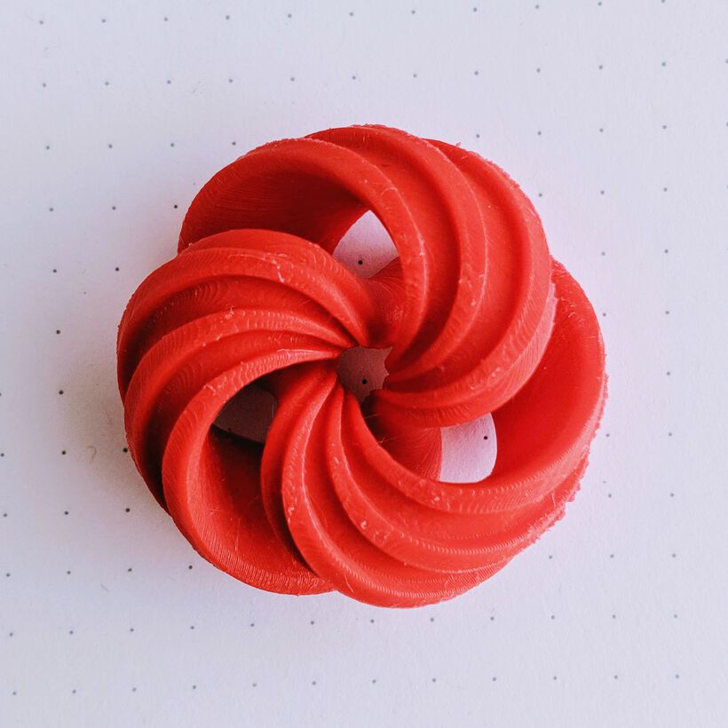
Nevertheless, it looked great from the top, and thus I decided to turn this version into a brooch, then nobody will see the back side anyway (⌐■_■)
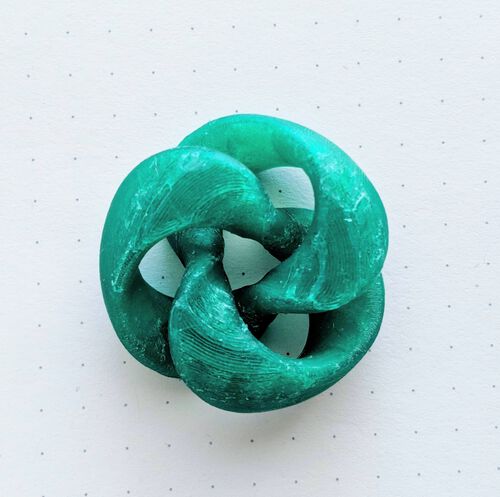
A Second Jade Green Torus
Even though I had increased the bevels, it had apparently not been enough. I also wasn’t sure if perhaps the first few millimeters of the design needed some support, because it looked so rough in both the white and jade torus. I therefore adjusted the bevels to be even larger and choose the Normal support type in Cura, while placed a zigzag line all around the bottom side and along the edges that were so rough in my actual print.

The first layers were being put down really perfectly, no tufts being pulled upward at all.
Above right you can see the result with the support clearly visible. The edges looked really nice (and the top as well), so I was very hopeful that it had finally worked for the full design. I started to pull out the support, and for the higher sections it was quite easy. However, the support around the bottom of the torus had completely melted together with the torus (ᗒᗣᗕ)՞ And while pulling it away (using a lot of force) it left clear marks along the bottom of the torus (right image):
It was an improvement over the previous jade torus, but I wasn’t the success I was hoping for sadly.
A Red Edged Torus
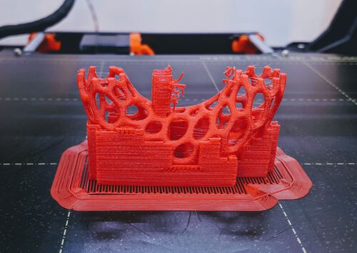
Because I felt that the Prusa was performing better in laying down the first layers, I wanted to give the edged torus design one more try. My other torus tests so far seemed to indicate that the bottom section and the edge towards the top could use some support. I therefore draw some paint-on support in the PrusaSlicer in several very specific locations. I also made the outside completely red with the seam painting to make sure that no seems would be placed there.

The run took 2h21m to complete and although I didn’t spot any strange things happening during the run, I was afraid that the support would be melted with the torus again…
Thankfully it came loose easily enough (it still took some force though). However, even with all of these supports the bottom was extremely rough and sagged 눈_눈
And at this point I had to admit defeat and that I couldn’t make this torus design work with my current knowledge of 3D printing. The overhang along the build up of the first ±20% of the bottom, and the overhang along three of the bottom edges was just too great to create a smooth looking design from below.
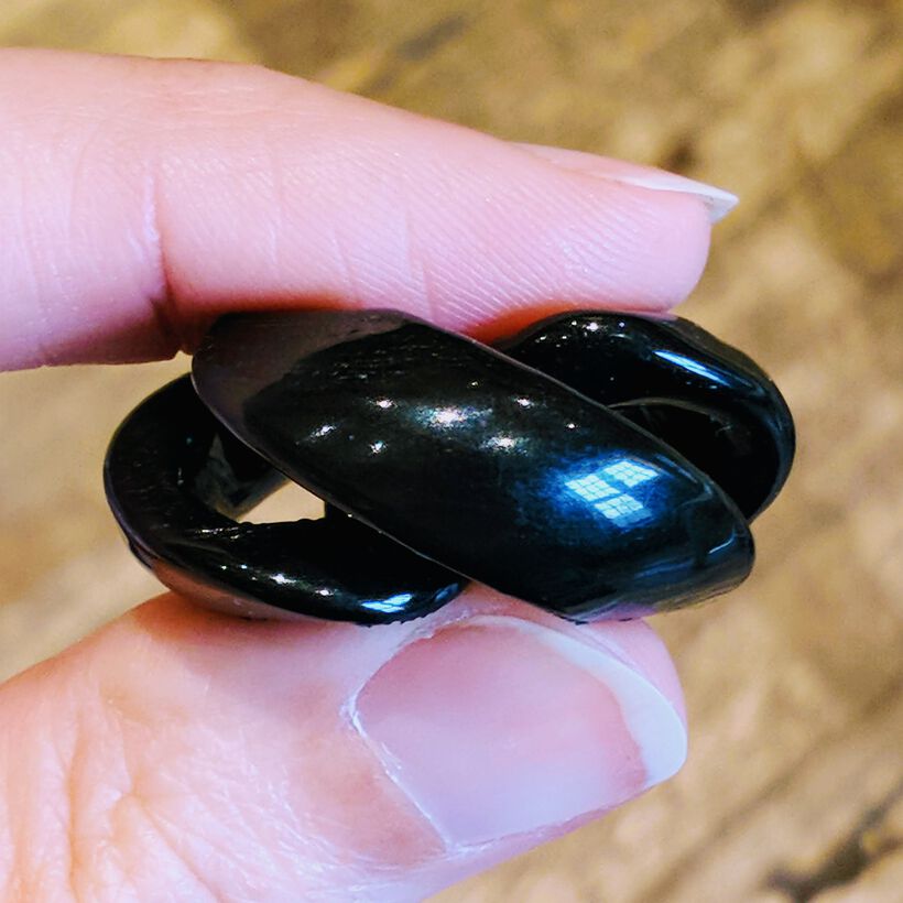
A Jet Black Torus from ASA
Because the lines that you always see on a 3D print (when made with FDM) I really wanted to try and make one torus with ABS or ASA filament and then perform an acetone vapor smoothing step at the end.
I choose the Jet Black ASA filament, used the torus design with the biggest bevels I’d created and in PrusaSlicer set a wide brim of 10mm, but without any support. From my earlier tests I’d concluded that they made very little difference on the final look (it was rough either way). I used a resolution of 0.15mm instead of the 0.10mm I’d been using mostly before because I wanted to actually have some courser lines to see the effect of the acetone smoothing afterwards.
I was sure to keep the doors on the Prusa enclosure closed, because I read that you need to keep the print with this type of filament in a warm environment. The first two times I had to cut the printing off during the brim stage because the nozzle would have some goo left on the end which became entangled with the brim.

After a third try in which I cleaned the nozzle every time some goo came out while it was preparing and heating up, it finally laid down a good brim and the print could continue.
I have to admit that the printing process didn’t look to go that well. As with my first white torus, the sharp tip along one end of each arm of the torus was still pointing upward and the nozzle was bumping into it on each go around, even slightly lifting up the back end. I guess the big bevel and random seam position hadn’t made a difference after all ಥ_ಥ I figured to just let it continue until it completely failed. But to my astonishment, it finished the whole run without issues, and the back of the torus didn’t look all that crappy compared to the previous ones (^▽^)

I sanded down the back of the torus a little, because the brim wasn’t coming off that well, and I was curious to find out what the effect of the acetone smoothing would be on a sanded section.
Back home I set-up my little cold acetone vapor smoothing station (as described in the “ABS/ASA Smoothing” section of the “Post-Processing” section).
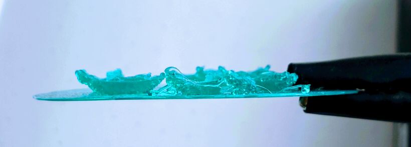
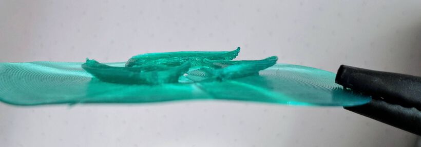
I left the torus inside the dome for ±45 minutes. I had continuously checked through a small opening at the top of my “dome” that I hadn’t put any paper towel on (with a flashlight). I could see that the top and inner part of the torus sadly wasn’t fully smoothed out, but that the sides had completely gone smooth. Because I felt that I was seeing some slight sagging of the outside, I decided to stop the process, even without the top fully smooth.
The sides looked so smooth! I let it dry for the evening. In the morning the sides still looked as if they were liquid, so smooth, but it was completely dry.
I wonder if perhaps I should’ve used a tiny fan inside the dome after all to better distribute the vapors to smoothed out that top and inner part more though. Because although the sides now look perfect, my perfectionist self is still not satisfied with the very clear lines that remain on the top.
The sanded bottom section looked quite nice. The material melted over much of the roughness and sanding residue that remained and the bottom and top are looking very comparable: almost there but not quite.
About a week later I redid the acetone vapor test, and this time hung a tiny fan inside the enclose (we scaled the container up this time, using a larger glass container to make room).

I kept it in there for about 45 minutes, and it did smoothen out the lines on the top and bottom. However, you could see that the part that was facing up during this second run (which accidentally was the bottom) had sagged inwards just a little sadly.
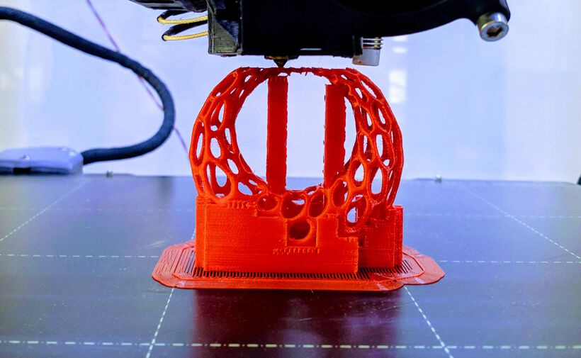
A Red Meshed Earring
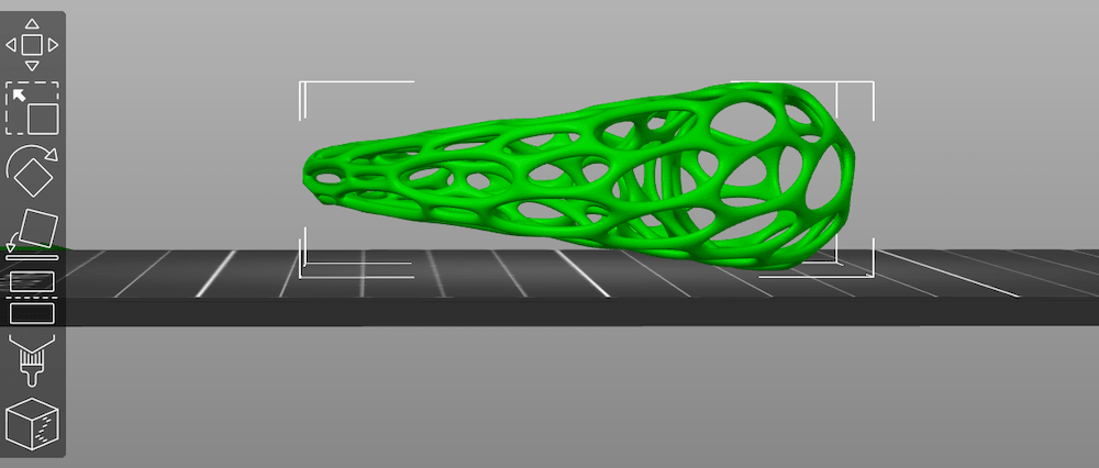
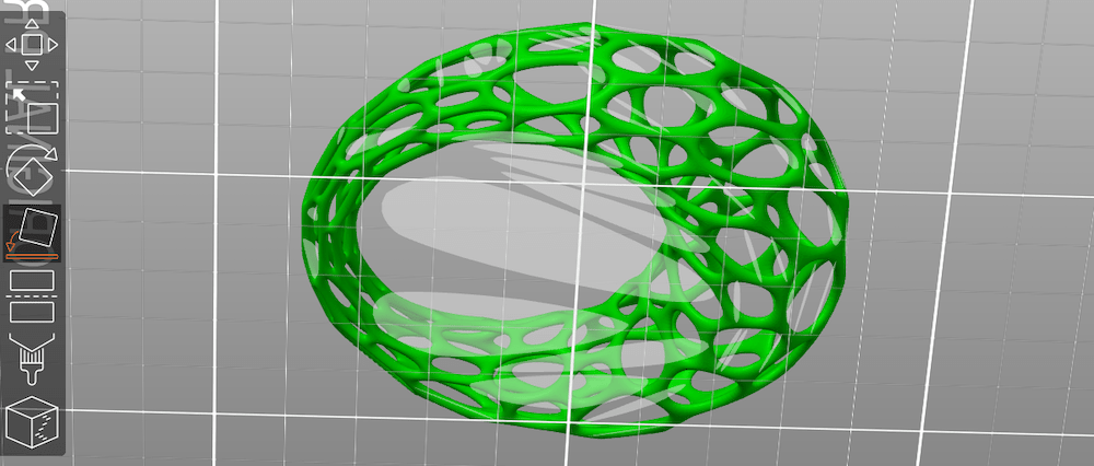
Although I was mostly playing with getting my torus to be properly printed, I also did not want to give up on the idea of expanding my little “jewelry collection” with a set of earrings. Thus, during the weekend I also created a looped earring design with a mesh structure.
Having learned a lot more about PrusaSlicer during the weekend I applied some very precise paint on support to make sure that the outsides of the mesh where supported, but that no support material would be present within the mesh structure.

As you can see, I also placed this design upright, instead of laying it flat on the bed. That’s because I’d noticed in my black mesh torus that there were some flubby parts of the filament on the elongated circle running along the outside (I’ve been utterly unable to capture it on camera with the small design and the blackness of the mesh…). I therefore flipped the earring design upright, so most of the ellipses were pointing upward.
This was a bit of a long run, with about 2h40m to go, but I’d gotten to the lab really early so hopefully a lot of that could be done by the time the other students would start to arrive.
It started really well and the mesh structure grew upwards from the layers with the support. And then when almost two and a half hours had passed and the inner circle was slowly being closed it almost failed completely. The overhang angle combined with how much each new layer was moved inward from the layer below it was too much. Only through sheer luck I think that the two halves of the circle managed to becoming connected after a few more layers ✖‿✖
After it was done I was very happy to find out that the support structure came off very easily. There were still quite some droopy sections along the bottom where some of the openings were more horizontal ellipses than vertical ones. And of course the section at the top of the inner circle where the two halves barely connected again wasn’t that smooth. There were also still some “hairs” running between the gaps, but I “blasted” them off with a quick shot from the hot air gun.

Using a tiny stanley knife I cut of the droopy bits and cut through the hairs. I think the final result doesn’t look too bad from a distance that you would normally see if someone os wearing it as an earring (^ᗨ^)
I took a set of my earrings and took off the metal thread and looped it around my 3D printed one and voila, earring number one complete!
The Other Earring
Earrings come in pairs generally, so I really wanted to make another one. I did want to try and improve upon the previous go. I looked at all the places that the first earrings was a little drooping and added support in those areas very specifically. It was a little bit of fiddling to make sure that no supports were drawn within the structure.
However, I did have to add some kind of bridge that ran all the way to the top, to prevent a second almost catastrophe where the two ends weren’t coming back together again. I placed those two bridges very specifically to make sure that it ran from bottom to top through the opening of one hole as much as possible, so I could remove the support afterwards.
I also adjusted some of the support settings, to hopefully make a support that would still work, but could be removed quite easily, based on the settings that bobstro posted here.
I went to the lab on Wednesday morning to print my second earring. I did put in an ABS red filament for a first layer (I had adjusted the slicer to use ABS filament, because I could test the acetone smoothing on such a delicate structure. However, the red color that I saw appearing from the machine was very faint, muted red, not nice at all. I therefore stopped the print after that first layer and loaded Lipstick Red PLA again.
It started out really well, but after about 2 hours I noticed that the 2nd tower wasn’t being printed! The machine was pooping out a little string at that tower, but it was not being placed anywhere and got stuck on different locations around the design. Stop Print!
I checked out my PrusaSlicer design and saw that the second tower was smaller than the one that had been built. It had apparently been too small to have been built above the point where it was supposed to appear from the bottom of the earring. I therefore made the second bridge a little bigger (by playing with the paint-on support), saved the new .gcode and restarted the print.

I couldn’t quite draw the towers at the point where I felt they needed most support when coming together at the top though, because there was a mesh at exactly those points sadly.
Nevertheless, the print ended with a completed earring thankfully. The support took some force to get off, but not specifically because it was too attached to the mesh, but because how much support was there in the bottom in the first place (and attached to each other). But at no point was I afraid that I’d break the mesh itself. The design has a large mesh hole in the bottom through which I could pull the two internal sections of the support towers out of of the bottom mesh.
With the extra supports that I placed around the base, there were almost no droopy lines along the horizontally oriented ellipses anymore (ノ◕ヮ◕)ノ*:・゚✧ And after a quick blast from the hot air gun I can now wear my earrings as a set!
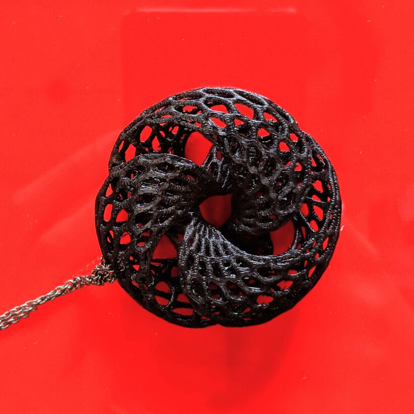
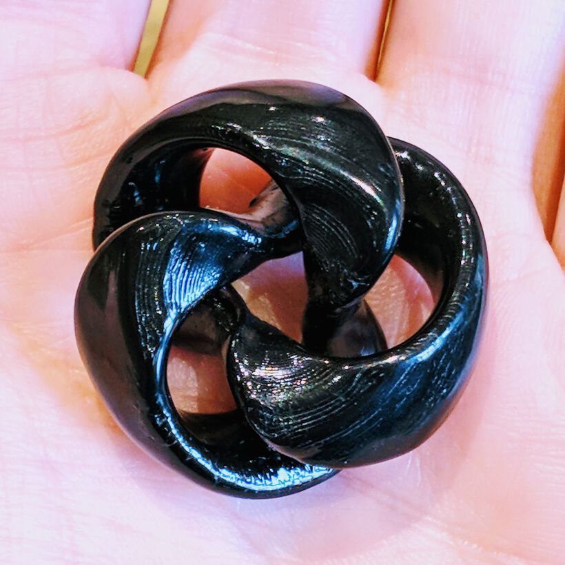
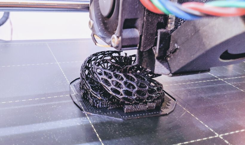
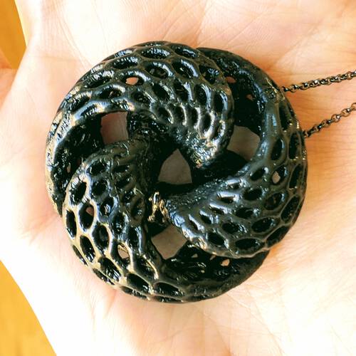
A Meshed Black Torus from ASA
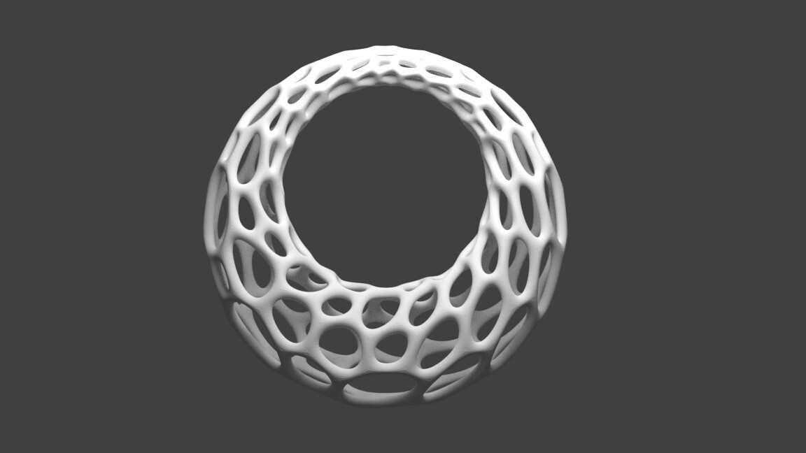
Because the acetone vapor smoothing had such a big impact on the look and smoothness of the tiny black torus, I wanted to do one more test where I created another black torus with mesh holes from ASA and use acetone vapor smoothing on it as well.
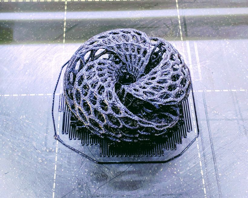
I made the mesh just a little thicker in Blender than the previous edition. Hopefully that would give a little more support. I used a resolution of 0.10mm and the total print time jumped up to 4h26m! The underside of the torus turned out quite rough again sadly, perhaps making the mesh thicker hadn’t been a good decision.
I therefore had to sand the underside of the torus quite a lot to smoothen it out. I saw that the sanding wasn’t really affecting the black color, so I also sanded the upper side of the torus a little to smoothen out the lines a bit already in preparation for the acetone smoothing.
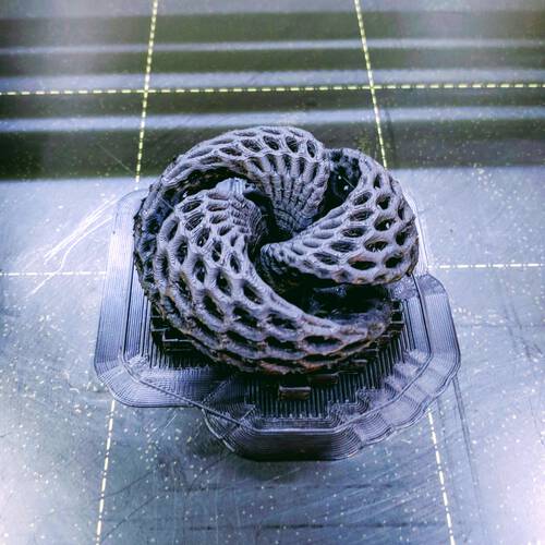
I placed the torus in the acetone vapor smoothing set-up (with the tiny fan), and checked on it every 15 minutes. But nothing really seemed to happen. You could see that it looked a little like it was getting moist in a way, but not the uber-smoothing that I’d seen with the tiny black torus.
After about 2 hours in the acetone (and wettening the paper with acetone halfway again), I figured that it wasn’t going to get any better, so I took the container off to let the torus stiffen again.
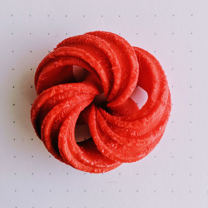
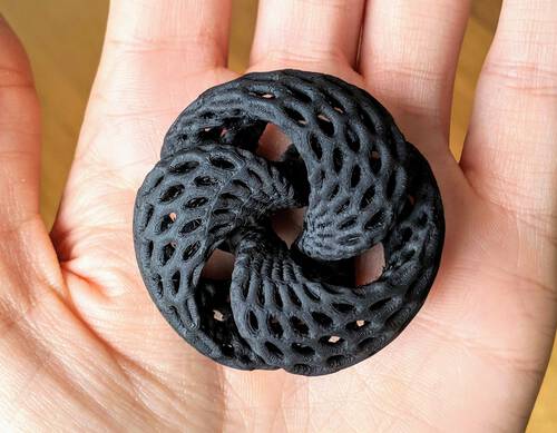
Eventually, the torus had definitely smoothed out a bit and gotten more glossy. Not nearly as glossy as the tiny torus, but noticeable enough. The lines on the inner sides of each opening were still visible, it was mostly the outer sides of the mesh structure that had smoothened.
The bottom was still looking a bit rough, but now more in a “melted rough” kind of way (*^▽^*)ゞ Nevertheless, this torus was now something that I could use as a necklace pendant, since from the front it looked quite nice (as long as you saw it from about 10cm away). So I bought a nice thin black chain for it and am now wearing it on occasion 。^‿^。
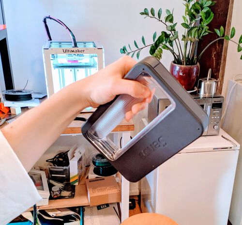
3D Scanning
At the Waag lab there is a 3D Systems Sense scanner (a technology that seems to be discontinued by 3D Systems actually), which is incredible straightforward to use, if not always the easiest to create a scan with I found out.
You plug the Sense Scanner into the computer via USB and start up the Sense software.
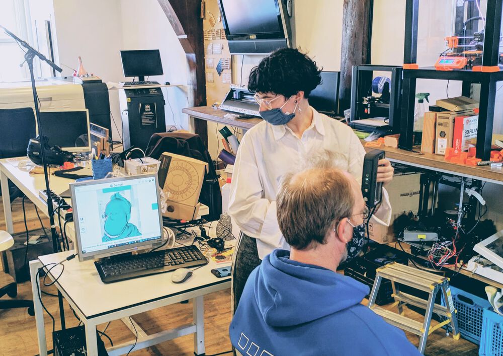
The software itself is quite straightforward with only a few big buttons. You have the option to scan and object, head or body. Select which of those you’re going for, and press the big green SCAN button.
With the Sense scanner you then slowly move around the person/object and let the scanner take hundreds of photos which it stitches together for the scan. On the monitor you’ll see a green mass appear on top of the person/object being scanned.
As a tip, don’t start the scan at the most important section (e.g. the face), because the scan will create a seam at that location. For a head, the back of the head is a good place, because a seam is much less noticeable along the hair.
If the object on the monitor screen is green, things are going well and you can continue to slowly move around the person/object. If it’s red that means that the scanner has lost its tracking and you’ll have to painstakingly try to reposition the scanner so the object and the red image align, so the scanner can hopefully pick it back up again.
![]()
The scanner actually has a lot of trouble scanning smooth objects, because it needs clear visual markers to know what part is what. So a smooth one-colored coffee mug, or an all-white computer mouse are very hard to scan.
Once you’ve managed to go around and have captured all the parts to be scanned (make sure not to forget scanning the lower sides (e.g. holding the scanner low while pointing upward)) press the green Finish button.
The software will take a few seconds to calculate and create the mesh.
You have a few options to adjust this mesh. Such as crop or trim to cut off parts. Or erase to remove very specific sections that were scanned incorrectly. It’s important to press the green apply button after using each specific tool, otherwise it’s lost when you select a different tool.
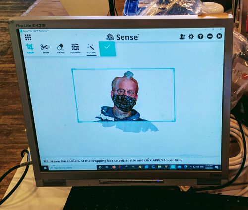
A really handy option is the solidify where the software will fill in all the remaining holes of the mesh. And finally, the color option lets you adjust a few basic settings on to color brightness and saturation.
When you’re ready you can press the big green Finish button to either save the mesh as an .obj (which also keeps the colors in a separate texture .png file) or .stl (which only keeps the mesh).
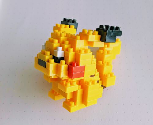
3D Scanning a Pikachu
I brought along a tiny Pikachu statue from home to scan for myself, created from nanoblocks. I wondered how such a blocky structure would look.
However, I quickly found out that the Sense was having a really difficult time to scan such a tiny object. It kept on losing its tracking, and I could only move absurdly slow. The first time I lost tracking after a few seconds and was unable to get it back and aborted the scan to start fresh.
I moved even more slowly on the second try. While having managed to scan one side and slowly moving back to the front to start on the other side (I couldn’t move around it, because the table was in the way) I lost the tracking again, and even after trying to get it back for a solid 5 minutes, it just wouldn’t pick it back up (╥﹏╥)
I didn’t want to hog the scanner any longer and thus pressed Finish and see how much the scanner did manage to pick up. And that was surprisingly quite a lot! It was really only missing a section along the right back side and the right back ear. It’s a little hard to see on the photo below, but you can kind of see how the right eas is missing it’s right-top most section.

I applied the solidify option, and it filled in the missing sections remarkably well! I saved the results both as an .obj file and a .stl file. In the image below-left the filled in sections are visible as white, while the right image shows the side I did manage to get scanned properly.

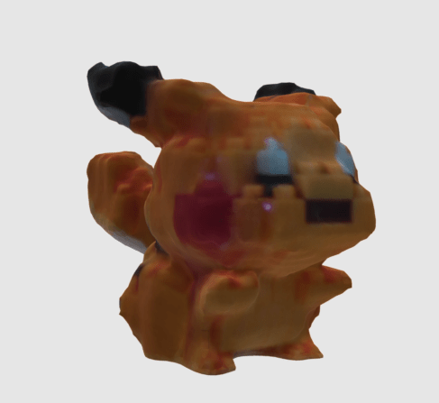
The scan didn’t quite capture the blockiness of the Pikachu statue. It became more a very bubbly surface. But at least it’s definitely recognizable.
While Erwin and Nicole were using the scanner I saw that Erwin’s foot and lower leg came out quite well, but somehow Nicole’s head had two ears along one side, which was quite funny (and a bit creepy ✖_✖ ) to look at. So bigger (rougher) surfaces were definitely easier to scan without losing tracking, but that didn’t mean the resulting mesh was a much better reflection of reality versus smaller objects it seemed.
I have to admit though that the 3D printing held my interest a lot more, so I didn’t experiment with 3D scanning any more than this.
- STL file of the resulting Pikachu mesh | STL file
Reflections
I saw so many mesh structures in the jewelry section of Shapeways (both in metal and plastic) that I figured it must have something that made it straightforward to print. But I guess they use a different kind of printer than an FDM, use PVA to create a good support structure throughout the mesh, or (also highly likely) just have years more experience to make such designs print well in general. I still really like the look of the (voronoi-like) mesh structures though, so I hope to figure it out someday! ᕦ(ò_óˇ)ᕤ
What went wrong
So much went wrong! Never horribly wrong, but more along the “not complying with my expectation” kind of wrong (*^▽^*)ゞ . In general the thing I did most wrong though is to have not thought about the overhang along the top sections and sharp angles in my design. It was still printing, but it was often creating rough surfaces and edges along the bottom. Trying to find a way to make the design work through the usage of the slicer tool and changing settings did teach me a lot though.
But to enumerate some of the printing things that went wrong:
- Forgetting to lay down a brim with my models that have virtually no bottom surface area.
- Putting a support structure within my mesh structure which then could barely be removed (and destroyed a little of the design while doing it).
- Having difficult very sharp edges of > 270° + not setting a random seam location and/or blocking a seam along that edge resulting in horrible rough over-extruded edges.
- Somehow having the bottom part of the support meld together with my torus on the Ultimaker (still not sure why this specifically happened).
- My earring design almost failing in the last 10% when the overhang of the top part became too big. Part of why I’d missed this is because I designed it lying down, but rotated this in the PrusaSlicer after assessing that most of the ellipses would be in a more horizontal orientation (making them easier to print).
- Creating a support tower that was too small and couldn’t be printed through the mesh of my earring.
- Not having a small fan inside my acetone vapor smoothing set-up to circulate the vapors, which might’ve been the reason why the inner section wasn’t smoothed that much.
But at least, apart from one earring that I had to stop after 2 hours because the support was going partially wrong, all the other stopped prints failed on the brim or only a few layers above it, so in total the failed prints didn’t add up to a very long time lost.
What went well
In the end I’d done so many tests that I did create a small jewelry collection, and I’m quite happy with my red earrings 。^‿^。 From a distance they look quite nice and you can’t really see the layers and imperfections.
I’m also happy how nice and smooth the acetone vapor smoothing result made the sides of the torus looked. Perhaps with more testing I could’ve figured out how to make it smooth the entire torus.
What I would do differently
I should pay more attention to the whole of my design, all the angles and overhangs. I would’ve saved myself a lot of time and headaches if I’d gone for a completely different design.
Perhaps I shouldn’t try to make small and delicate designs for FDM printers, things that are meant to look beautiful, because this type of printing just isn’t meant for that (perhaps combining ABS/ASA with acetone vapor smoothing). It’s perhaps more for the “useful and don’t really care how nice it looks” types of objects.
I couldn’t do this differently, but it’s more of a wish: Seeing as how my delicate designs weren’t quite meant to come out beautifully with an FDM 3D printer, I do wish the lab had an SLA (Stereolithography) 3D printer that I could’ve tested with as well (*^▽^*)ゞ Also to see if perhaps that process fits me better (and I’d be willing to deal with the mess) in knowing what printer I might one day purchase for myself.
A multi-material 3D printer would’ve been very interesting to try as well. In that case I could use the water-solvable PVA filament to build up my open meshes with more than enough support.
Wrapping up
Another week in which I invested a lot of time to really make lots of tests. I did really enjoy learning how to work with a 3D printer. But as I mentioned before, perhaps FDM is quite a printer that fits my desired style (*≧▽≦)
. I was very intrigued by the short workshop that Luc from AgriLab gave about working directly with gcode. It seemed like a creative way to work with the heart of 3D printers instead of making it print “a 3D model”.
All Files Together
- The Blender file with all of the torus designs | blend file
- The STL file of the scanned Pikachu mesh | STL file