Eight week assignment is the Embedded programing.In this week I actually understand what is embedded system,different IDE,How to write the program in different environment,what is the importance of reading Data sheet.
Assignment-8
Embedded Programming
OBJECTIVES
Group assignment
- Compare the performance and development workflows for different microcontroller families
- Document your work (in a group or individually)
Individual assignments
- Read the datasheet for the microcontroller you are programming
- Program the board you have made to do something, with as many different programming languages and programming environments as possible.
Learning outcomes
- Identify relevant information in a microcontroller datasheet.
- Implement programming protocols.
About Group Assignment
Task for the group assignmentis to compare the performance and development workflows for different microcontroller families and document it.In group assignment we explored Micro-bit,Raspberry pi and Arduino IDE.For more information of group assignmet click on About Group Assignment.
About Micro:Bit.
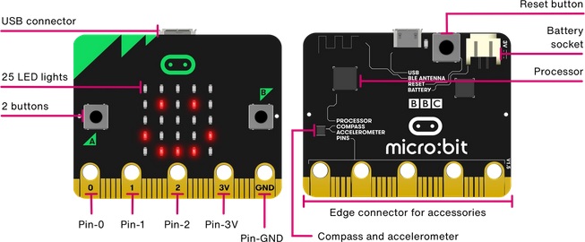
The Micro Bit (also referred to as BBC Micro Bit, stylized as micro:bit) is an open source hardware ARM-based embedded system designed by the BBC for use in computer education in the United Kingdom.
The BBC micro:bit is a pocket-sized computer that introduces you to how software and hardware work together. It has an LED light display, buttons, sensors and many input/output features that you can program and physically interact with. The latest micro:bit adds sound sensing and playback capabilities.(Wikipedia)
Hardware block diagram
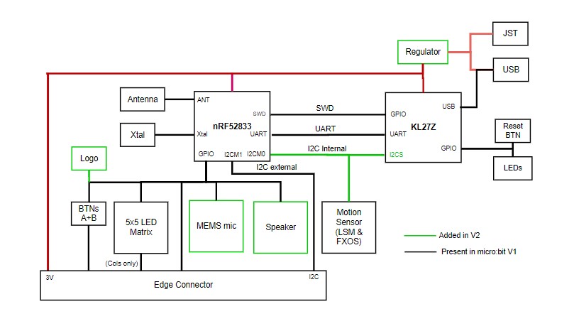
Block Diagram.
Getting Started With the micro:bit Hardware
The micro:bit is a Single Board Computer (SBC) that contains an application processor with a variety of on-chip peripherals.Other peripherals are connected to this chip.An interface processor is connected to the application processor and manages communications via the USB interface, including the drag-and-drop code flashing process. The interface processor does not connect to any of the micro:bit peripherals.
For more details go through the link.
About Raspberry Pi.
The Raspberry Pi is a low cost, credit-card sized computer that plugs into a computer monitor or TV, and uses a standard keyboard and mouse. It is a capable little device that enables people of all ages to explore computing, and to learn how to program in languages like Scratch and Python. It’s capable of doing everything you’d expect a desktop computer to do, from browsing the internet and playing high-definition video, to making spreadsheets, word-processing, and playing games.(Wikipedia)
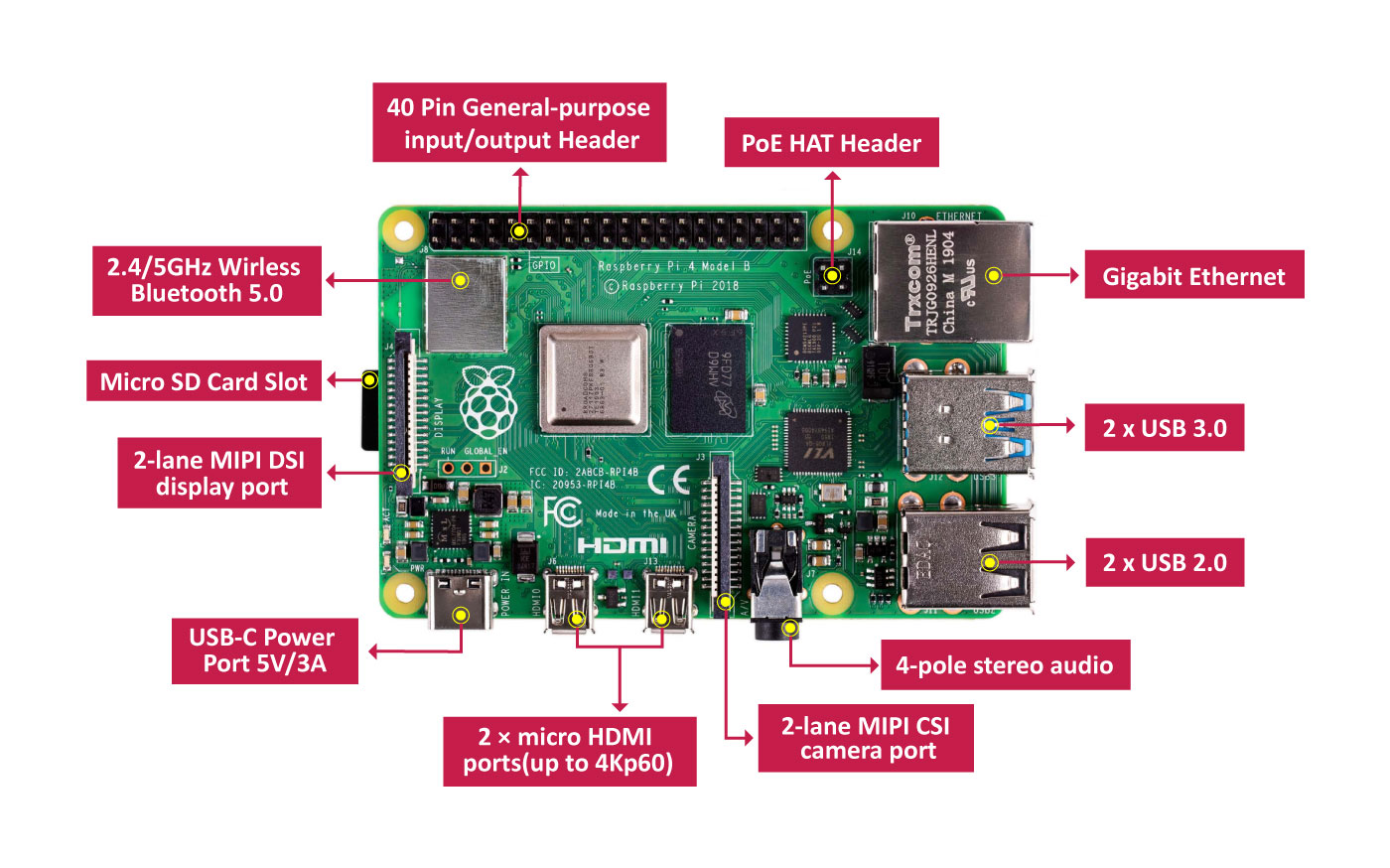
Raspberry Pi board.
Features.
A powerful feature of the Raspberry Pi is the row of GPIO (general-purpose input/output) pins along the top edge of the board. A 40-pin GPIO header is found on all current Raspberry Pi boards (unpopulated on Pi Zero and Pi Zero W). Prior to the Pi 1 Model B+ (2014), boards comprised a shorter 26-pin header.
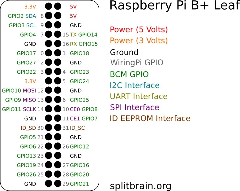
Pin Diagram.
Any of the GPIO pins can be designated (in software) as an input or output pin and used for a wide range of purposes.
Note that the numbering of the GPIO pins is not in numerical order; GPIO pins 0 and 1 are present on the board (physical pins 27 and 28) but are reserved for advanced use (see below).
- Voltages : Two 5V pins and two 3V3 pins are present on the board, as well as a number of ground pins (0V), which are unconfigurable. The remaining pins are all general purpose 3V3 pins, meaning outputs are set to 3V3 and inputs are 3V3-tolerant.
- Outputs : A GPIO pin designated as an output pin can be set to high (3V3) or low (0V).
- Inputs : A GPIO pin designated as an input pin can be read as high (3V3) or low (0V). This is made easier with the use of internal pull-up or pull-down resistors. Pins GPIO2 and GPIO3 have fixed pull-up resistors, but for other pins this can be configured in software.
- More : As well as simple input and output devices, the GPIO pins can be used with a variety of alternative functions, some are available on all pins, others on specific pins.
- Software PWM available on all pins
- Hardware PWM available on GPIO12, GPIO13, GPIO18, GPIO19
PWM (pulse-width modulation)
- SPI0: MOSI (GPIO10); MISO (GPIO9); SCLK (GPIO11); CE0 (GPIO8), CE1 (GPIO7)
- SPI1: MOSI (GPIO20); MISO (GPIO19); SCLK (GPIO21); CE0 (GPIO18); CE1 (GPIO17); CE2 (GPIO16)
SPI
- Data: (GPIO2); Clock (GPIO3)
- EEPROM Data: (GPIO0); EEPROM Clock (GPIO1)
I2C
- TX (GPIO14); RX (GPIO15)
Serial
For more details click on Interactive pinout diagram. (Source:www.raspberrypi.org)
Specifications.
- Broadcom BCM2711, Quad core Cortex-A72 (ARM v8) 64-bit SoC @ 1.5GHz
- 2GB, 4GB or 8GB LPDDR4-3200 SDRAM (depending on model)
- 2.4 GHz and 5.0 GHz IEEE 802.11ac wireless, Bluetooth 5.0, BLE
- Gigabit Ethernet
- 2 USB 3.0 ports; 2 USB 2.0 ports.
- Raspberry Pi standard 40 pin GPIO header (fully backwards compatible with previous boards)
- 2 × micro-HDMI ports (up to 4kp60 supported)
- 2-lane MIPI DSI display port
- 2-lane MIPI CSI camera port
- 4-pole stereo audio and composite video port
- H.265 (4kp60 decode), H264 (1080p60 decode, 1080p30 encode)
- OpenGL ES 3.0 graphics
- Micro-SD card slot for loading operating system and data storage
- 5V DC via USB-C connector (minimum 3A*)
- 5V DC via GPIO header (minimum 3A*)
- Power over Ethernet (PoE) enabled (requires separate PoE HAT)
- Operating temperature: 0 – 50 degrees C ambient
- Note- A good quality 2.5A power supply can be used if downstream USB peripherals consume less than 500mA in total.(Source:www.raspberrypi.org)
The specifications of Raspberry Pi are given below.
Individual assignment on Embedded Programming
In this week as per given task we have to read the data sheet for the microcontroller. I have used Attiny 45 , read its datasheet also program it for blinking LED using different programming language like Arduino,embedded C and program the Helloworld board.The work flow of the assignment is as follows
- About Embedded System
- About Architecture
- AVR microcontrollers
- Data sheet and its need
- About Attiny 45 Microcontroller
- Programming with Arduino IDE
About Embedded System
As its name suggests, Embedded means something that is attached to another thing. An embedded system can be thought of as a computer hardware system having software embedded in it. An embedded system can be an independent system or it can be a part of a large system. An embedded system is a microcontroller or microprocessor based system which is designed to perform a specific task. For example, a fire alarm is an embedded system; it will sense only smoke.
About Architecture
Typical embedded system mainly has two parts i.e., embedded hardware and embedded software.Embedded hardwares are based around microprocessors and microcontrollers, also include memory, bus, Input/Output, Controller, where as embedded software includes embedded operating systems, different applications and device drivers. Basically these two types of architecture i.e., Harvard architecture and Von Neumann architecture are used in embedded systems.

Von Neumann architecture
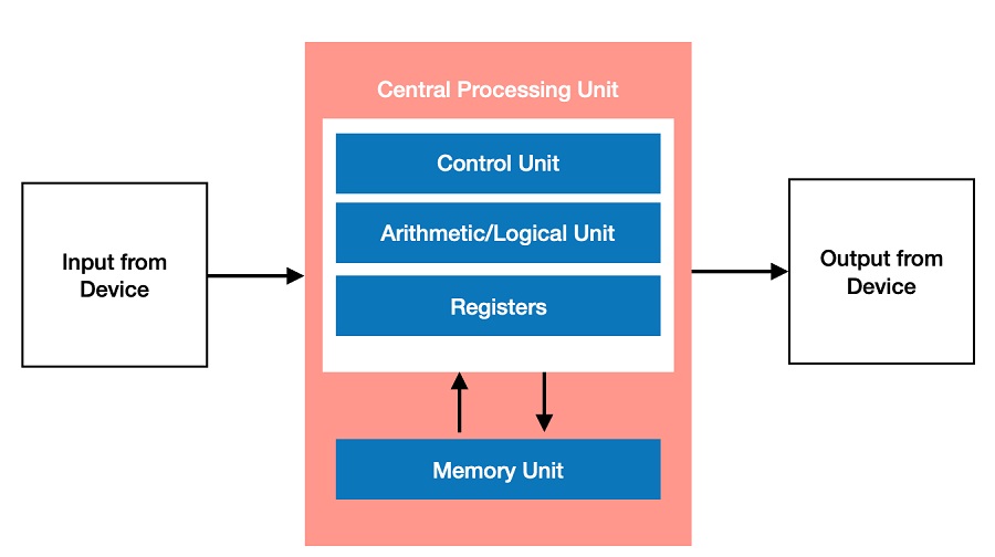
Von Neumann Architecture is a digital computer architecture whose design is based on the concept of stored program computers where program data and instruction data are stored in the same memory. This architecture was designed by the famous mathematician and physicist John Von Neumann in 1945.
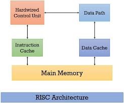
Harvard architecture
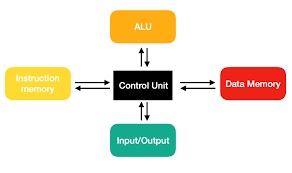
Harvard Architecture is the digital computer architecture whose design is based on the concept where there are separate storage and separate buses (signal path) for instruction and data. It was basically developed to overcome the bottleneck of Von Neumann Architecture.
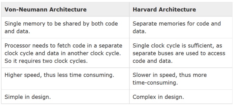
Von Neumann architecture Vs Harvard architecture
What is Microprocessor ?
Microprocessor is a controlling unit of a micro-computer, fabricated on a small chip capable of performing ALU (Arithmetic Logical Unit) operations and communicating with the other devices connected to it. Microprocessor consists of an ALU, register array, and a control unit.
What is Microcontroller?
A microcontroller (MCU for microcontroller unit) is a small computer on a single metal-oxide-semiconductor (MOS) integrated circuit (IC) chip. A microcontroller contains one or more CPUs (processor cores) along with memory and programmable input/output peripherals.
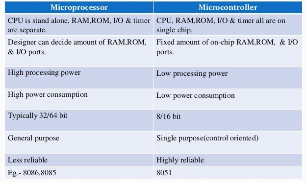
Microprocessor Vs Microcontroller
What is RISC?
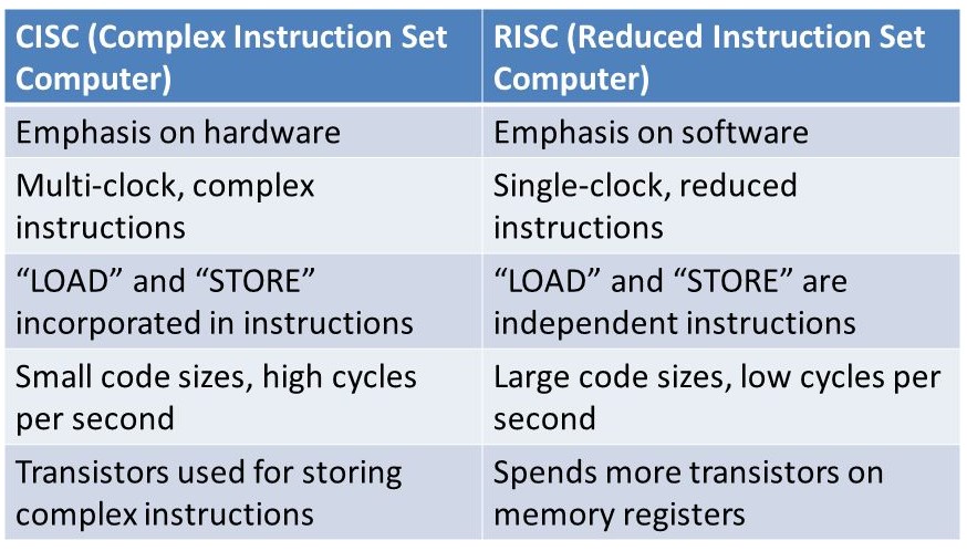
RISC, or Reduced Instruction Set Computer. is a type of microprocessor architecture that utilizes a small, highly-optimized set of instructions, rather than a more specialized set of instructions often found in other types of architectures.
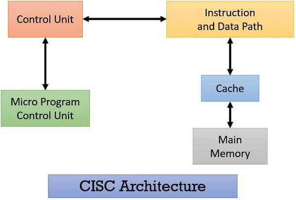
What is CISC?
CISC stands for "Complex Instruction Set Computing." This is a type of microprocessor design. The CISC architecture contains a large set of computer instructions that range from very simple to very complex and specialized.
CISC Vs RISC
AVR microcontrollers
AVR is a family of microcontrollers developed since 1996 by Atmel, acquired by Microchip Technology in 2016. These are modified Harvard architecture 8-bit RISC single-chip microcontrollers. AVR was one of the first microcontroller families to use on-chip flash memory for program storage, as opposed to one-time programmable ROM, EPROM, or EEPROM used by other microcontrollers at the time. AVR microcontrollers find many applications as embedded systems. They are especially common in hobbyist and educational embedded applications, popularized by their inclusion in many of the Arduino line of open hardware development boards.
- tinyAVR (ATtiny)
- megaAVR (ATmega)
- Xmega (ATxmega)
The AVR family is classified as follows
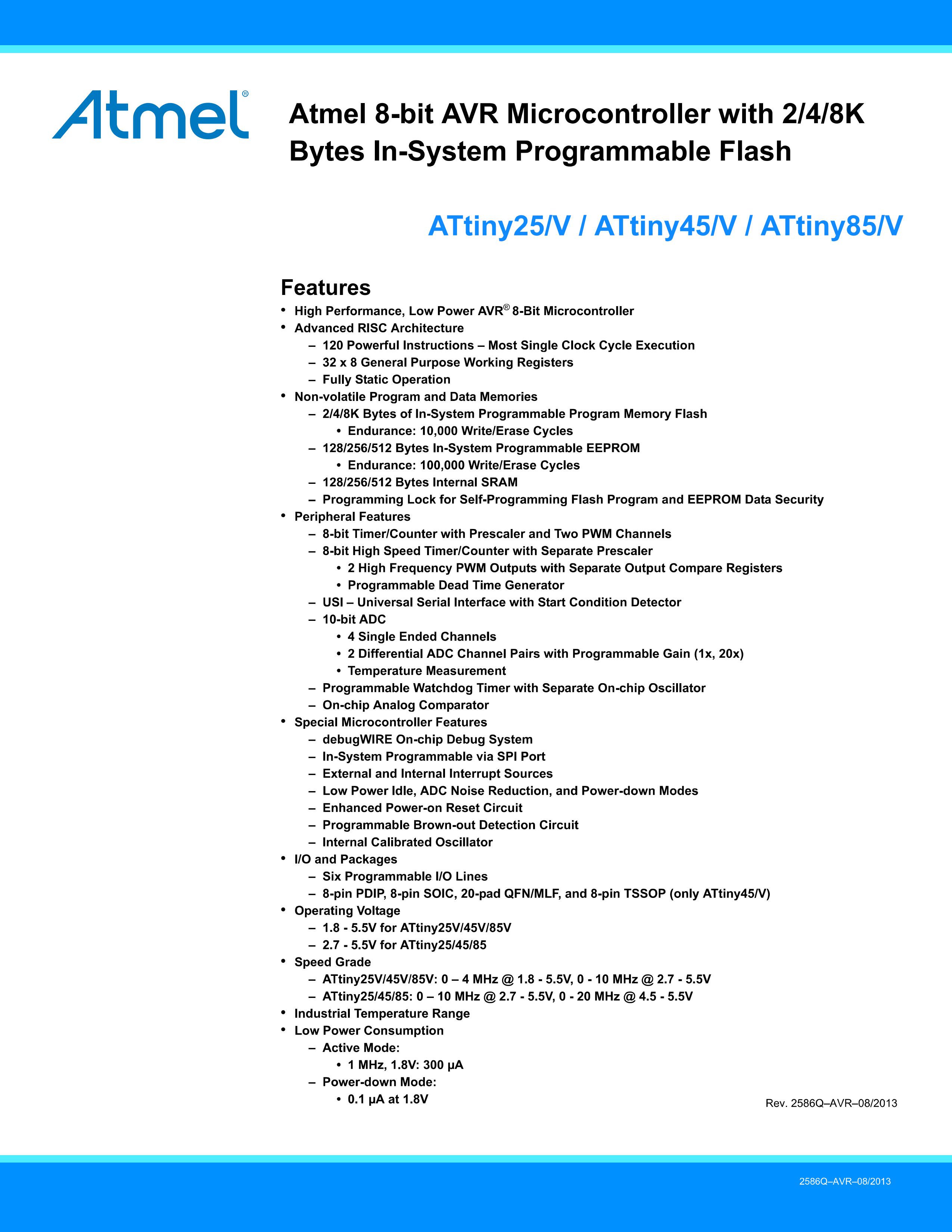
Data sheet and its need
Datasheets are instruction manuals for electronic components. They (hopefully) explain exactly what a component does and how to use it. Unfortunately these documents are usually written by engineers for other engineers, and as such they can often be difficult to read, especially for newcomers. Nevertheless, datasheets are still the best place to find the details you need to design a circuit or get one working. I have used Attiny 45 in my Helloworld board.The datasheet of ATtiny 45 is given below.
About Attiny 45 Microcontroller
ATtiny45 is a high-performance, low-power Atmel 8-bit AVR RISC-based microcontroller combines 4KB ISP flash memory, 256-Byte EEPROM, 256B SRAM, 6 general purpose I/O lines, 32 general purpose working registers, one 8-bit timer/counter with compare modes, one 8-bit high speed timer/counter, USI, internal and external Interrupts, 4-channel 10-bit Analog to Digital converter, programmable watchdog timer with internal oscillator, three software selectable power saving modes, and debugWIRE for on-chip debugging. The device achieves a throughput of 20 MIPS at 20 MHz and operates between 2.7-5.5 volts.By executing powerful instructions in a single clock cycle, the device achieves throughputs approaching 1 MIPS per MHz, balancing power consumption and processing speed.
Data Sheet ATtiny 45
- Flash (Kbytes) : 4 Kbytes
- Pin Count : 8
- Max. Operating Freq. (MHz) : 20 MHz
- CPU : 8-bit AVR
- Number of Touch Channels : 3
- Max I/O Pins : 6
- Ext Interrupts : 6
- USB Interface : No
- Operating Voltage : 2.7 - 5.5V for ATtiny25/45/85
- Speed Grade –ATtiny25/45/85 0 – 10 MHz @ 2.7 - 5.5V , 0 - 20 MHz @ 4.5 - 5.5V
- Low Power Consumption Active Mode: 1 MHz, 1.8V : 300 µA – Power-down Mode: 0.1 µA at 1.8V
Features of ATtiny45 Microcontroller
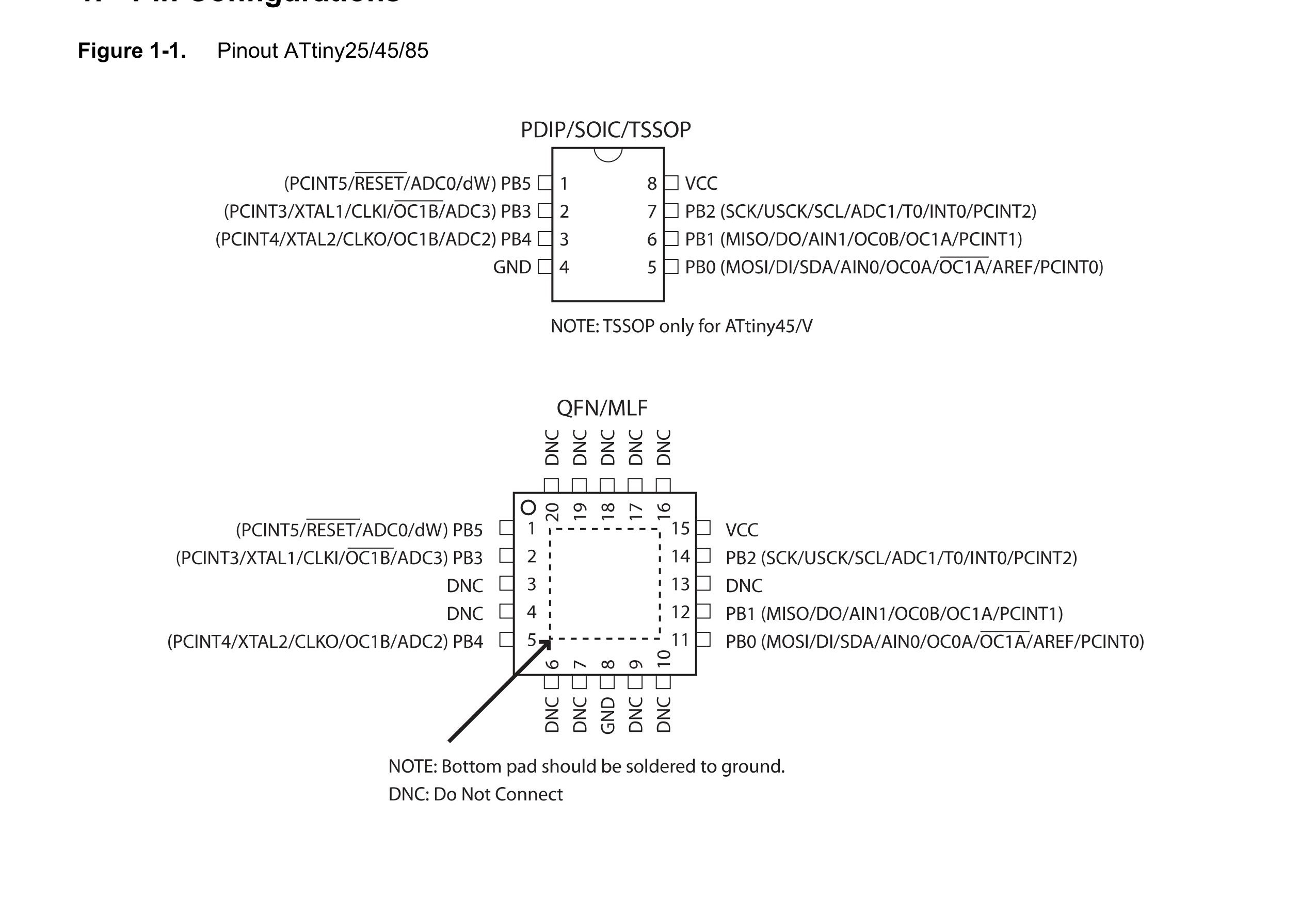
Pin diagram of ATtiny 45
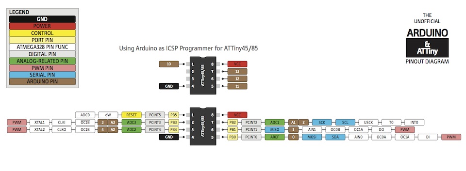
Arduino Pinout of ATtiny 45
- VCC : Supply voltage.
- GND : Ground.
- Port B : (PB5:PB0) Port B is a 6-bit bi-directional I/O port with internal pull-up resistors (selected for each bit). The Port B output buffers have symmetrical drive characteristics with both high sink and source capability. As inputs, Port B pins that are externally pulled low will source current if the pull-up resistors are activated. The Port B pins are tri-stated when a reset condition becomes active, even if the clock is not running.
- RESET: Reset input. A low level on this pin for longer than the minimum pulse length will generate a reset, even if the clock is not running and provided the reset pin has not been disabled. Shorter pulses are not guaranteed to generate a reset. The reset pin can also be used as a (weak) I/O pin.
Pin description of ATtiny 45
In my helloworld board ,i had conneect the led to the physical pin 2.This is the actually PB-3 of IC.PB is a 6-bit bi-directional I/O port with internal pull-up resistors.so inststed of using pin 2 I used PB-3 in my programming code.
Block Diagram ATtiny 45
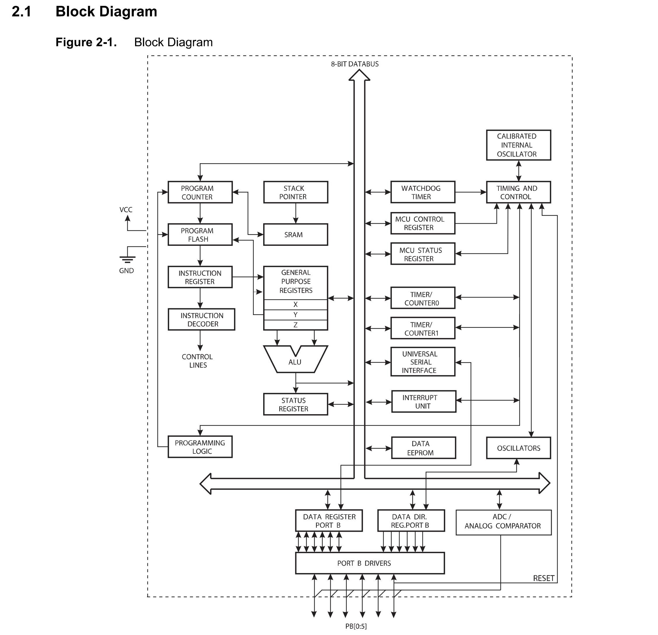
The AVR core combines a rich instruction set with 32 general purpose working registers. All 32 registers are directly connected to the Arithmetic Logic Unit (ALU), allowing two independent registers to be accessed in one single instruction executed in one clock cycle. The resulting architecture is more code efficient while achieving throughputs up to ten times faster than conventional CISC microcontrollers.
Programming with Arduino IDE
About Arduino
Arduino is an open-source electronics platform based on easy-to-use hardware and software. Arduino boards are able to read inputs - light on a sensor, a finger on a button, or a Twitter message - and turn it into an output - activating a motor, turning on an LED, publishing something online. You can tell your board what to do by sending a set of instructions to the microcontroller on the board. To do so you use the Arduino programming language (based on Wiring), and the Arduino Software (IDE), based on Processing.
About Arduino IDE
The Arduino Integrated Development Environment - or Arduino Software (IDE) - contains a text editor for writing code, a message area, a text console, a toolbar with buttons for common functions and a series of menus. It connects to the Arduino and Genuino hardware to upload programs and communicate with them.It is a cross-platform application (for Windows, macOS, Linux) that is written in functions from 'C' and 'C++'. It is used to write and upload programs to not only the Arduino board but also the various other boards with different micro-controller like Atmega328p, attiny44, 45, ESP32...etc.
Opening window of Arduino IDE
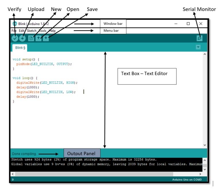
Details of program in 'Arduino IDE
Before writting the program we should select the type of micro-controller we are using in our board. Here I have choose the micro-controller Atatiny45 from the list of tiny family.ATtiny mcus are not support by the Arduino IDE by default. We need to add the library of ATtiny45 into the environment.The process of adding ATtiny45 library is already given in the Electronic Production week.
Goto the simple Blinking code which is available in the Example section of Arduino IDE. This example programs become helpful for the beginner like me. In the Electronics designing week I have program my Hellow world board by modifying the program.
LED Blink code
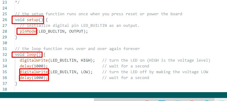
- Void : Void datatype is a keyword used for function declarations.
- voidsetup(): The voidsetup() function is called when a sketch starts. Use it to initialize variables, pin modes, start using libraries, etc. The setup() function will only run once, after each powerup or reset of the Arduino board.
- pinMode : Configures the specified pin to behave either as an input or an output.
- voidloop(): After creating a setup() function, which initializes and sets the initial values, the loop() function does precisely what its name suggests, and loops consecutively, allowing your program to change and respond.
- Digitalwrite() : Write a HIGH or a LOW value to a digital pin.
- Delay : Pauses the program for the amount of time (in milliseconds) specified as parameter. (There are 1000 milliseconds in a second.)
- break : break is used to exit from a for, while or do…while loop, bypassing the normal loop condition. It is also used to exit from a switch case statement
- (//): These instructions are written by the programmer. This will help to understand the command line of the program
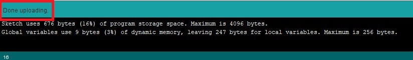
I had made some modification in the in the Blinking LED code, verified it and compiling it. The compling process can be seen in the bottom of window.Once the colpilation is done, click on uopaoalding button the uploading process can be seen in the bottom of the window.After uploading the it shows the message Done uploading.
Compiling the program

Uploading the program
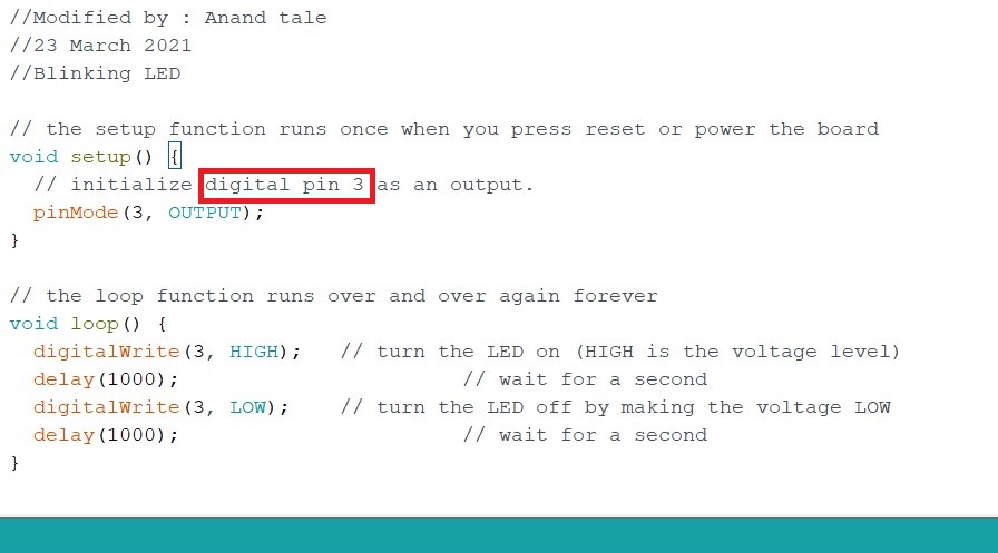
Source code of LED Blink
In following LED blink code I have trying to change output pin only.
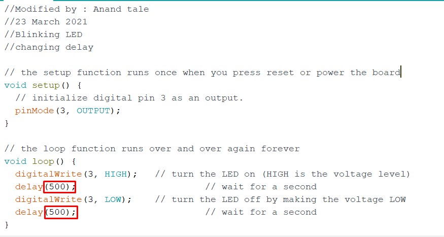
In following LED blink code I have trying to change output pin as well as delay.
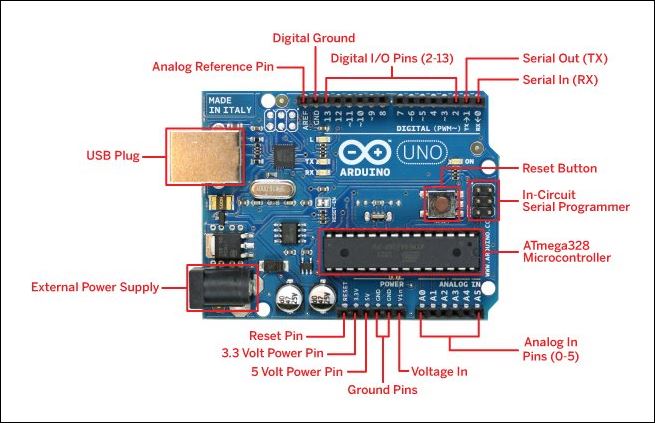
About Arduino Uno Board
The Arduino Uno is an open-source microcontroller board based on the Microchip ATmega328P microcontroller and developed by Arduino.cc. ... The board has 14 digital I/O pins (six capable of PWM output), 6 analog I/O pins, and is programmable with the Arduino IDE (Integrated Development Environment), via a type B USB cable.
Arduino Uno pin diagram
- The operating voltage is 5V.
- The recommended input voltage will range from 7v to 12V.
- The input voltage ranges from 6v to 20V.
- Digital input/output pins are 14.
- Analog i/p pins are 6.
- DC Current for each input/output pin is 40 mA.
- DC Current for 3.3V Pin is 50 mA.
- Flash Memory is 32 KB.
- SRAM is 2 KB
- EEPROM is 1 KB.
- CLK Speed is 16 MHz.
The features of Arduino Uno ATmega328 includes the following.
Before uploadind the LED blinking proram in my helloworld board I treid on Arduino Uno board with pin 3 as 0utput pin.
After sucessfully uploaing the program on Arduino Uno board, i have uploaded LED blinking program on my Helloworld board.
Hero Video.
programming with Embedded C
About Embedded C
Embedded C is a generic term given to a programming language written in C, which is associated with a particular hardware architecture. Embedded C is an extension to the C language with some additional header files. These header files may change from controller to controller.
About Embedded C Programming
In every embedded system based projects, Embedded C programming plays a key role to make the microcontroller run & perform the preferred actions. At present, we normally utilize several electronic devices like mobile phones, washing machines, security systems, refrigerators, digital cameras, etc. The controlling of these embedded devices can be done with the help of an embedded C program. For example in a digital camera, if we press a camera button to capture a photo then the microcontroller will execute the required function to click the image as well as to store it.
Features of Embedded C Programming
- It is only the extension of C language and mothing more.
- It has source code format that depends upon the kind of microcontroller or microprocessor that have been being used.
- Through embedded c high level optimization can done.
- It is used in microprocessor or microcontroller applications.
- It has limited resources for used, mean the embedded system have only memory location.
- In embedded c constraints runs on real time and output is not available at operating system.
- It only supports the adequate processor or controller.
- In embedded c only pre-define program can run.
- It requires a compiler of embedded c, which have the compatibility with all the embedded system resources.
- Some of the examples of embedded system c application are digital camera, DVD and digital TV etc.
- The major advantage of embedded c is its coding speed and size is very simple and easy to understand.
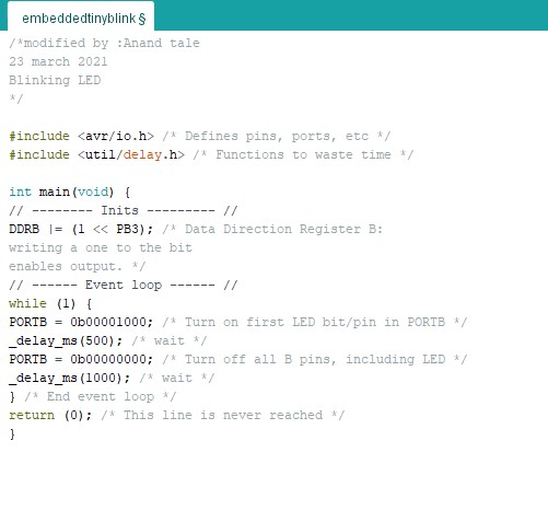
Embedded C Program
I have write the LED blink code in embedded c with the referece of book "Make:AVR programming" by Elliot Williams.In my Hello World Board, I have connected LED to physical pin 2 i.e. PB3. So first step is to define PB3 as digital Output.Modified the Date Direction resistor(DDR) for this pin.
- The ATtiny 45 has set of port B. For port B(PB0-PB5) we use the DDRB command. To set all pins of PORT B as output we should write : DDRB =0xFF or DDRB =0b11111111. Where:
- "1" represents output.
- "0x" represents hexadecimal value.
- "0b" represents binary value.
- #include (avr/io.h) : Import header files required for AVR microcontrollers.
- #include (util/delay.h) :Import header flie required for delay function.
- To set port as high we write PORTB = 0b00001000
- To set any port as low we write PORTB=0b00000000
- delay is use to set state of LED.
Embedded C code for Blink LED
Uploaded the embedded c code for LED blicking on the Arduino uno board as PB3 as output pin.
Uploaded the embedded c code on Helloworld board.
Hero Video.
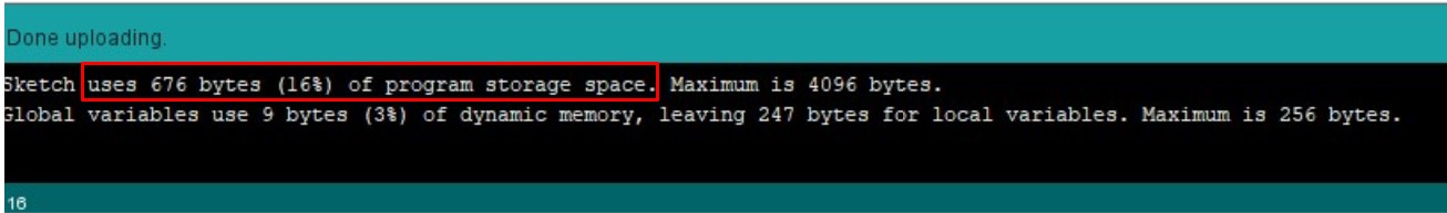
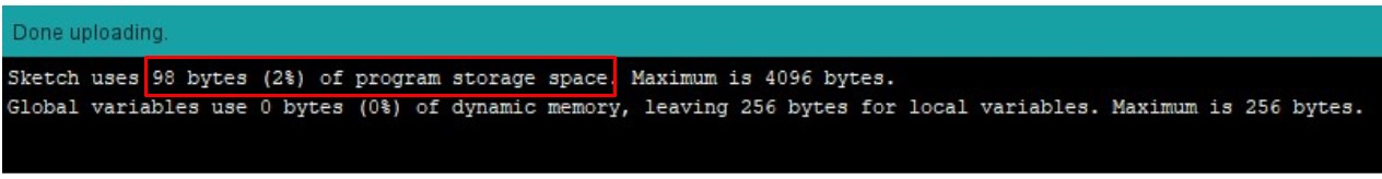
Observation
Uploaded Arduino Program
Uploaded Embedded C program
Learning Outcomes
- In this week I introduced with Embedded system.
- I understand how to read datasheet and why it is necessory.
- Read the the data sheet of ATtity 45 microcomtroller.
- write LED blinking program in Ardunio and embedded c programming language with Arduino IDE.
- program the Arduino Uno board and Helloworld board.
Downloads
SAMS-Smart Azolla Multiplier System by Anand S. Tale is licensed under CC BY-SA 4.0![]()
![]()
![]()