In sixth week we have to study different electronic equipments for testing different paraments in a group assignment. In the electronic production week we have studied the different factors milling pcb on SRM-20. This week we have implemented for designing and milling the hello world board and try to program it.
Hero Shot.
Assignment-6
Electronics Design
OBJECTIVES
Group assignment
- Use the test equipment in your lab to observe the operation of a microcontroller circuit board (in minimum, check operating voltage on the board with multimeter or voltmeter and use oscilloscope to check noise of operating voltage and interpret a data signal)
- Document your work (in a group or individually)
Individual assignments
- Redraw one of the echo hello-world boards or something equivalent, add (at least) a button and LED (with current-limiting resistor) or equivalent input and output, check the design rules, make it, test it.
Learning outcomes
- Select and use software for circuit board design
- Demonstrate workflows used in circuit board design
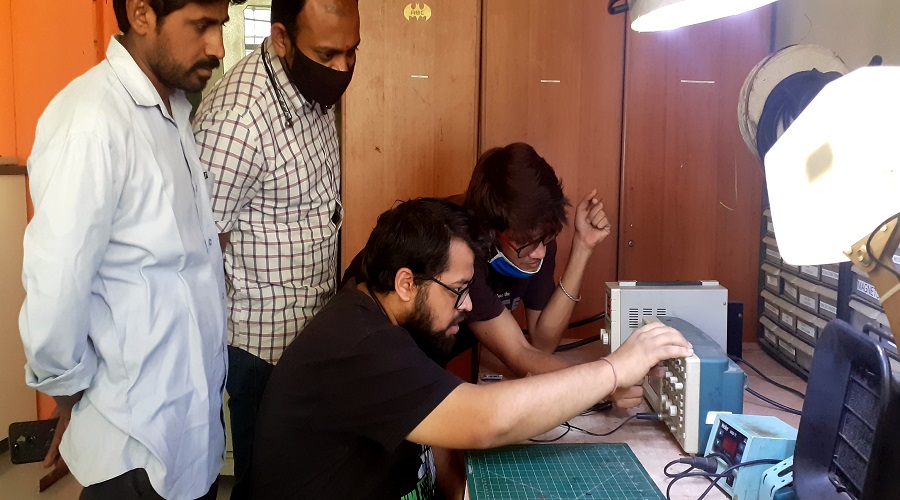
About Group Assignment
In this week assignment we were used different electronic testing instruments like Mutimeter, regulated power supply, DSO etc.By using multimeter we checked the continuity,capacitance, voltage , current. Regulated power supply were provide control voltage . A digital storage oscilloscope (DSO) is an oscilloscope which stores and analyses the input signal digitally rather than using analog techniques. It is now the most common type of oscilloscope in use because of the advanced trigger, storage, display and measurement features like sigal frequency,magnetuide,RMS vale,period etc,which it typically provides.For details about click on About Group Assignment
Set the paramenters of DSO
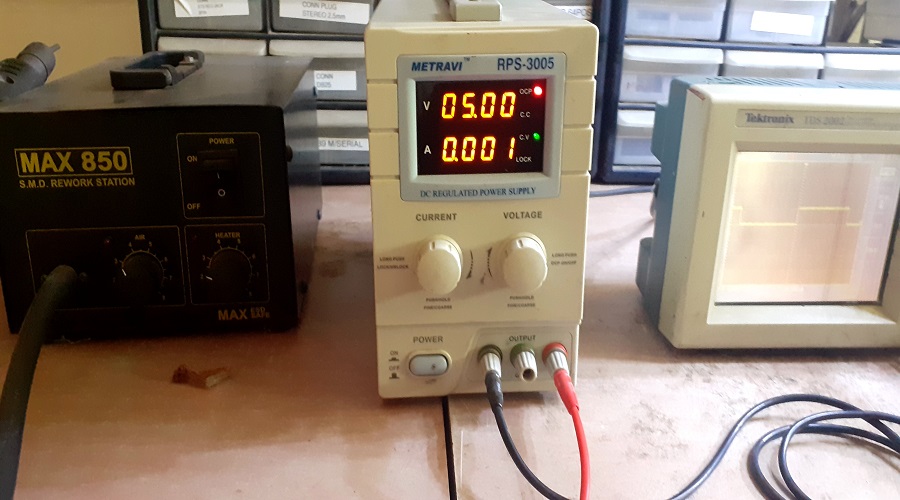
Regulated Power supply
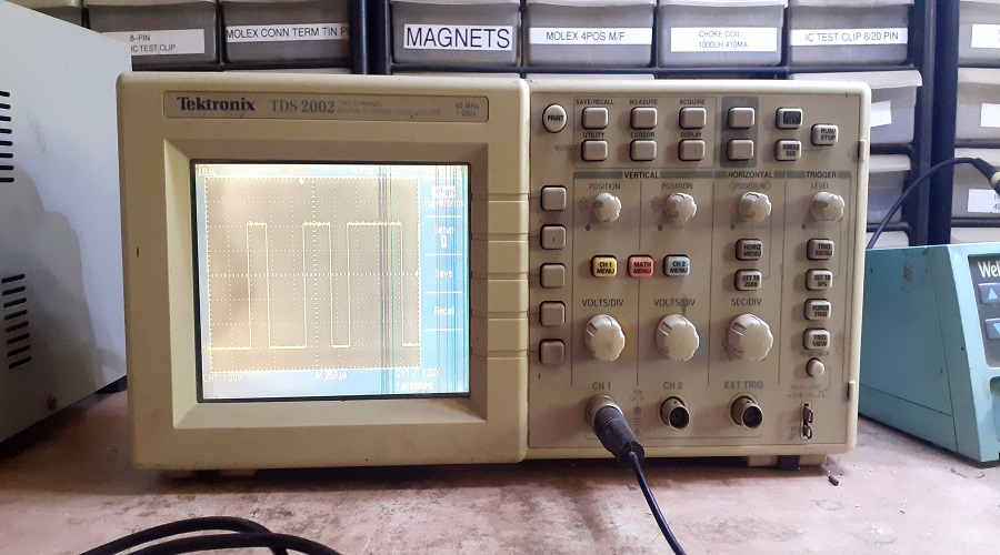
DSO
Individual assignment on Electronics Design
In the individual assignment we have to design helloworld circuit by our own using circuit design software "EAGLE" (Easily Applicable Graphical Layout Editor). Eagle is easily accessible and user friendly software. Eagle has flexible and expandable EDA (Electronic Design Automation) schematic capture, PCB layout, autorouter and CAM programing features.the design circuit program by previously designed FABISP.
- Types of Electronics Devices
- About ATtiny 45
- About Eagle Software.
- Design PCB using Eagle Software.
- Milling PCB by SRM 20
- Soldering PCB
- Programming PCB through Arduino
In this assignments going through following steps
Types of Electronics Devices
Electronic elements that make up a circuit are connected together by conductors to form a complete circuit.
- Active components
- Passive components
Active components
An active component is an electronic component which supplies energy to a circuit.
- Voltage sources
- Current sources
- Generators (such as alternators and DC generators)
- All different types of transistors (such as bipolar junction transistors, MOSFETS, FETs, and JFET)
Common examples of active components include:
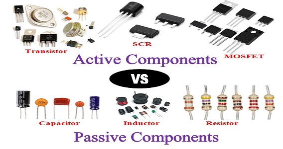
Passive components
A passive component is an electronic component which can only receive energy, which it can either dissipate, absorb or store it in an electric field or a magnetic field. Passive elements do not need any form of electrical power to operate.As the name ‘passive’ suggests – passive devices do not provide gain or amplification. Passive components cannot amplify, oscillate, or generate an electrical signal.
- Resistors
- Inductors
- Capacitors
- Transformers
Common examples of passive components include:
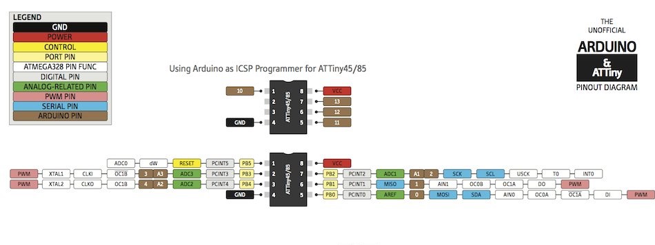
About Attiny45
ATtiny45 is a high-performance, low-power Atmel 8-bit AVR RISC-based microcontroller combines 4KB ISP flash memory, 256-Byte EEPROM, 256B SRAM, 6 general purpose I/O lines, 32 general purpose working registers, one 8-bit timer/counter with compare modes, one 8-bit high speed timer/counter, USI, internal and external Interrupts, 4-channel 10-bit Analog to Digital converter, programmable watchdog timer with internal oscillator, three software selectable power saving modes, and debug WIRE for on-chip debugging. The device achieves a throughput of 20 MIPS at 20 MHz and operates between 2.7-5.5 volts.By executing powerful instructions in a single clock cycle, the device achieves throughputs approaching 1 MIPS per MHz, balancing power consumption and processing speed.
- Flash (Kbytes):4 Kbytes
- Pin Count:8
- Max. Operating Freq. (MHz):20 MHz
- CPU:8-bit AVR
- Number of Touch Channels:3
- Max I/O Pins:6
- Ext Interrupts:6
- USB Interface:No
Features of ATtiny-45 Micro-controller:
Pin out Attiny45
About Eagle Software
EAGLE is a scriptable electronic design automation (EDA) application with schematic capture, printed circuit board (PCB) layout, auto-router and computer-aided manufacturing (CAM) features. EAGLE stands for Easily Applicable Graphical Layout Editor (German: Einfach Anzuwendender Grafischer Layout-Editor) and is developed by CadSoft Computer GmbH. The company was acquired by Autodesk Inc. in 2016(wikipedia)
More about Eagle
Designing PCB through Eagle Software
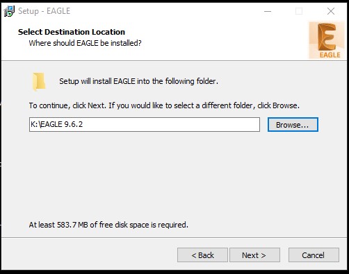
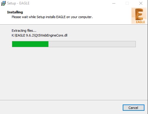
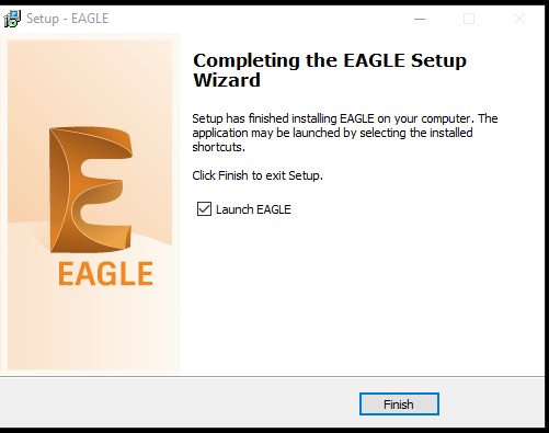
Step1.Down loding Eagle 9.6.2 software in the operating system
Step2. Adding Eagle libraries
Add the 'Fab library'(eagl_fab) in the Eagle interface. by adding this library we get the list of different components we requires in circuit designing.
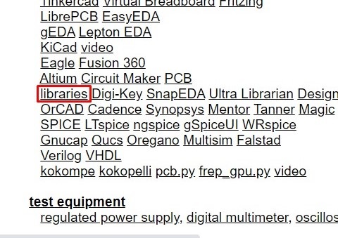
- Goto the Fabacademy2021 schedule,click on Electronic Design click on libraries.
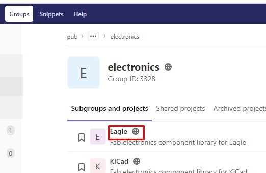
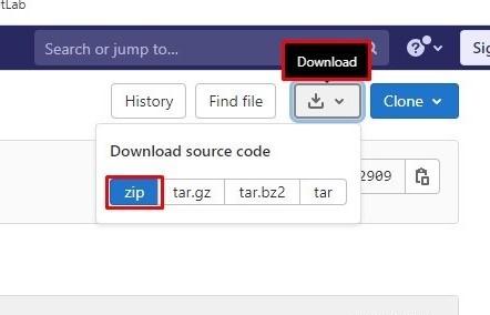
- In gitbash Click on Eagle electronics components library.Goto download zip folder.Add the Fab.lbr file in Eagle bibrary.
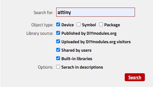
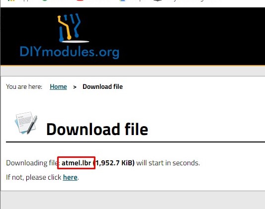
- For atmel library goto DIYmodules.org.goto search engine for Eagle libraries. Search for ATtiny and download atmel.lbr.Add in Eagle library
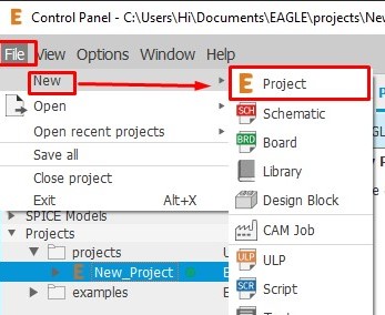
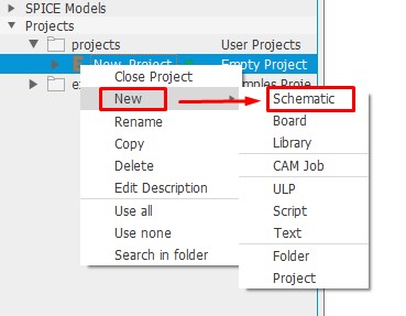
Step3.Open the Eagle goto file select project new Schematics.
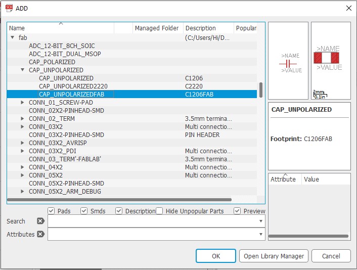
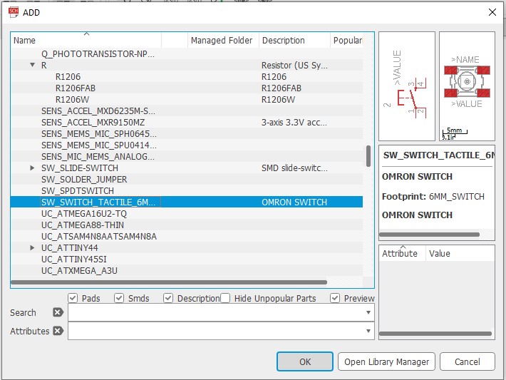
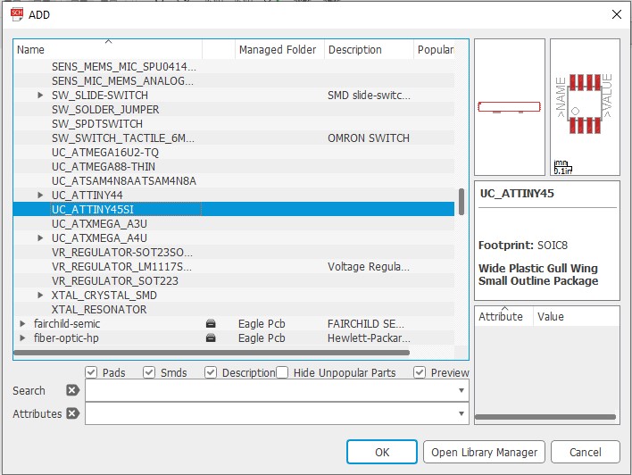
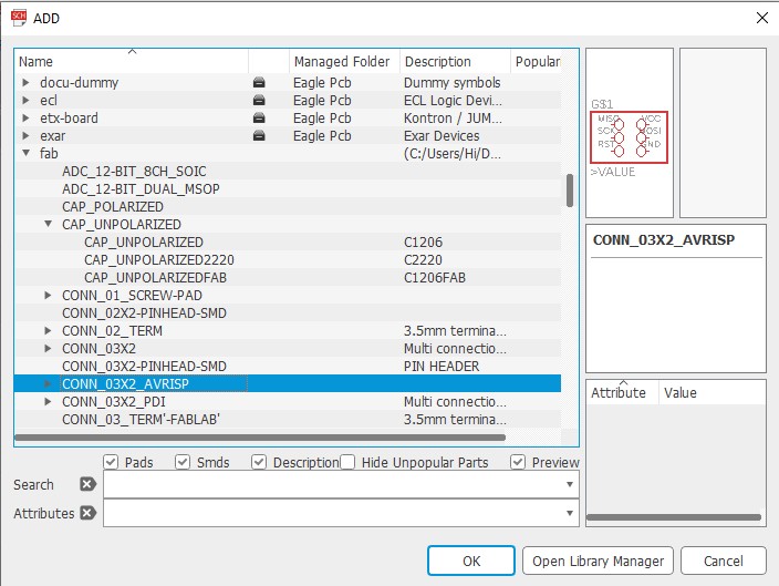
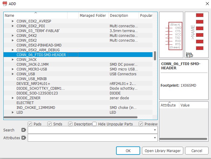
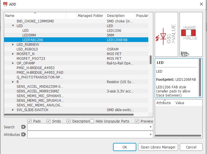
Step4.Adding components in new schematics.
- Goto add components. Click on fab library and select component have to add in schematics
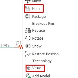
Step4. Name and apply the value to the components.
- Right click on the plus sign on the compoent and apply its name and value
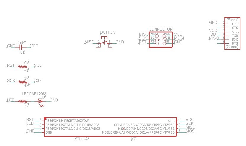
Step5. All the components add in the schematics as shown in the image.With ATtiny 45 added one resistor,LED and single push button.
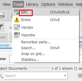
Step6.check the errors in schematics before switch board.
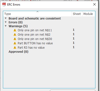
- Goto the Tools click on ERC(Electrical Rule check).which shows the details of Errors and warnings.
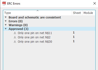
- Check all the warning and fixed it.
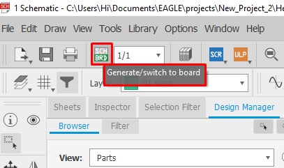
Step7.Now Generate /switch to board.
- Goto the top of interface click on SCH/BRD(switch to board ).opening a Eagle second window.
- This will begin the process of generating a PCB layout based on the components and wiring in your schematic.
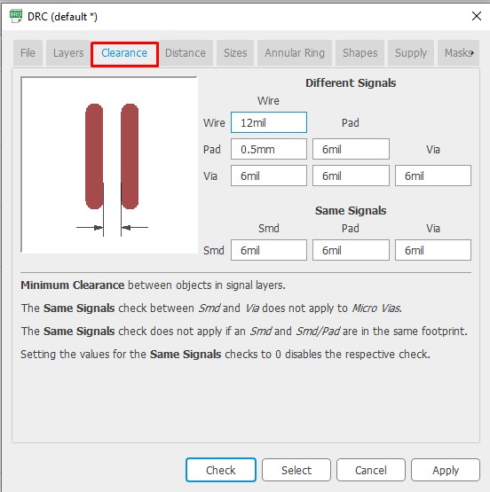
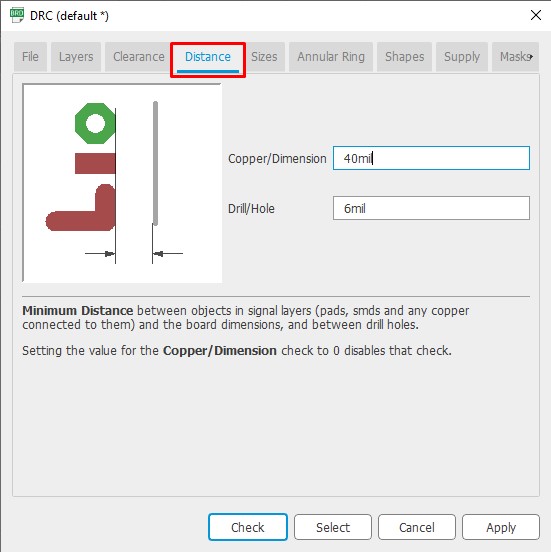
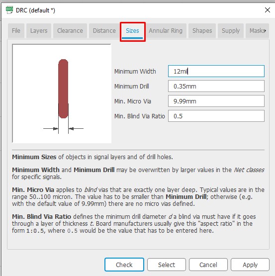
Step8.Check DRC in board
- Before generating the PCB board design go through the DRC.
- DRC means Design rule check is the option provided in the eagle to ckeck the trace width in our board design.
- This will help us to design the board by considering all manufacturing limitations.
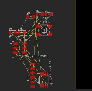
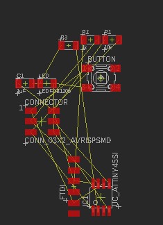
Step9.Placing components in PCB layout area
Placing all the components on the layout such that the minimum wires cross each other.We can route the PCB by Auto router or by Route airwire (Hand Routing).i have tried for both.
- For auto routing arrange all the components on the layout.
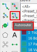
- Click the Auto router.
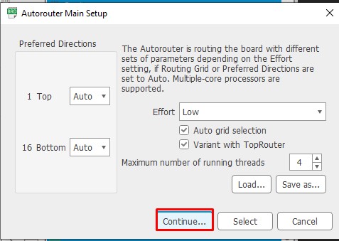
- in Auto router main setup click on continue.
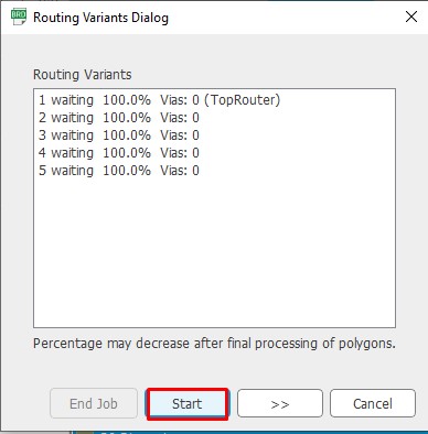
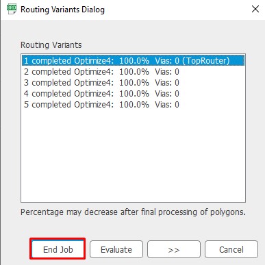
- in Routing Variants dialogs click on start, optimize completed. Note that the vias becomes zero and select top router (best auto routed path for given ckt)
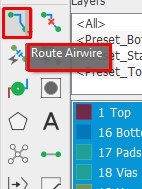
- For hand routing arrange all the components on the layout.
- Click on rout airwire.
- Arrange all the route one by one such that no two connecting wires cross each other.
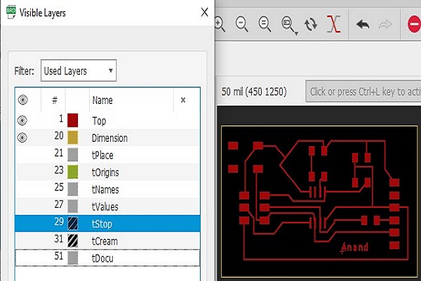
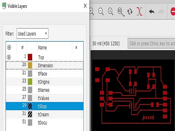
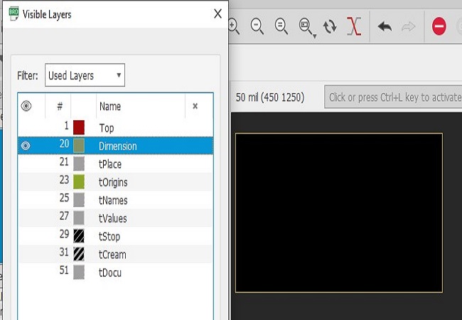
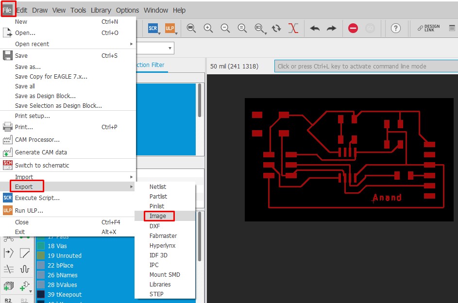
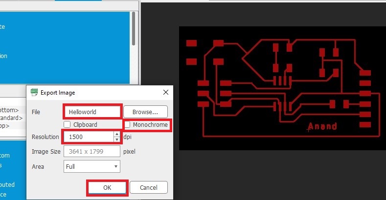
Step10 .Export the PCB layout
- Remove all the unwanted layers and prepared the PCB image for export.
- Goto file menu click on export select image
- Set the name ,location and resolution of the image.Also tick on monochrome for converting the board image into the trace.
Board Images
Reference image
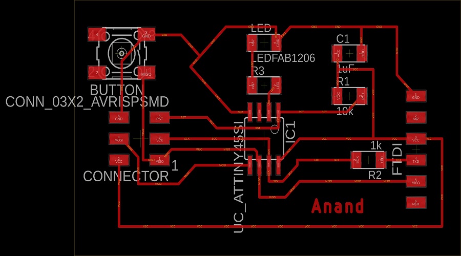
Autorouted
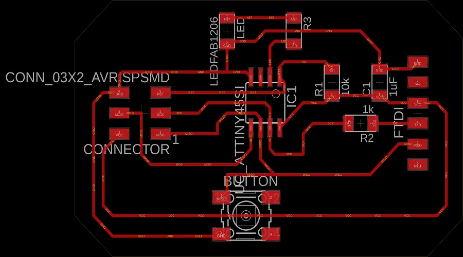
Handrouted
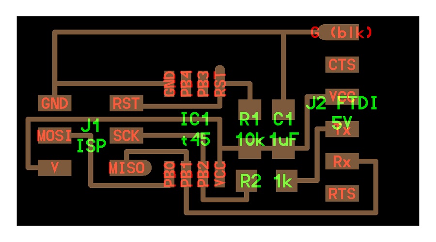
Traces images
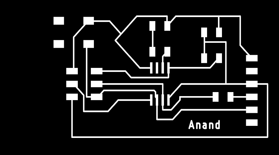
Autorouted
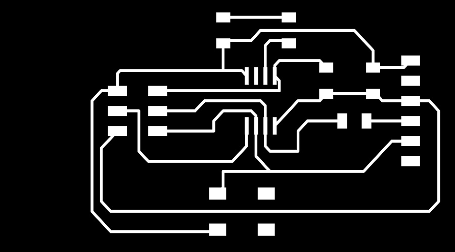
Handrouted
PCB milling by SRM 20
- Open the Fab module
- Select the .png image.I have selected the autorouted hallo world board.select the mill traces(1/64’’).select calculate
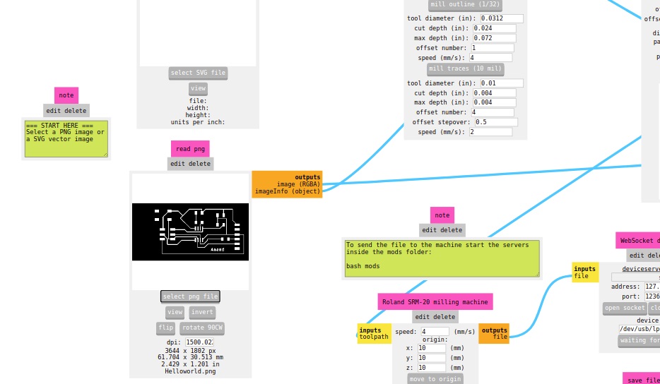
- Set the origin. Click on open socket. Click on send file. Milling started.
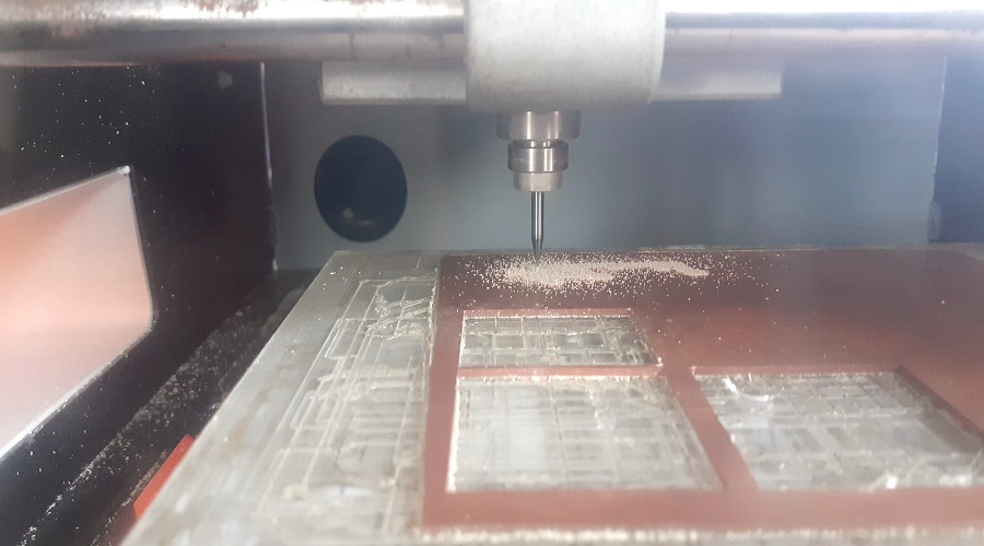
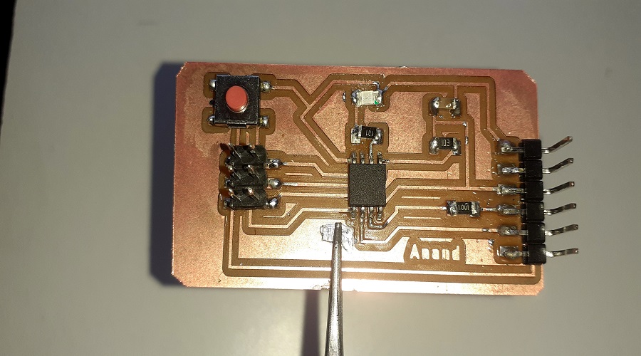
Milling PCB
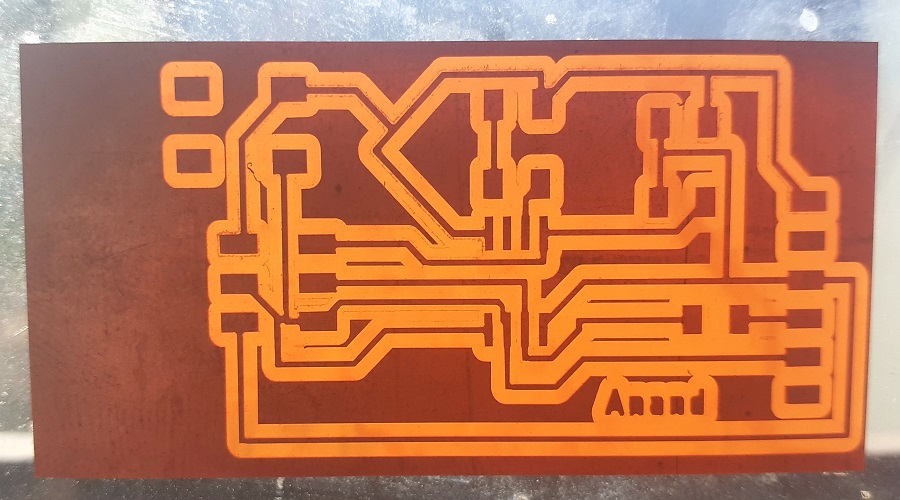
Milled PCB trace
Soldering PCB.
- After completing the milling the PCB mount all the components on the PCB.follow all the soldering rules as mention in the Electronic production week.
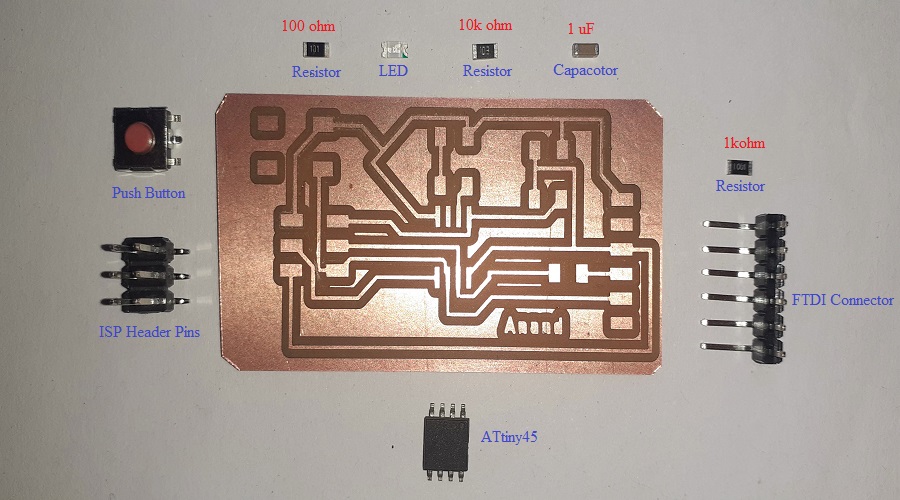
Stuffing PCB Components
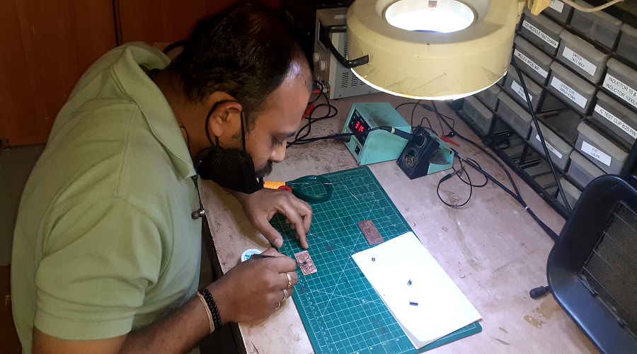
Soldering Components
Solder PCB
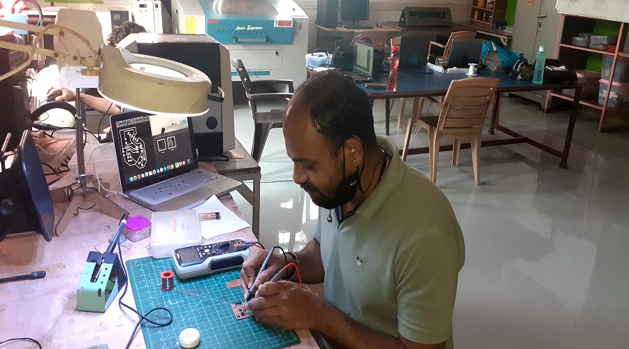
Continuity Checked
Programming the PCB.
For the programming the helloworld PCB we are need of FAB ISP already design in Electronic production week. Download the Arduino IDE software for editing the program.
- Install Arduino IDE software
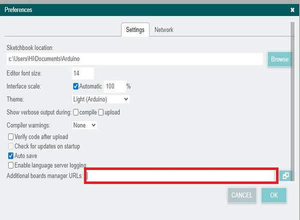
- Go to the file select the preference, goto the additional manager url.
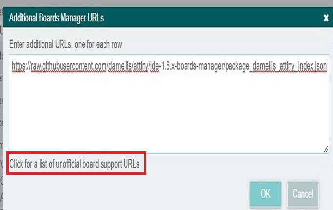
- click on list of unofficial board support urls.search Attiny 45.add url in the manager window click ok.
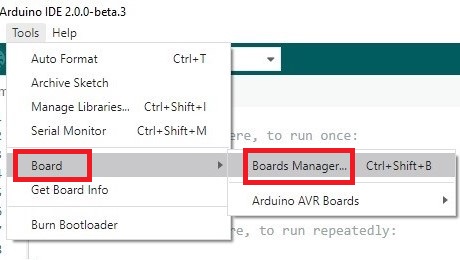
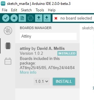
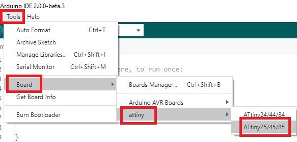
- Go to tool => Board => Board manager =>Install ATtiny .
- It appears in Board =>select Attiny =>Select Attiny45
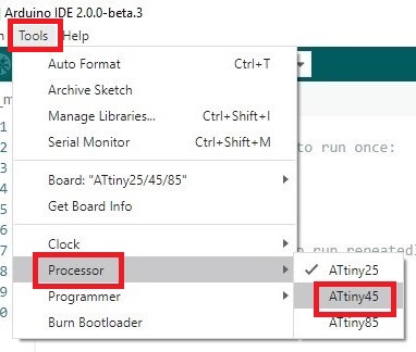
- Go to tool => Processor => right check ATtiny 45.
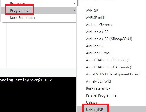
- Go to tool => Programmer => select USBtinyISP
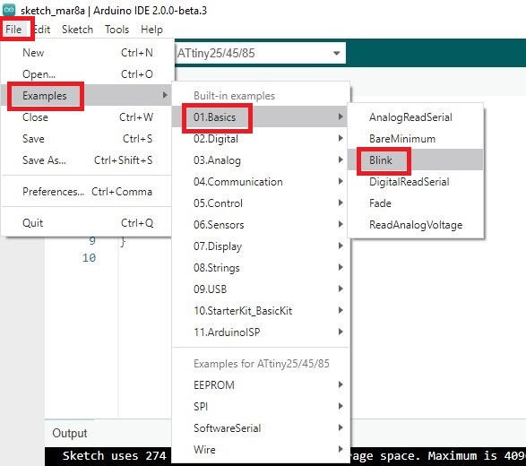
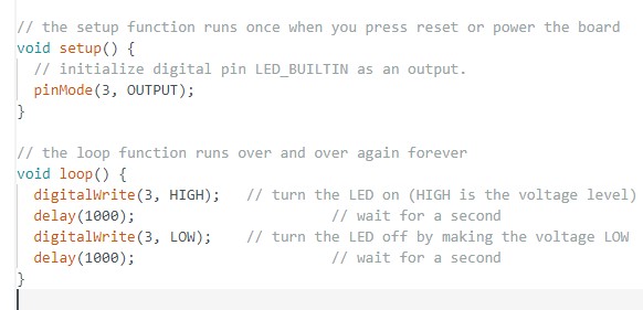
- Goto skech=>File menu=>Examples=>Basics=>Blink.
- Edit the blink program according to pins. Upload in to ATtiny45.Run the program.
- Blinking code of LED.
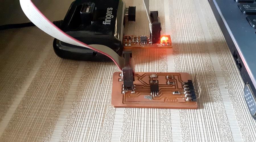
Connected PCB with FAB ISP
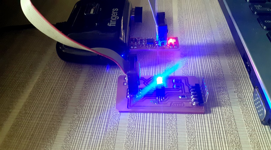
LED Glow in PCB
Video shows the Blinking of LED on board.
Learning outcomes
- Tested different parameters like current, voltage,...etc of PCB by using different devices like multimeter, oscilloscope,...etc to get and introduction of how we can use these devices to measure different paramters as per our requirment .
- Used Eagle software to redesign Helloworld circuit board.
- In Eagle design the board by Autorouter as well as hand router.
- In Autorouter rout is created by software where as by hand routing you can design circuit in own way.
- It was difficult for me to design a new circuit. This week was helped me a lot to know the small but very important parameters like Vcc, GND(ground), MOSI, MISO,...etc . Which are necessory to consider while desiging a new circuit.
Problem faces
- Net label properly in schematic other wise the components are not connected properly.
- Set the DRC parameters before hand routing.
Downloads
- Hello world Schematic Eagle file
- Hello world Board Eagle file
- Hello world Board Trace png image
- Hello world Board cut png image
- Arduino Code for Led Blink.
SAMS-Smart Azolla Multiplier System by Anand S. Tale is licensed under CC BY-SA 4.0![]()
![]()
![]()