Fourth week assignment is Electronics production. In this week we have to characterize the design rules for the PCB production using SRM 20 Milling machine and program it.
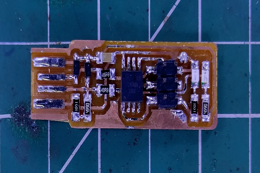
Hero shot.
Assignment-4
Electronics Production
OBJECTIVES
Group assignment
- Characterize the design rules for your PCB production process: document feeds, speeds, plunge rate, depth of cut (traces and outline) and tooling.
- Document your work (individually or in group)
Individual assignments
- Make an in-circuit programmer by milling and stuffing the PCB, test it, then optionally try other PCB fabrication process.
Learning outcomes
- Described the process of milling, stuffing, de-bugging and programming.
- Demonstrate correct workflows and identify areas for improvement if required
About Group Assignment
In the group assignment we find the width of traces that can mill on SRM-20 milling machine in our lab. For more description about trace width please click on the above link of group assignment. In which the design rules for PCB production/milling process is explained. The PNG image of traces and cut are shown below image.


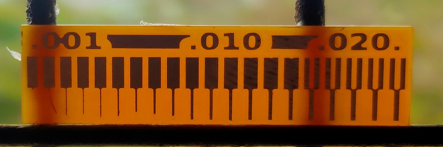
Experimental trace
Summary
With this experiment we find out that if the distance between the the traces is less than 0.0156" (diameter of end mill 1/64"),the milling machine will not mill it,also Your pcb design trace width should not less than 10 mil and gap between traces should be more than end mill diameter 0.0156".
Individual assignment on Electronics Production
In this week we deal with Electronics production. we have to milled the given design of Fab ISP(PCB) stuffed it with given components and program it with following steps.
- About SRM 20
- Download the circuit image.
- Roll of Mods Software
- Operating SRM 20 Milling Machine
- Stuffing the PCB
- Programming through Software
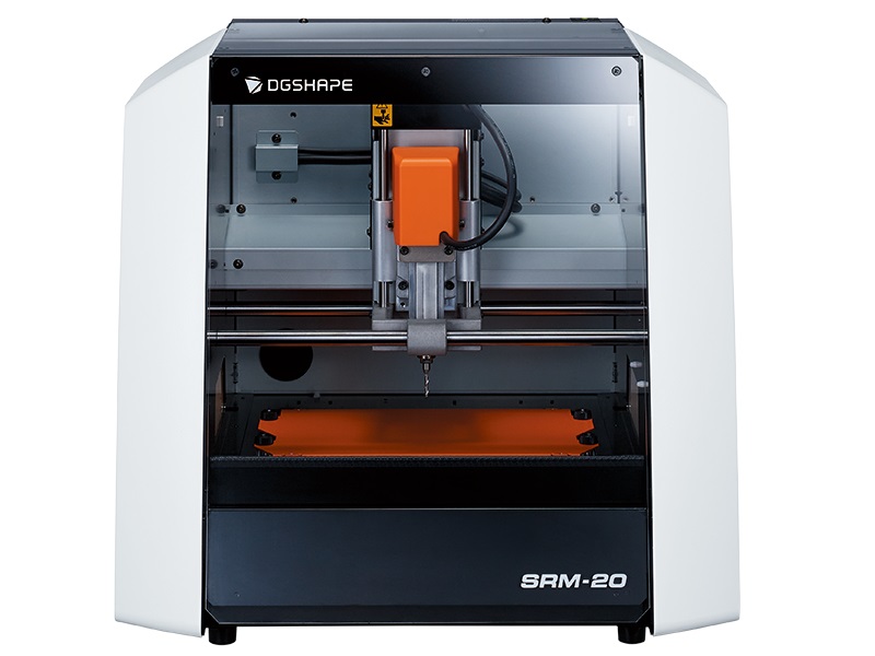
About SRM 20
In Vigyan Ashram we have monoFab SRM-20. It is machine on which we can mill a PCB (Printed circuit board). This machine have a fully-enclosed cabinet. It reduces the spread of dust and noise in the surrounding. The cabinet of SRM-20 is made of glass, due to which we can see the progress of milling. It has an intelligent safety interlocking door which can automatically pauses the machine when it is open. This feature will avoid possibility of any human harm or accident. But this machine does not have the provision of light in it. If we have to mill the pcb at night we can not see the progress clearly due to absence of light. Because of which many time we can not see the errors in our board and the damage of end mill.
Specifications
What is PCB?
A printed circuit board (PCB) mechanically supports and electrically connects electrical or electronic components using conductive tracks, pads and other features etched from one or more sheet layers of copper laminated onto and/or between sheet layers of a non-conductive substrate.(Wikipedia)
What is ISP?
The FabISP is an in-system programmer for AVR microcontrollers, designed for production within a FabLab. That is, it allows you to program the microcontrollers on other boards you make, using nothing but a USB cable and 6-pin IDC to 6-pin IDC cable.
Download the circuit image
Download available circuit design from "Electronics Production Week" page from the schedule of "Fab academy 2021".
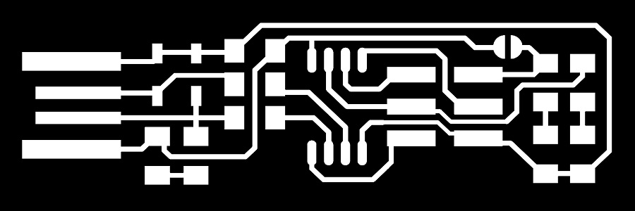
Brian FAB ISP Trace for milling

Brian FAB ISP Trace for outline
Roll of Mods Software
MODS community edition is a fork of CBA mods research project. mods is a modular cross platform tool for fablabs. It is based on independent but interrelated modules. mods could potentially be used for CAD, CAM, machine control, automation, building UI, read input devices, react to to physical models, and much more. The possibilies are endless.
MODS Origin is a cloud-based interactive, integrated, and intuitive tool developed along side a leading EPC to make sure they have the right tool for the right job. (Internet source)
It is acts as a interface between our operating system and machine(SRM-20). We can also use mods for making a program for any machine as per our requirement. If we want any additional feature in our machine then we can build a program for our machine in MODS.
For milling FABISP i am going to used SRM-20 PCB milling machine. This machine required traces,hole drill and outline rml file. To generate the traces and outline file go through the following procedure
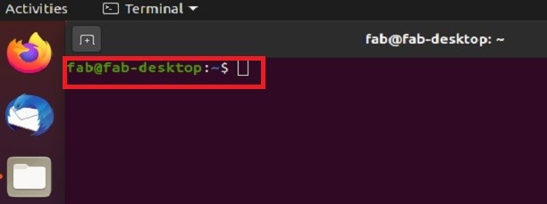
- Boot the Desktop terminal using Ubuntu OS.
- Open Terminal and use commands
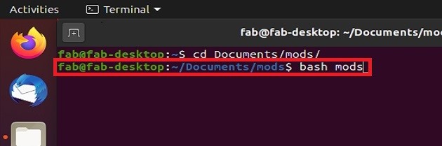
- cd Documents to change directory.=> mods => bash mods
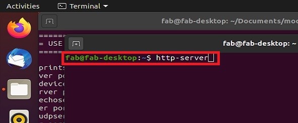
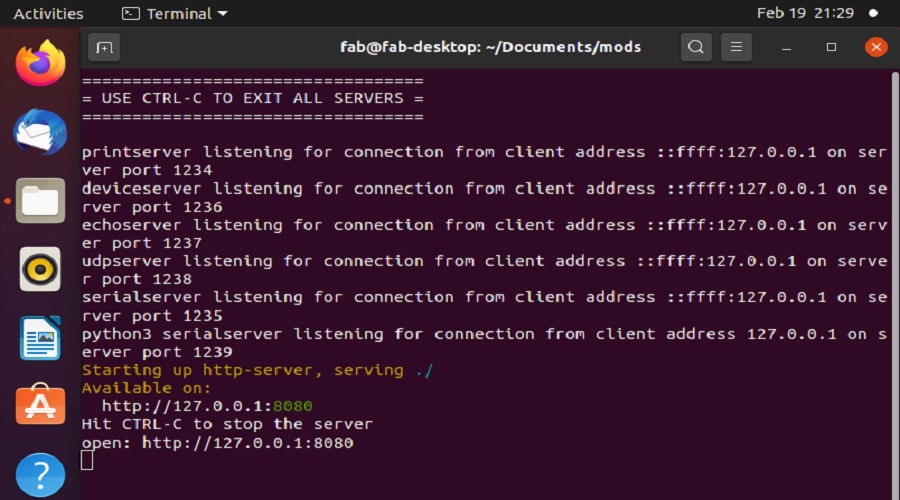
- Again Open New Terminal and use commands
- Cd Documents => http – server
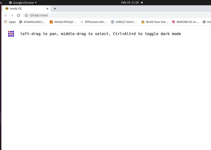
- This will open a Window in Google Browser.
- Right Click in the Window
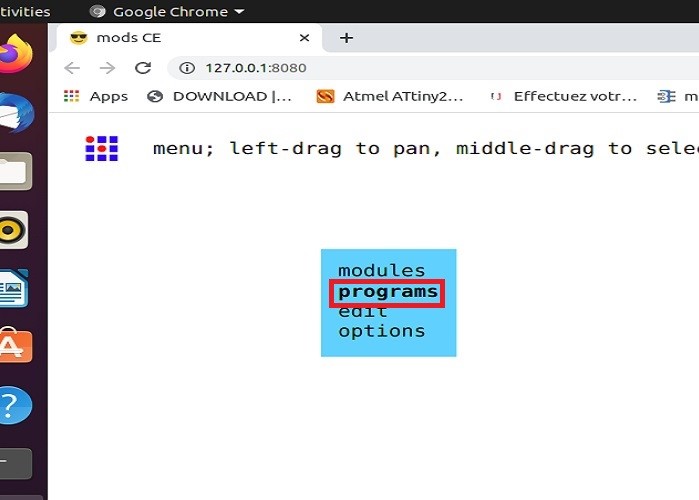
- Four options will be displayed like Modules, Programs, Edit, Options etc.
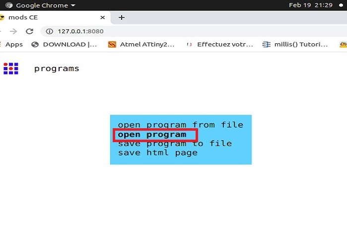
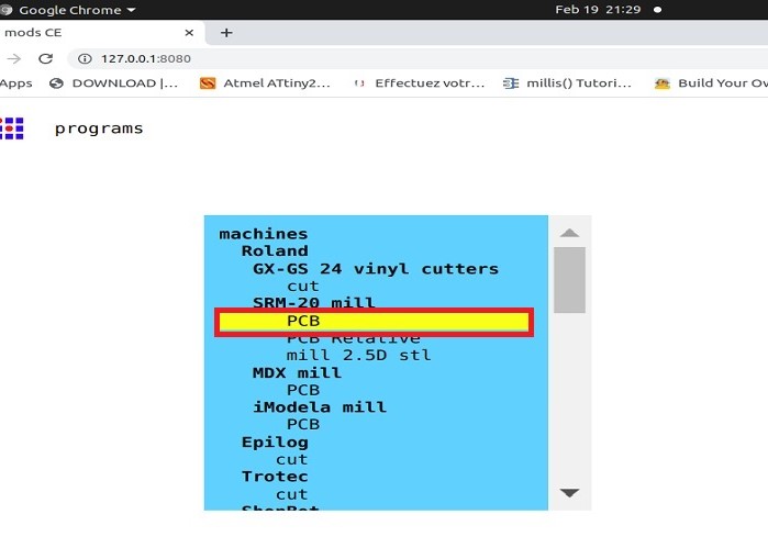
- Select Program=>Select SRM20 mill=>PCB
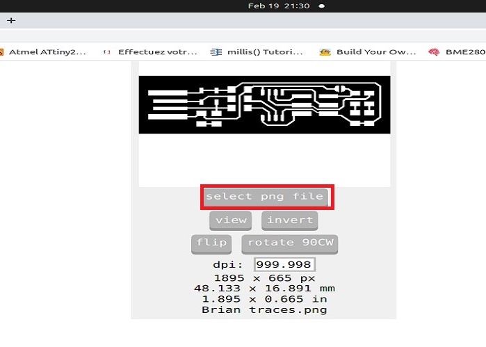
- Select the Image,Check the format of the image (.png)
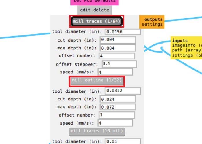
- Select the mill trace 1/64” for PCB traces.
- Select the mill outline 1/32” for PCB outline.
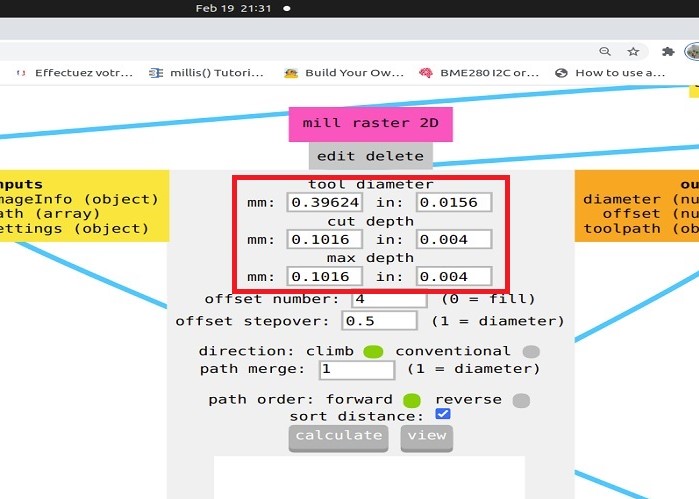
- Once we select the end mill all the parameters get set with its standard value.if any one want to repassed then he or she will changed the parameters.
- Tool Diameter: It repsent the diamenter of end mill.
- Cut Depth : Amount of depth that will be cut per pass.
- Maximum depth : Amount of depth that will be cut in total
- Offset number: Number of out lines.
- Offset step over : Stepover is how far from the previous cut the next cut occurs. A cut it made, the bit is "stepped over", and the next cut is made.
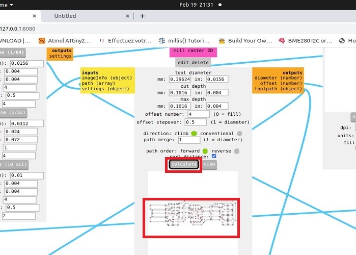
- Select the calculating option.we can see the path of our module program the way through png image converted into rml the language under stood by SRM 20 machine.
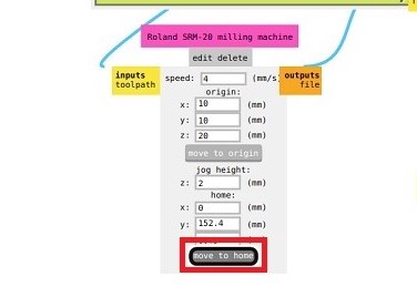
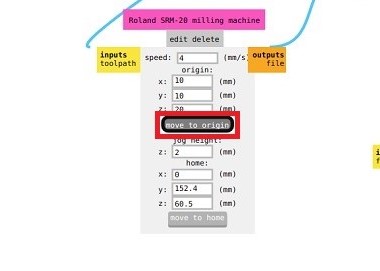
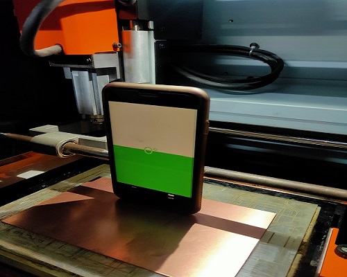
- Click on the open socket.set the speed of of milling machine.Set the origin at home position, then set according to X, Y, Z axis position.
- Note that machine head moving along X axis, Bed moving along Y axis and end mill along z axis.
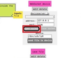
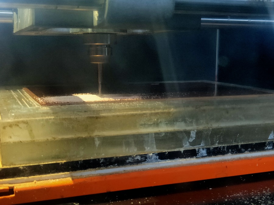
- Again click on calculate , it will trace again. Click on open socket and finally click on send file to device.
- The SRM 20 machine will accepetc the command and start milling.
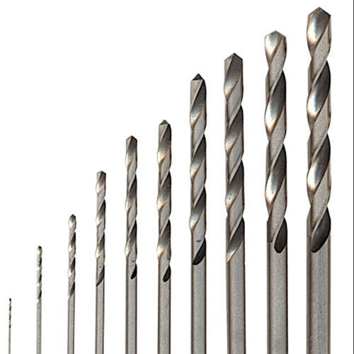
End mill Vs Drill bit
- the carbide end mill is the most widely used milling cutter tools on CNC machines.
- They can be cut simultaneously or separately, mainly used for plane milling, groove milling, step face milling and profiling milling.
- The common milling cutter diameter is 1~25, less than 1mm, and it is often called the micro-diameter.
About End mill

- It is a kind of equipment used in drilling engineering.
- it is mainly used for drilling, which is divided into through holes and blind holes (respectively referring to the original holes for reprocessing, and the original holes without holes to drill).
- The general processing size is 2~40mm.
About Drill bit
Operating SRM 20 Milling Machine
- Open the panel of machine and set the set the sacrificial layer on the bed.
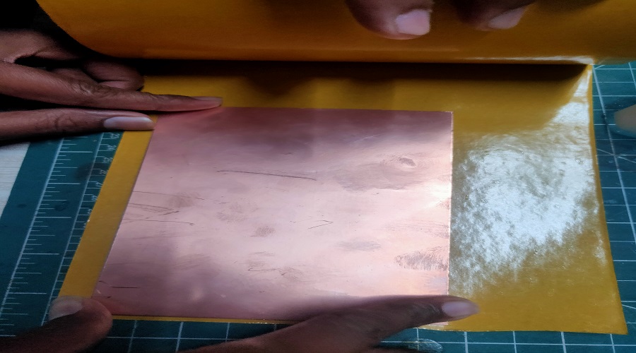
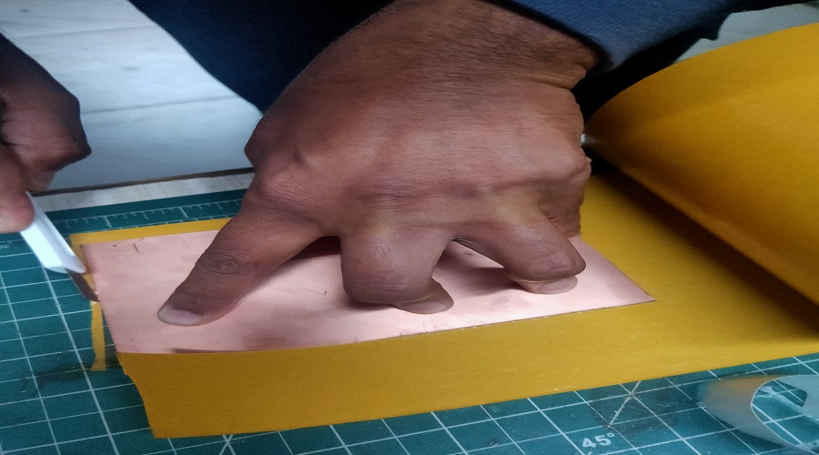
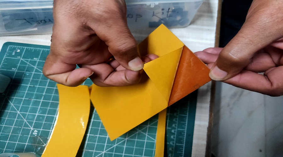
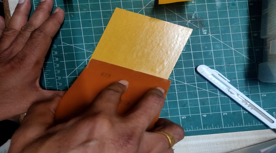
- Take pice of FR-1 type PCB material , clean it with acetone , stick two way tape on lower surface .avoid the formation of air bubble.
- Now apply the blank PCB on the sacrificial layer with even leveling.
- Now closed the machine panel . Note that for milling operation machine panel must be closed.
- Start the machine, initially the head will set to the home position.
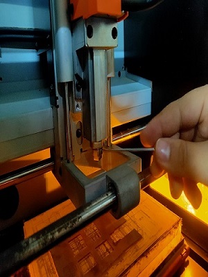
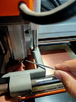
- Select the proper end mill as shown in images
- For milling operation used the 1/64” end mill. Open the chuck of the milling machine with allen key with anti clock wise rotation.
- Place the end mill care fully and tight it carefully and gently in clock wise direction.
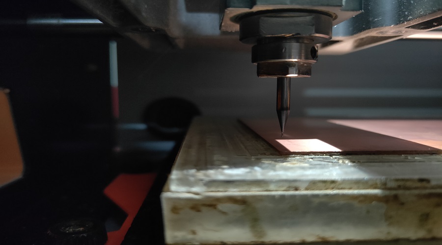
- Initially set the origin such that the Z axis i.e end mill is at slight above the PCB surface.
- Now open the chuck so that the end mill touch the PCB surface,now tight the chuck screw gently,note the Z axis value. This is called gravity setting.
- Now finally set the origin for milling process.
- Same process is repeated for cutting only by replacing 1/32” end mill and select cutting.png image.
- Now PCB is ready for stuffing.
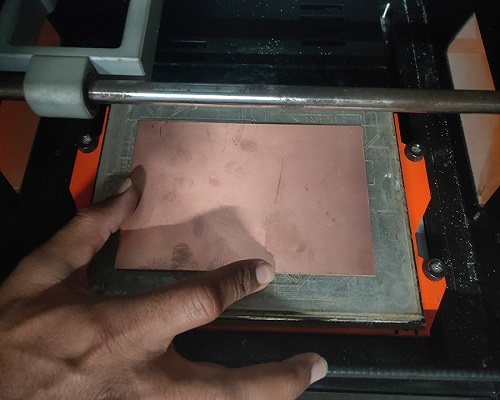
Appling Blank PCB
Even Leveling
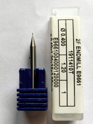
1/64" end mill for milling trace
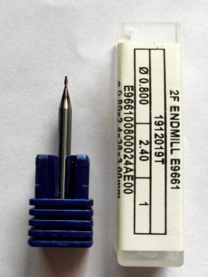
1/32" end mill for cutting trace
Opening of chuck
Applying end mill.
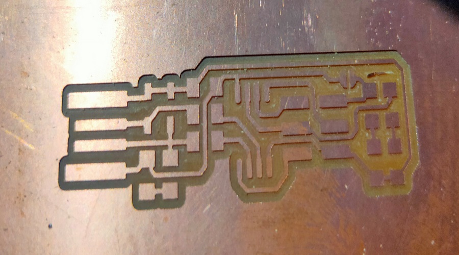
Milled trace
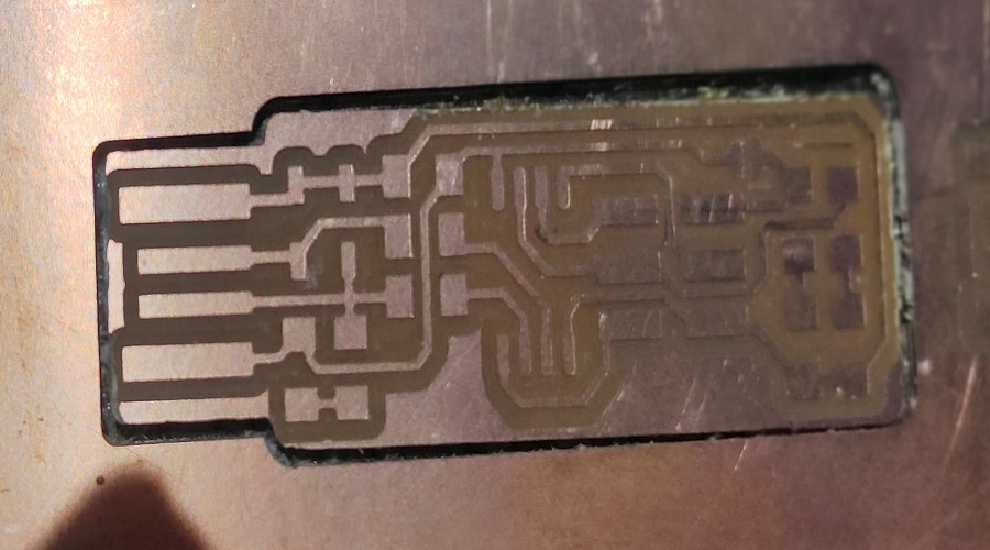
Cutout milled trace
Stuffing the PCB
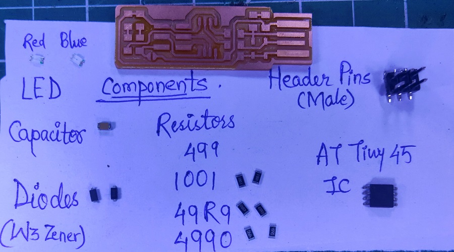
After the milling processed the PCB is ready for soldering, Different components are mounted on the PCB.
- 1x ATtiny45 or ATtiny85
- 2x 1kΩ resistors
- 2x 499Ω resistors
- 2x 49Ω resistors
- 2x 3.3v zener diodes
- 1x red LED
- 1x green LED
- 1x 100nF capacitor
- 1x 2x3 pin header
The list of components .
Sorted the above listed components.
Few things related with soldering
- Used Twizzer When soldering the any SMD components on PCB .It helps to pick or hold the component and to solder in it correct position.
- Used flux on the PCB it is useful to make a strong bonding of electronics component on the copper. I have used tin lead material for soldering.
- For soldering stuff the entire component on PCB board and place the entire component properly on the edges of PCB.
- Connect all the component precisely makes sure that there is not made any short-circuit
Problem I have faced
- It is difficult find the anode and cathode of SMD Zener diode.there is line mark on cathode,check it carefully.
- Note that normal diode is connected in forward bias and Zener diode is connected in reverse bias.
- Check resistror value correctly,used google.
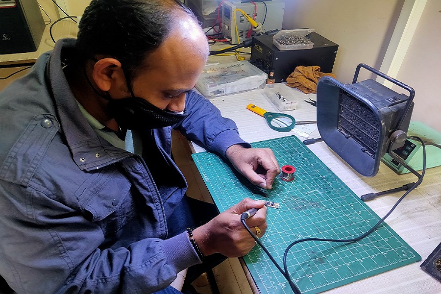
Soldering components on PCB
Soldered BCP
Programming PCB through Software
After successfully completing the soldering process you have to program our ISP board through Linux or Windows operating system.Fab Academy provides an instruction for software installation in PCB. All the instructions are vary as per operating system.In our FABLAB Linux operating system has already installed on one pc.
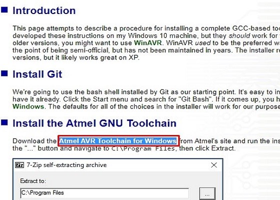
Though I used windows 10 operating system,have gone through" Atmel AVR Toolchain for Windows".
For windows the process was slightly crirical.
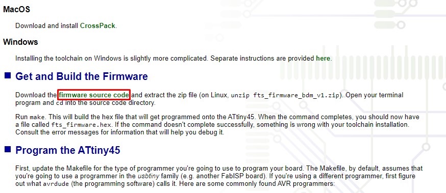
Goto the Fab Academy 2021 Schedule=>Assienment"Electronics Production"=>individual Assignment"in-circut programmer"=>in system developement"Brian"=>go to Windows instillation process click on "Here"=>Goto Install the Atmel GNU Toolchain and download "Atmel AVR Toolchain for Windows"
Steps follows on Windows Operating System
- Firstly its need to install Git, we have alredy Git Bash. so click on start menu, search "Git Bash" it will get open.
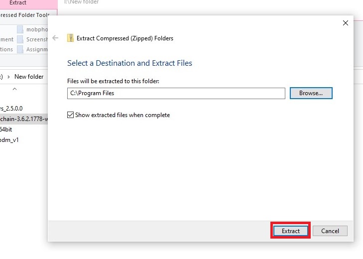
- Download the Atmel AVR Toolchain for Windows from Atmel's site and run the installer. When asked where to extract the files, click the button and navigate to C:\Program Files, then click Extract.
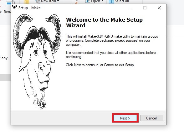
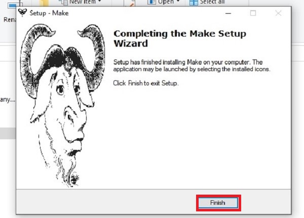
- Download Gnu Make and launch the installer.
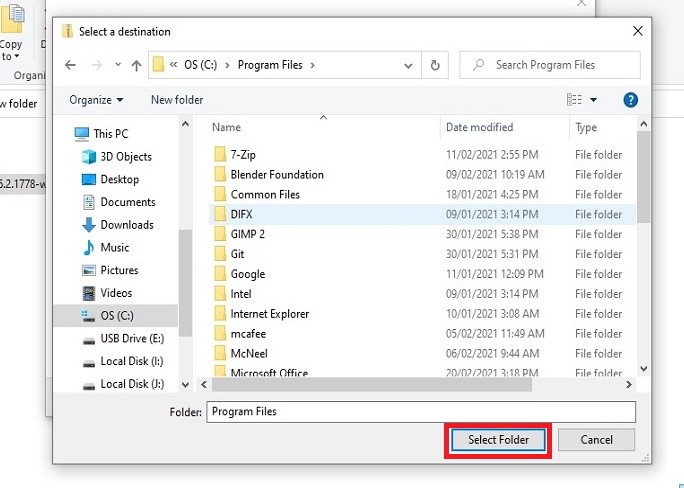
- Download avrdude. Unzip the archive, and copy the archive inside to C:\ProgramFiles.
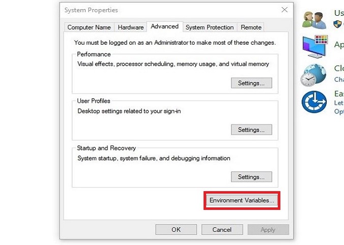
- Then go to the Start menu and search "Advanced System Settings". Under the Advanced tab, click the "Environment Variables" button.
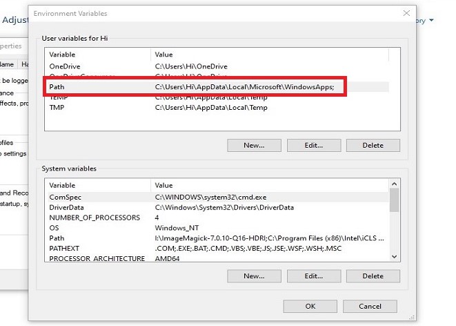
- Under User variables, select "Path" and click the Edit button. If you don't already have a variable called "Path", click the New button to create it, enter "Path" without the name, and fill out the value as described below.
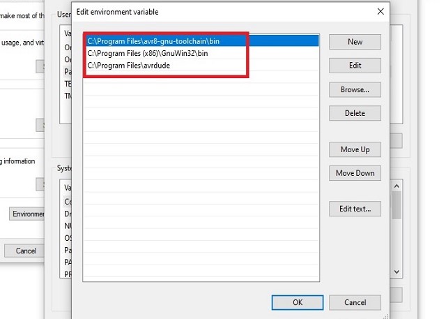
The three values to add are:
C:\Program Files\avr8-gnu-toolchain\bin
C:\Program Files (x86)\GnuWin32\bin
C:\Program Files\avrdude - Now all software were installed.
- Download the firmware source code and extract the zip file on desktop. Open your terminal program and cd into the source code directory.
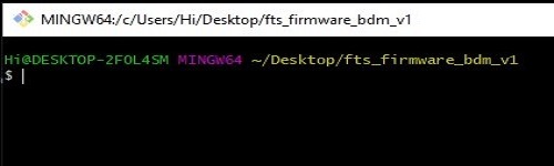
- let’s check whether all are working or not?open the "Git Bash" from Start Menu>apply the command> cd Documents/fts_firmware_bdm_v1then press enter.
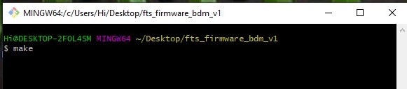
- run "make"command and press enter>this command is OK.This will build the hex file that will get programmed onto the ATtiny45.
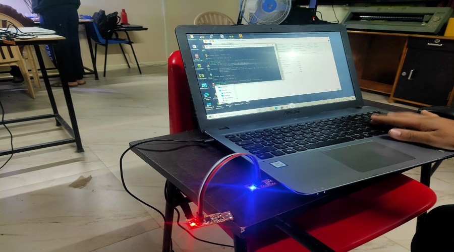
- Now comnect the Fab ISP to the laptop with the another programmer through the connectorsThe LED will glow in both the ISP
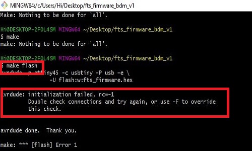
- Now type “make flash” press enter>this command show the error as shown in the image
- This means that avrdude successfully found your programmer, but failed to talk to a target board because some of the compnents were not connected properly
- So recheck all the connections. In my fab ISP one pin of ATtiny45 was not connected properly. Connected it again checked the ISP.
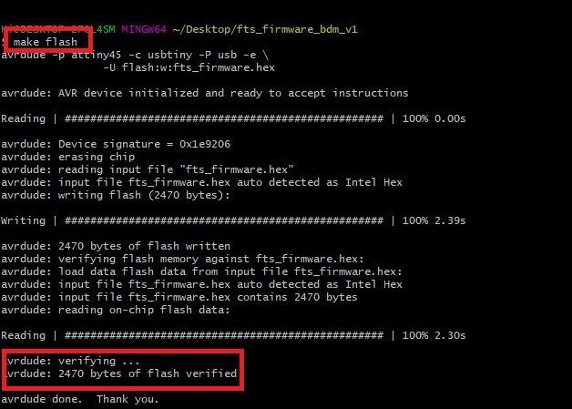
- Now again run “make flash” press enter> this command were run shows the message.This will erase the target chip, and program its flash memory with the contents of the .hex file you built before. You should see several progress bars while avrdude erases, programs, and verifies the chip.Once you run the command the LED start blinked as shown in image.
- Video when "make flash" command were run
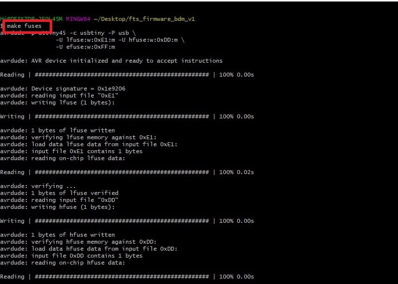
- Run “make fuses” command. This will set up all of the fuses except the one that disables the reset pin.Again, you should see several progress bars from avrdude.
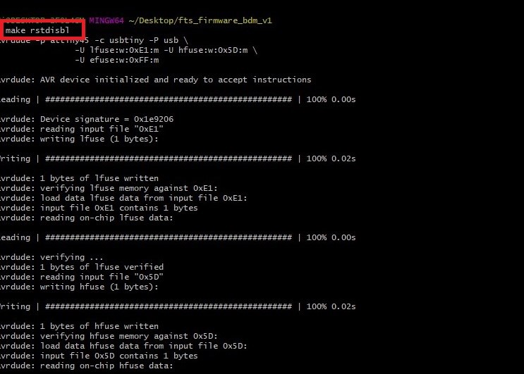
- Run “make rstdisbl” command. This does the same thing as the make fuses command, but this time it's going to include that reset disable bit as well. You should see some progress bars, and with that, avrdude will never be able to talk to this chip again through the ISP header.
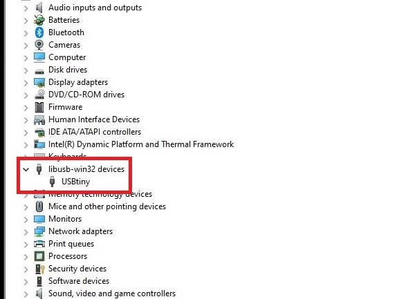
- Now finally check the device manager ,the Fab ISP was recognized and here it was.
Learning out comes
- In this week I have studied various characteristics of SRM-20.
- How to operate SRM-20 by giving commands using Mods Software
- How to stuffed and solder SMD electronic components on raw PCB board.
- How to program FABISP by using Windows operating system through Git Bash.
Downloads
SAMS-Smart Azolla Multiplier System by Anand S. Tale is licensed under CC BY-SA 4.0![]()
![]()
![]()