Third week assignmet is Computer controlled cutting.In this assignmentlearnt lot of things related to laser cutting.The things I taught in my class about laser, actually find its applications.I also use vinyal cutter for loge making.
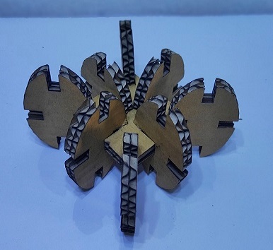
Hero shot
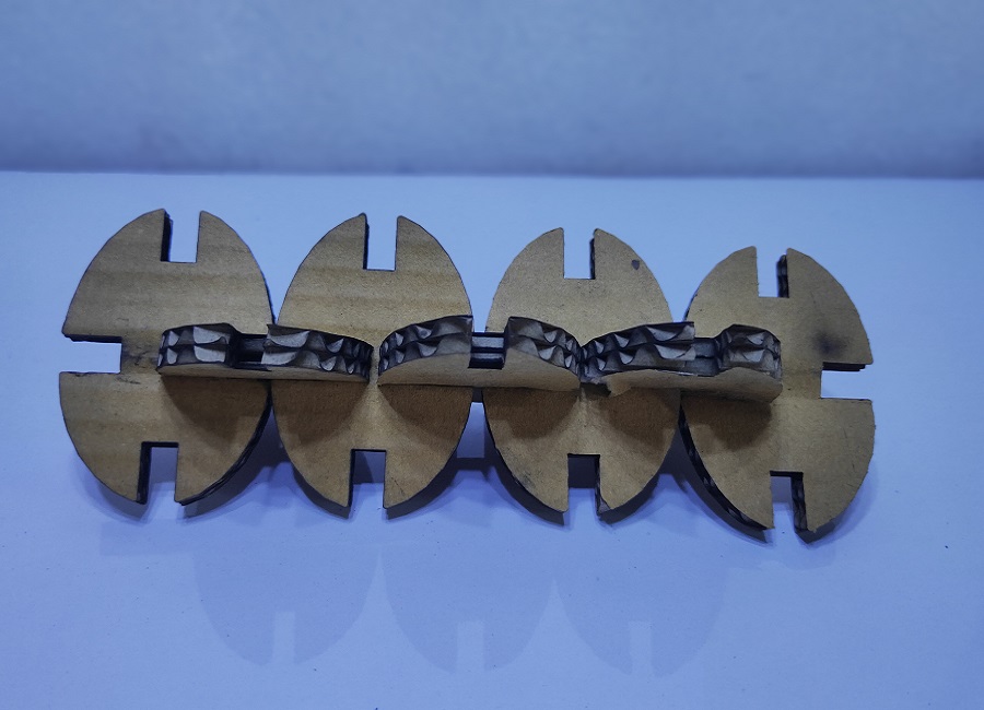
Hero shot
Assignment-3
COMPUTER CONTROLLED CUTTING
OBJECTIVES
Group assignment
Individual assignments
Learning outcomes
About Group Assignment
After the yesterday, Neils lecture on Computer controlled cutting , today our instructor details us about Laser cutter.Though its group assignment we divided our work for completed it smoothly. For the Group assignment, we had to Characterize your laser cutter’s focus, power, speed, rate, kerf, and joint clearance document our work (individually or in group).
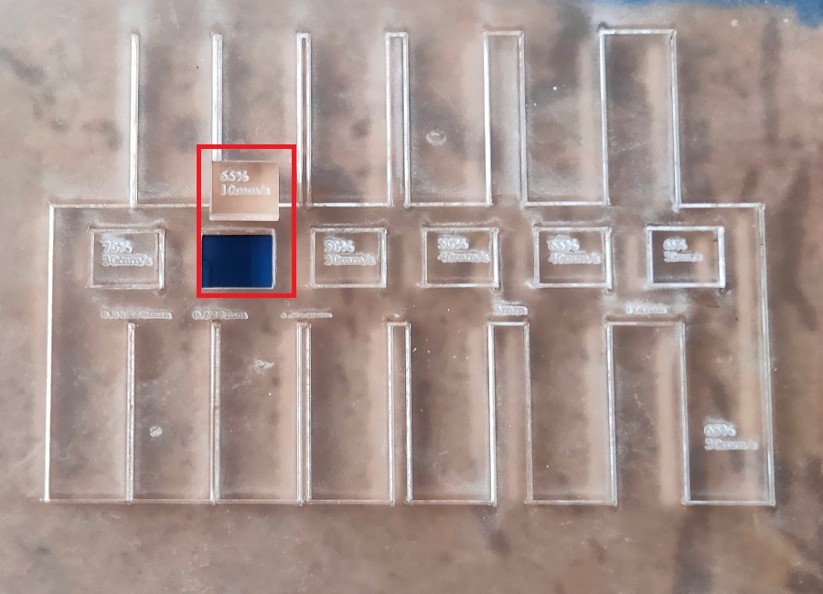
We have designed a Comb like design having 6 squares with variation in Speed and Power to calculate the kerf of the machine on various materials. We have divided the materials amongst us. The material used by us for the kerf calculation were Cardboard (6.91 mm thick), MDF – Medium Density Fiber (3.81 mm thick), Foam (4.49 mm thick), Plywood (5.25 mm thick) and Acrylic (3.75 mm thick). I have taken the reading for the MDF material. These reading were then documented in a Google Sheet circulated earlier. The consolidated results were then collectively presented in the Group assignment.
Summary:
After completing the experiment we found that 10mm/s is the prior speed and 65% is power for cutting Acrylic material with thickness 3.75mm.
Individual assignment on Laser Cutting
ABOUT LASER
Laser stand for Light amplification by stimulated emission of radiation.when atoms of active system of laser medium absorbed energy goes to the excited energy state , after completation of life time it jumped from higher energy level to the ground energy level.during this transition it emit photons by the process of stimulation emission.these photons get applied in resonator,emits Laser light which is highly coherent, monochromatic, intense and unidirection.
In VA we are having CO2 laser which one the powerful laser among all the laser emit laser light in IR region(10.6µ).
ABOUT LASER MACHINE
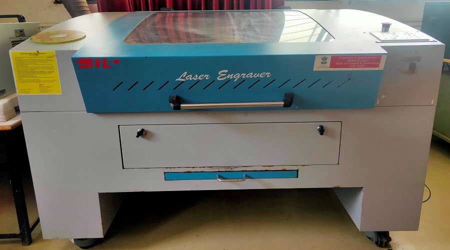
Name : SIL Laser Engraving - Cutting Machine
Application: SIL Laser Engraving - Cutting Machine is versatile & finds application in signage, indoor & outdoor advertisement, art & craft, gift, shoes, toys, garments, model cutting, papers & packaging, wood & MDF cutting industry, interior, decorators and many more.
SPECIFICATION
Model NO. |
1325-1318 |
|---|---|
Engraving speed |
0-640000mm/min |
Cutting speed. |
0-30000mm/min |
Laser type |
Co2 DC glass laser tube |
Laser power |
80 Watt |
Positioning Accuracy |
80 Watt |
Processing area |
900 by 600mm |
Working speed |
Adjustable |
Power supply |
AC 220V+ 5%; 50/60Hz |
Format supported |
AI, BMP, PLT, .DXF, DST etc. |
FEATURES
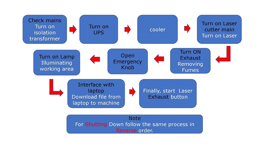
Process to start Laser Machine
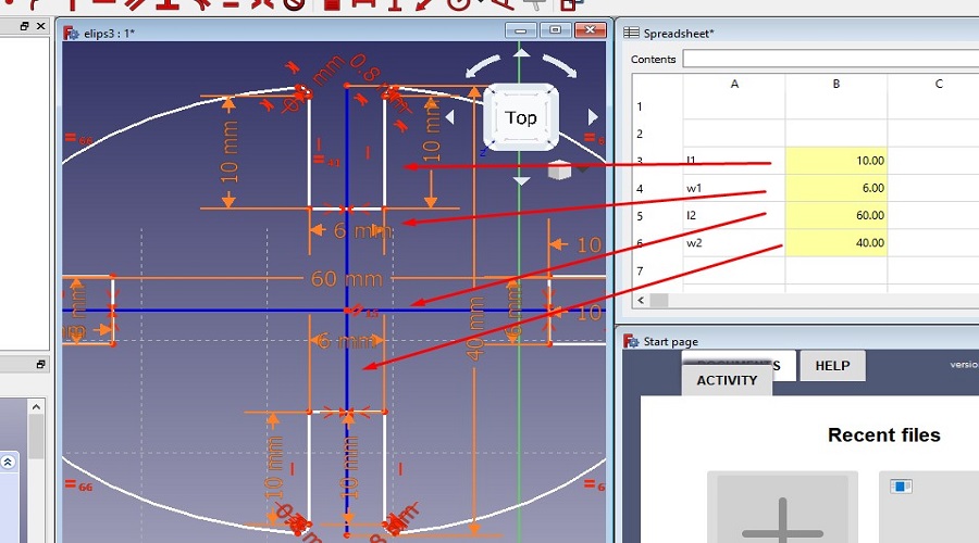
Parametric design in freecad using Spreadsheet
Parametric design is a process based on algorithmic thinking that enables the expression of parameters and rules that, together, define, encode and clarify the relationship between design intent and design response. Simply if we change any one parameter of design all the parameter are changes with relation of given one.(Wikipedia)
For the parametric design consider the following steps
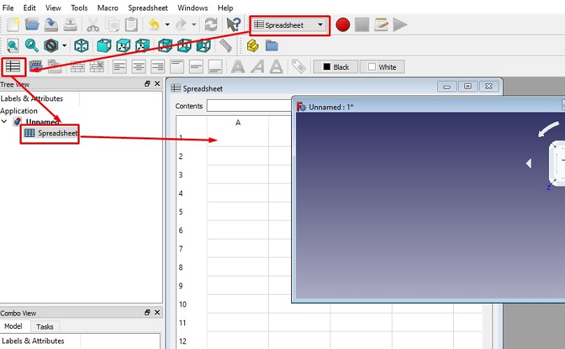
Step 1. create new parametric spreadsheet
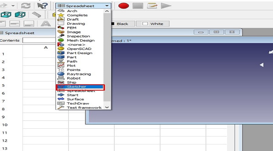
Step2.Create sketcher with spreadsheet
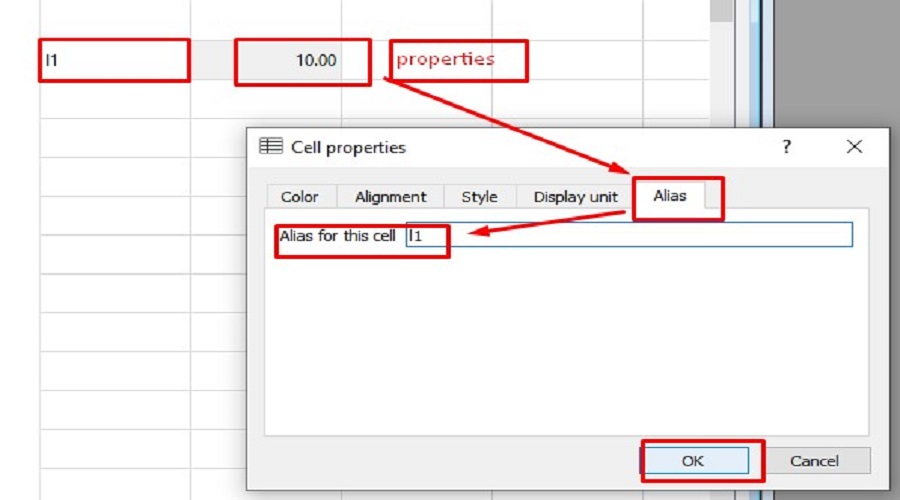
Step3.Adding parameters in the Spreadshee
Step4.Drawing shape in Sketcher and adding constraints
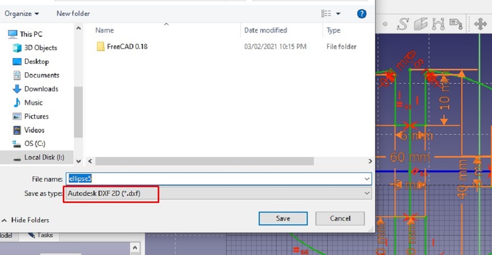
Step 5. Draft workbench
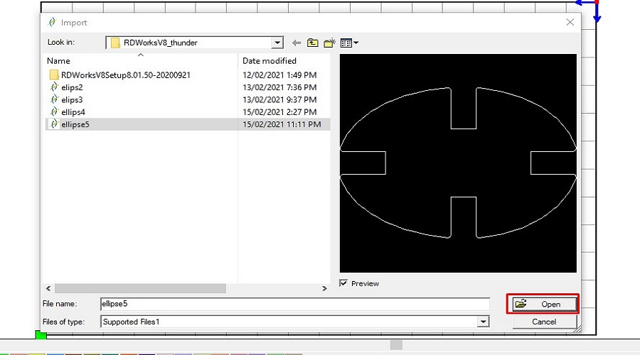
Step6. use RD works Software
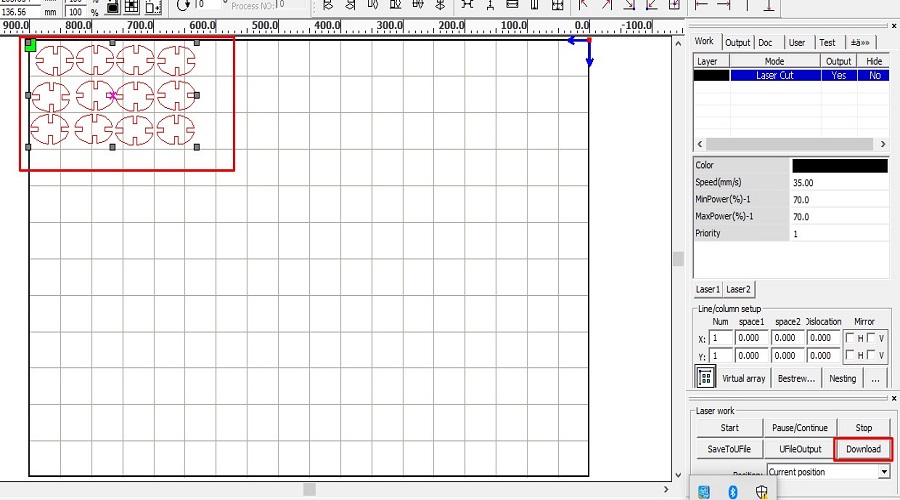
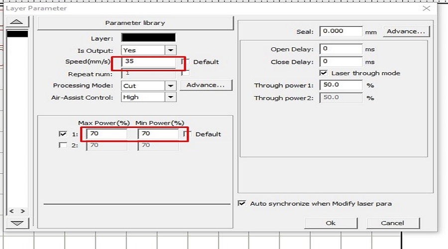
Step7.Set the layer parameters(Speed & power)
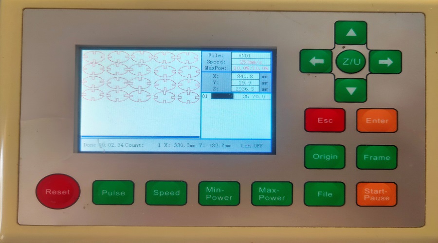
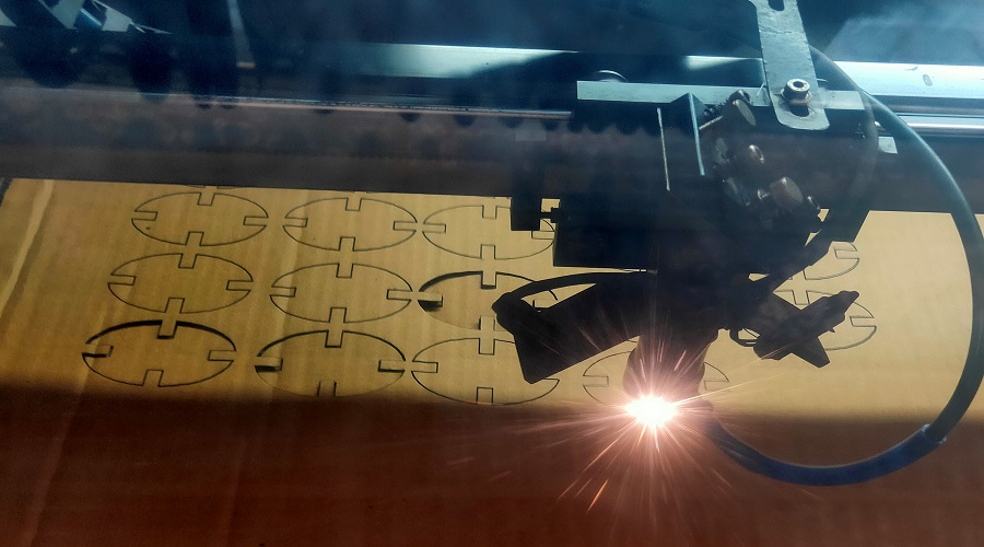
Step 8.Hands on Laser cutter
Step 9.Different Press fit assembly.
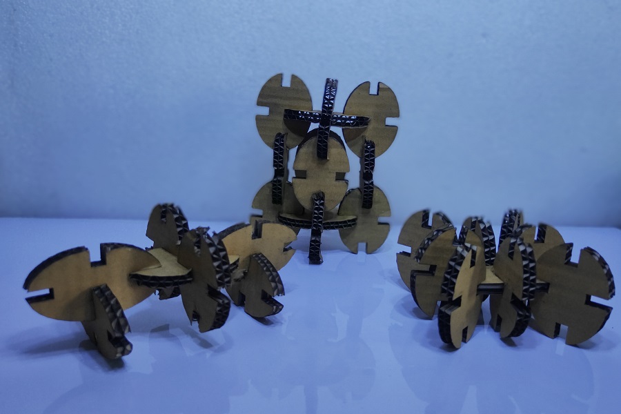
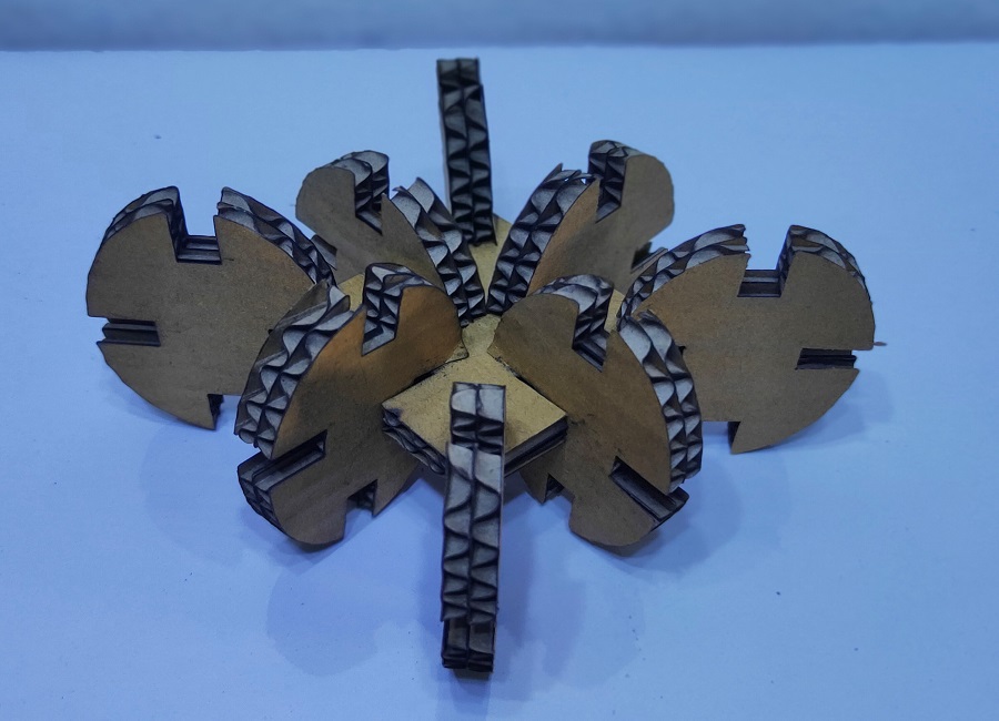
Hero Shot.
About Vinyl Cutter
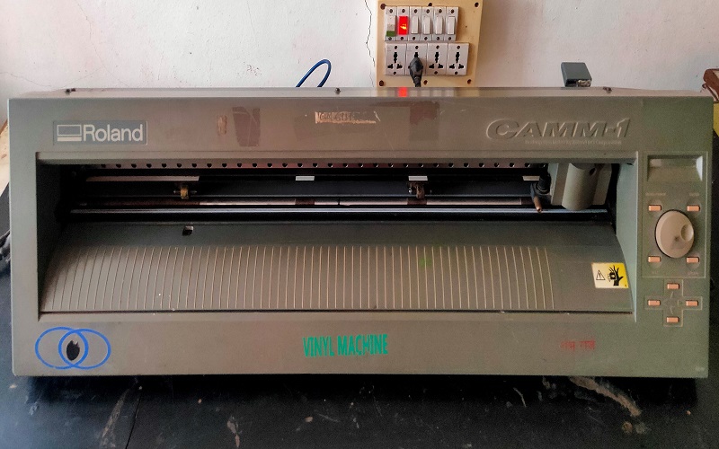
A vinyl cutter is a type of computer-controlled machine. like a printer controls a nozzle, the computer controls the movement of a sharp blade over the surface of the material. This blade is used to cut out shapes and letters from sheets of thin self-adhesive plastic (vinyl). Our FabLab-0 at Vigyan Ashram, Pabal has Roland Camm-1000. It is used for cutting the vinyl, even plastic film, copper film for electronics PCB design. We had to cut the logo or any design on this machine. This machine tempts you to be creative and adds aesthetics to the product.
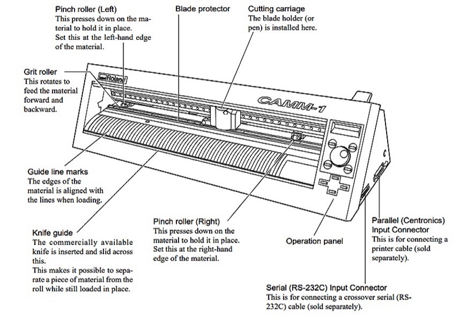
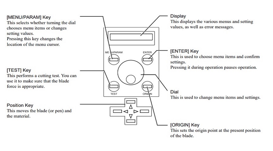
Different prats of Vinyl cutter
Control Panel of Vinyl cutter
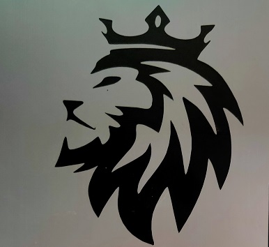
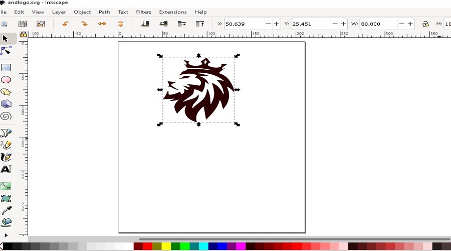
Creating Logo using Inkscape
In the previous assignment, I had already done a logo image using Inkscape bit map operation.I used the same for the vinyl cutting.
How to used Vinyl Cutter
Vinyl Cutting Order Flow:
Note:
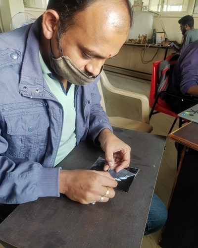
Weeding sticker carefully.
Removing and pasting logo sticker
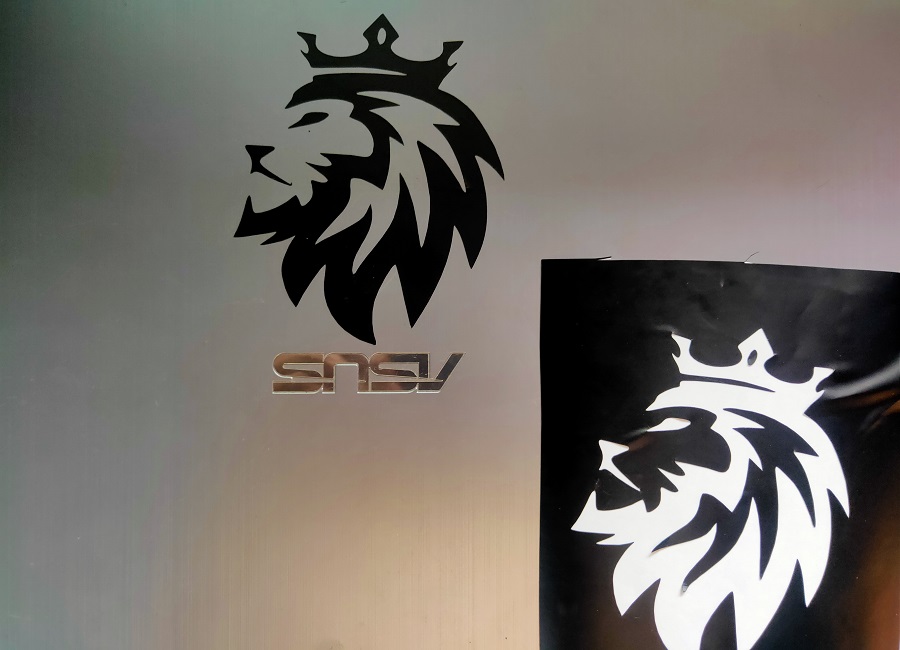
First logo Sticker made with Vinyl cutter
Learning out comes
Downloads
SAMS-Smart Azolla Multiplier System by Anand S. Tale is licensed under CC BY-SA 4.0![]()
![]()
![]()