Week fourteenth assignment is the Interface and Application Programming.In this week we are going understand the different graphical user interfaces and what is application programming. This week Neil has introduced as about various methods of making of application.On next day our lab manager gave brief lecture on what to do in this assignment.
Assignment-14
Interface and Application Programming.
OBJECTIVES
Group assignment
- Compare as many tool options as possible.
Individual assignments
- Write an application that interfaces a user with an input and/or output device that you made
Learning outcomes
- Interpret and implement design and programming protocols to create a Graphic User Interface (GUI).
About Group Assignment
Task for the group assignment is to Compare as many interfacing tool options as possible.
Individual assignment on Interface and Application Programming.
In this assignment we have task to write the application program that interfaces a user with an input &/or output devices that we made.I my filnal project I have used BH 1750 Light sensor as input device and Exahust fan as output device,so I have used both light sensor and exahust fan for this assignment.For this assignment I have used two Interfacing softwares,Processing and MIT App Inventor.For processing i used light sensor (Input device)and for MIT App Inventor I used Exhaust fan(Output device). the work flow of the assignment is given below.
- About Processing Sotware.
- Arduino code of BH1750 for Processing interface.
- Processing interface change the colour of rectangle.
- Processing interface Renders as simple tree.
- About MIT App Inventor
- MIT App Inventor Interface.
- Use TUNIOT for programming ESP32 as Web server.
- Used MIT App Inventor for creating Mobile Application.
- Interfacing between Mobile App and Output device.
About Processing Software.
Processing is a free graphical library and integrated development environment (IDE) built for the electronic arts, new media art, and visual design communities with the purpose of teaching non-programmers the fundamentals of computer programming in a visual context.Processing uses the Java language, with additional simplifications such as additional classes and aliased mathematical functions and operations. It also provides a graphical user interface for simplifying the compilation and execution stage. (Wikipedia)

Processing Icon
Features of Processing.
- Processing is a free graphical library and integrated development environment (IDE) built for the electronic arts, new media art, and visual design communities with the purpose of teaching non-programmers the fundamentals of computer programming in a visual context.
- Processing uses the Java language, with additional simplifications such as additional classes and aliased mathematical functions and operations
- It also provides a graphical user interface for simplifying the compilation and execution stage.
- The Processing language and IDE have been the precursor to other projects including Arduino, Wiring and p5.js.
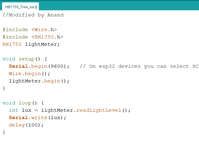
Arduino code of BH1750 for Processing interface.
Initially I used the BH 1750 (Light sensor) Arduino code for programming the ESP32 board.The programming code is given in the Input Devices assignment.For used of processing interface I have made small changes in the program as shown in the image.
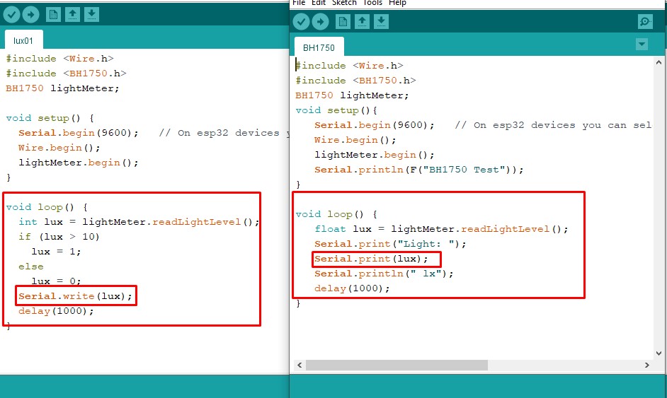
Changes made in Arduino code.
In the given two program used the same libraries,initized the same function in the void setup only change the void loop.For normal output on serial monitor use the "Float Lux" means decimal value and used "Serial .Print(Lux)" for displaying the decimal value on serial monitor in ASCII (Human readable)format.
But in the prsent modified program for output use "Int Lux " means integer value , also used if conditon in which if lux value is greater than 10 put lux is equal to 1 eals put 0.used "Serial.write(Lux)" for displaying digital value(Machine readable) which is used for processing output.The modified program is given below.
#include "Wire.h"
#include "BH1750.h"
BH1750 lightMeter;
void setup() {
Serial.begin(9600); // On esp32 devices you can select SCL and SDA pins using Wire.begin(D22,D21);
Wire.begin();
lightMeter.begin();
}
void loop() {
int lux = lightMeter.readLightLevel();
if (lux > 10)
lux = 1;
else
lux = 0;
Serial.write(lux);
delay(1000);
}
Processing interface change the color of rectangle.
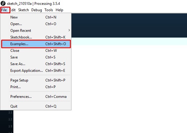
The processing interface of the modified Arduino code with change the colour of rectangle is given below.For this use the simple Read example.
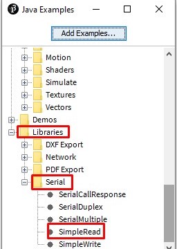
Open the processing window.Go to==>File==>Example==>Library==>Serial==>Serial Read.
The simlpe read code is open.
/**
* Simple Read
* Modified by Anand*/
import processing.serial.*;
Serial myPort;
int val;
void setup()
{
size(200, 200);
String portName = Serial.list()[0];
myPort = new Serial(this, portName, 9600);
}
void draw()
{
if ( myPort.available() > 0) {
val = myPort.read();
}
background(255);
if (val == 0) {
fill(0);
} else {
fill(204);
}
rect(50, 50, 100, 100);
}
- import processing.serial.* => It Include the library for serial communication.
- Serial myPort => Create an obect from serial class
- int val => data received from serial port.
- String portName = Serial.list()[0] => Open the serial port list and connect with first.
- myPort = new Serial(this, portName, 9600) => Open the port you are using at the rate you want
- void draw() => it work as void loop.
- In the If condition if data is available read it and store in the value.
- background(255) => Set the white background
- if (val == 0) fill(0); => If the value is 0 set rectangle with blak
- else { fill(204) => If the value is 1 set the rectangle light gray.
- rect(50, 50, 100, 100) => it gives the size of rectangle.
The parts of the program can be explain as follows.
Output of Processing interface.
As the light intensity changes there is change in rectangle colour as shown in below.
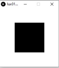
When light intensity is less than 10lux
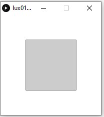
When light intensity is greater than 10lux.
The processing output as shown in video
Processing interface Renders as simple tree.
I have made small change in the original arduino code of BH 1750 (Light sensor).The Arduino code is given below.
arduino code of BH 1750 (Light sensor)
In this code there is small chang e in the void loop i.e used "Serial.write(Lux)"and "delay(100)".
Code for Renders as simple tree.
Open the processing window.Go to==>File==>Example==>Topics==>fractals and L-systems==>Tree.
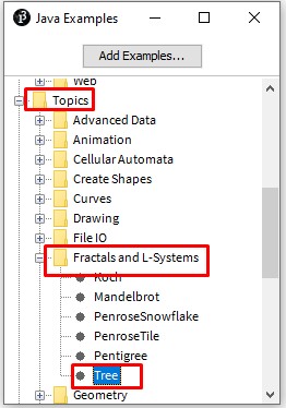
The processing tree code is open.
float theta;
void setup() {
size(640, 360);
}
void draw() {
background(0);
frameRate(30);
stroke(255);
// Let's pick an angle 0 to 90 degrees based on the mouse position
float a = (mouseX / (float) width) * 90f;
// Convert it to radians
theta = radians(a);
// Start the tree from the bottom of the screen
translate(width/2,height);
// Draw a line 120 pixels
line(0,0,0,-120);
// Move to the end of that line
translate(0,-120);
// Start the recursive branching!
branch(120);
}
void branch(float h) {
// Each branch will be 2/3rds the size of the previous one
h *= 0.66;
// All recursive functions must have an exit condition!!!!
// Here, ours is when the length of the branch is 2 pixels or less
if (h > 2) {
pushMatrix(); // Save the current state of transformation (i.e. where are we now)
rotate(theta); // Rotate by theta
line(0, 0, 0, -h); // Draw the branch
translate(0, -h); // Move to the end of the branch
branch(h); // Ok, now call myself to draw two new branches!!
popMatrix(); // Whenever we get back here, we "pop" in order to restore the previous matrix state
// Repeat the same thing, only branch off to the "left" this time!
pushMatrix();
rotate(-theta);
line(0, 0, 0, -h);
translate(0, -h);
branch(h);
popMatrix();
}
}
In this basic tree code I have made the change as shown below.In this code the tree changes its shape as we move the mouse, while in my code with the movement of light source the tree will changes its shape.
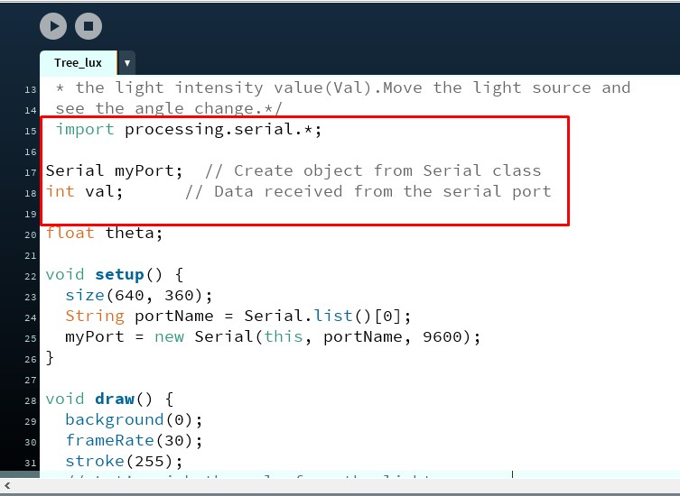
- import processing.serial.* => It Include the library for serial communication.
- Serial myPort => Create an obect from serial class
- int val => data received from serial port.
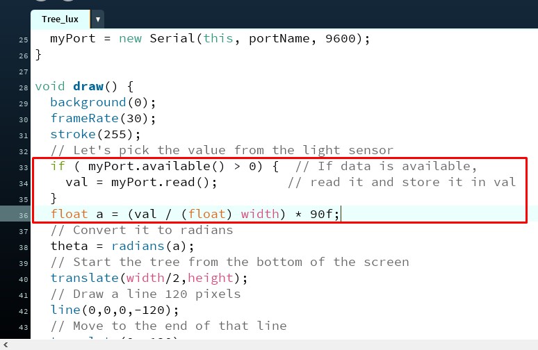
- if ( myPort.available() > 0){val = myPort.read(); } => If date is available read it and store it in the value.
- float a = (val / (float) width) * 90f => replace the value in place mousex in given program
The modified code is given below.
/**
*Modified By Anand
*The branching angle is calculated as a function of
* the light intensity value(Val).Move the light source and
see the angle change.*/
import processing.serial.*;
Serial myPort; // Create object from Serial class
int val; // Data received from the serial port
float theta;
void setup() {
size(640, 360);
String portName = Serial.list()[0];
myPort = new Serial(this, portName, 9600);
}
void draw() {
background(0);
frameRate(30);
stroke(255);
// Let's pick an angle 0 to 90 degrees based on the Lux value.
if ( myPort.available() > 0) { // If data is available,
val = myPort.read(); // read it and store it in val
}
float a = (val / (float) width) * 90f;
// Convert it to radians
theta = radians(a);
// Start the tree from the bottom of the screen
translate(width/2,height);
// Draw a line 120 pixels
line(0,0,0,-120);
// Move to the end of that line
translate(0,-120);
// Start the recursive branching!
branch(120);
}
void branch(float h) {
// Each branch will be 2/3rds the size of the previous one
h *= 0.66;
// All recursive functions must have an exit condition!!!!
// Here, ours is when the length of the branch is 2 pixels or less
if (h > 2) {
pushMatrix(); // Save the current state of transformation (i.e. where are we now)
rotate(theta); // Rotate by theta
line(0, 0, 0, -h); // Draw the branch
translate(0, -h); // Move to the end of the branch
branch(h); // Ok, now call myself to draw two new branches!!
popMatrix(); // Whenever we get back here, we "pop" in order to restore the previous matrix state
// Repeat the same thing, only branch off to the "left" this time!
pushMatrix();
rotate(-theta);
line(0, 0, 0, -h);
translate(0, -h);
branch(h);
popMatrix();
}
}
Output of Processing interface.
As the light source is moving towards or away there is change in the shape of the tree.
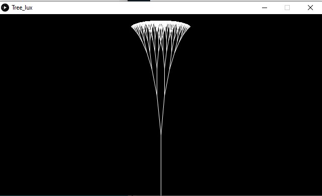
when Lux value is small.
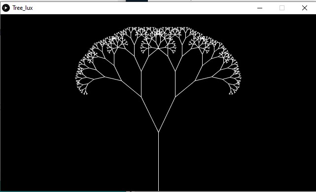
when Lux value is large.
The processing output as shown in video
About MIT App Inventor
MIT App Inventor is a web application integrated development environment originally provided by Google, and now maintained by the Massachusetts Institute of Technology (MIT). It allows newcomers to computer programming to create application software(apps) for two operating systems (OS): Android, and iOS, which, as of 8 July 2019, is in final beta testing. It is free and open-source software released under dual licensing: a Creative Commons Attribution ShareAlike 3.0 Unported license, and an Apache License 2.0 for the source code. It uses a graphical user interface (GUI) very similar to the programming languages Scratch (programming language) and the StarLogo, which allows users to drag and drop visual objects to create an application that can run on android devices, while a App-Inventor Companion (The program that allows the app to run and debug on) that works on iOS running devices are still under development. In creating App Inventor, Google drew upon significant prior research in educational computing, and work done within Google on online development environments.(Wikipedia)
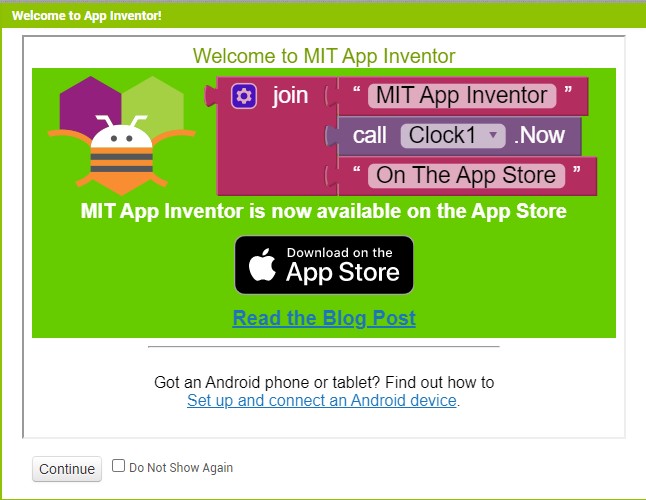
Opening window of MIT App Inventor MIT App Inventor
MIT App Inventor Interface.
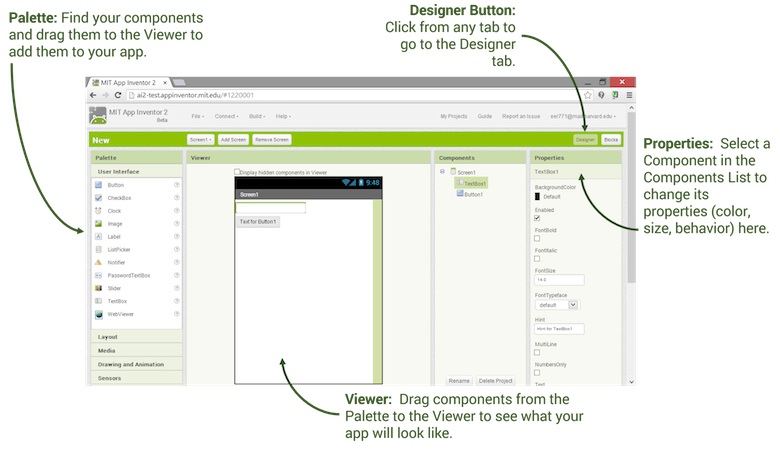
MIT App Inventor designer window
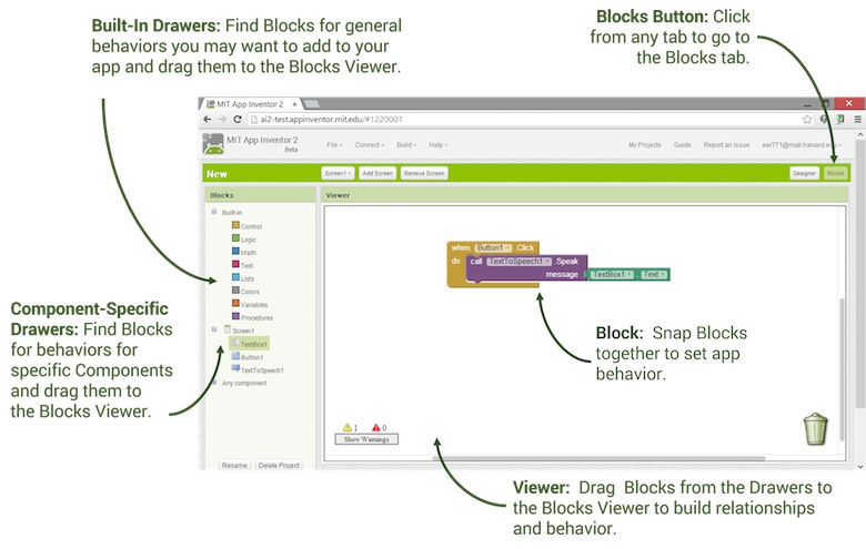
MIT App Inventor Block programming window
Use TUNIOT for programming ESP32 as Web server.
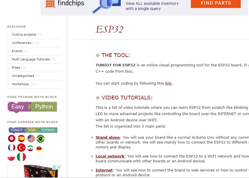
About TUNIOT
- TUNIOT FOR ESP8266
- TUNIOT FOR ESP32
TUNIOT is a code generator for the ESP8266\ESP32 boards. You don’t need any coding skills to program it and make your IoT project. The tool is available on 7 languages and in active development and documentation is available!There is several resources in different language to learn ESP8266\ESP32 and program in blocks mode.There is 2 versions of the program:
Programming ESP32.
For programming the ESP32 MCU as web server I follow the tutorial "Controlling SEP32 with an android app over Wi-Fi" given by ADEL KASSAH.The detail of the block programming is given below.
Goto TUNIOT through the web browser.
- The TUNIOT page is open.
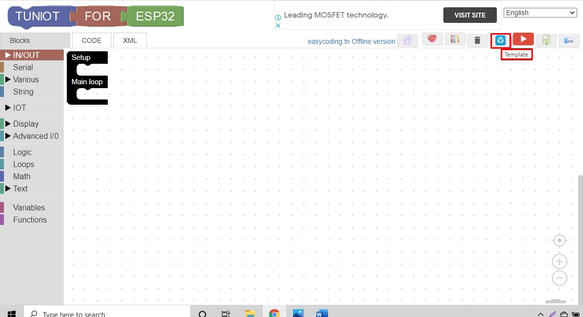
- Go to TUNIOT of ESP32.
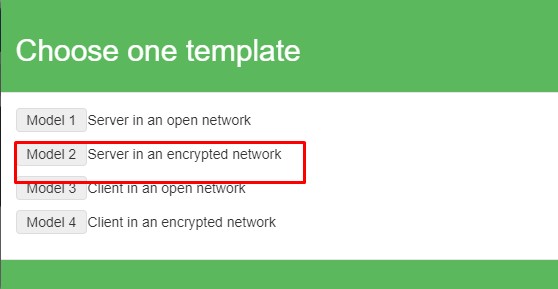
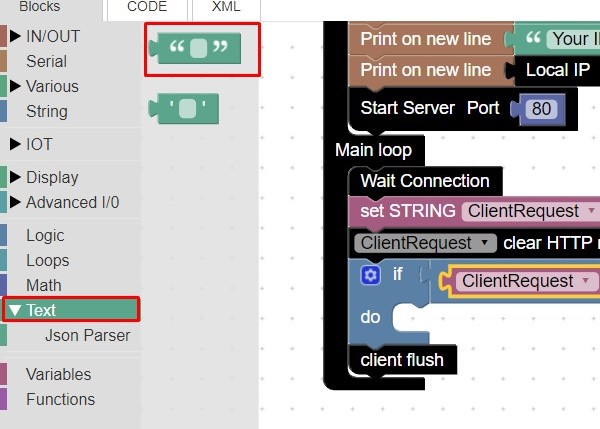
- TUNIOT for ESP32 programming page is open.Goto the top right corner select the "Templete."
- Choose the Modeel-2"Server in ancrypted network."
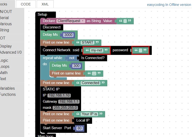
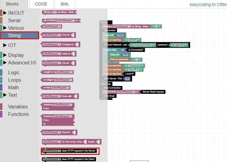
- the block program is open.Update the Network ssid and password in the program.
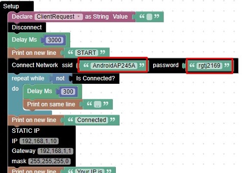
- the Network ssid and password is updated.
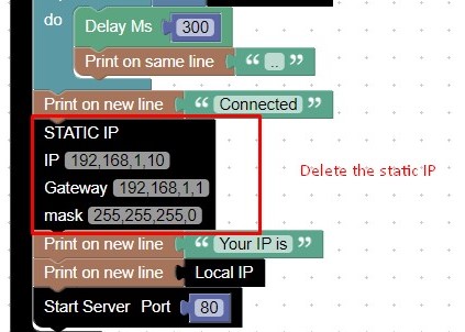
- Delete the static IP given in the program.
- Got to string and select the "Client request block" for clearing HTTP request in server.
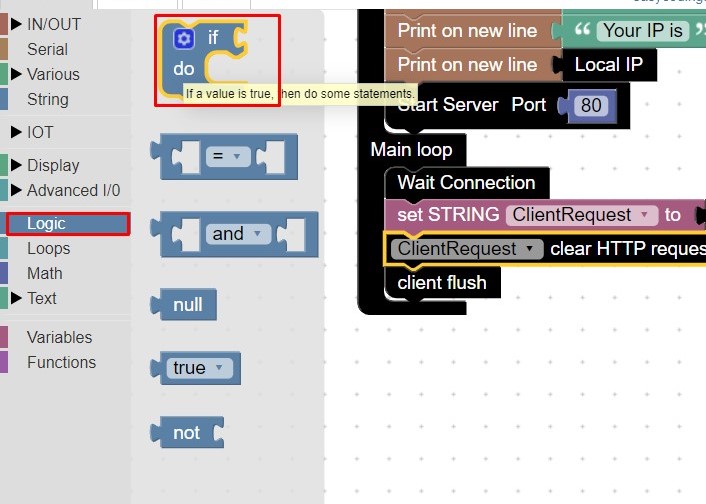
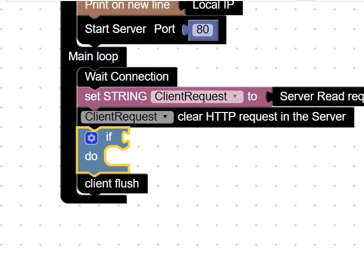
- Add the client request block. Goto Logic select If and do block.Also select return true value block.
- Adding logic block in tne programming.
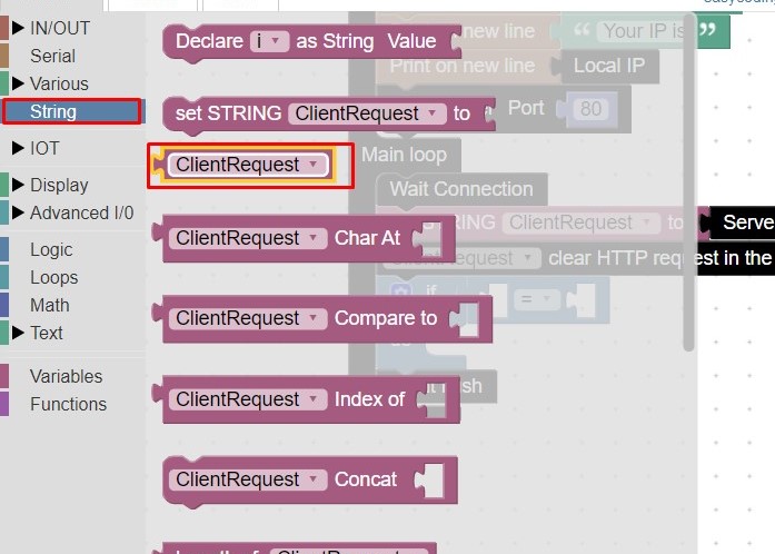
- Go to string select the "Client request" block.
- Adding "Client request" and "Text" block in the "If" side of block and update text as "on".
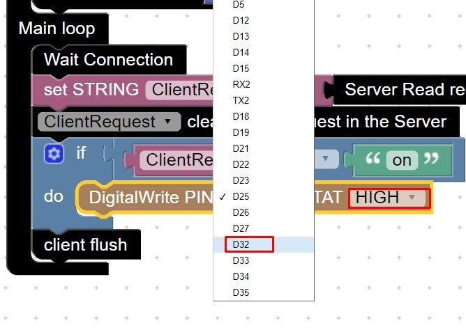
- Goto Input digital ,select the Digital write pin block.
- Update the digital pin numeber, and its state at high.
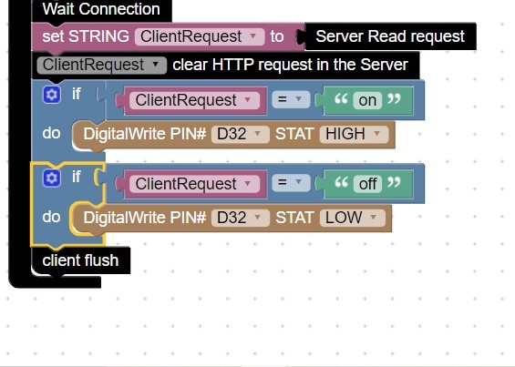
- Make the duplicate of logic block change the client request"Off" and pin state low.
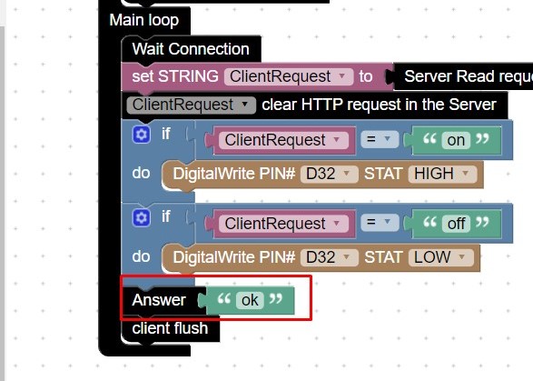
- Goto IOT,IOT server select answer block added with text ok.
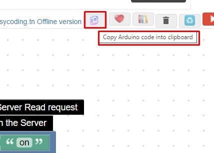
- Now copy the Arduino code in to clipboard.


Now paste the code in the Arduino sketch as given below.
//Modified by Anand
//07/05/2021
//Smart Azolla Multiplier system
//Running Exahust fan
#include "WiFi.h"
String ClientRequest;
WiFiServer server(80);
WiFiClient client;
String myresultat;
String ReadIncomingRequest(){
while(client.available()) {
ClientRequest = (client.readStringUntil('\r'));
if ((ClientRequest.indexOf("HTTP/1.1")>0)&&(ClientRequest.indexOf("/favicon.ico") 0))
{
myresultat = ClientRequest;
}
}
return myresultat;
}
void setup()
{
ClientRequest = "";
Serial.begin(9600);
pinMode(32, OUTPUT);
WiFi.disconnect();
delay(3000);
Serial.println("START");
WiFi.begin("AndroidAP245A","rgtj2169");
while ((!(WiFi.status() == WL_CONNECTED))){
delay(300);
Serial.print("..");
}
Serial.println("Connected");
Serial.println("Your IP is");
Serial.println((WiFi.localIP()));
server.begin();
}
void loop()
{
client = server.available();
if (!client) { return; }
while(!client.available()){ delay(1); }
ClientRequest = (ReadIncomingRequest());
ClientRequest.remove(0, 5);
ClientRequest.remove(ClientRequest.length()-9,9);
if (ClientRequest == "on") {
digitalWrite(32,HIGH);
}
if (ClientRequest == "off") {
digitalWrite(32,LOW);
}
client.println("HTTP/1.1 200 OK");
client.println("Content-Type: text/html");
client.println("");
client.println("");
client.println("");
client.println("ok");
client.println("");
client.stop();
delay(1);
client.flush();
}
Now compile the code and output is display on the serial monitor shown below.
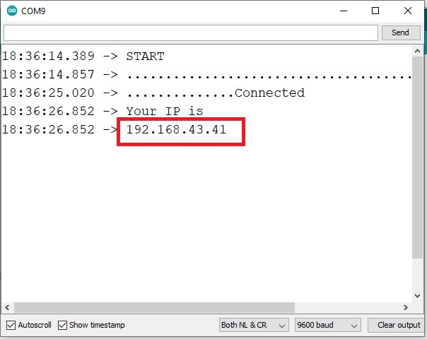
IP address of ESP 32.
The output of the serial monitor display the IP address of the ESP32.Copy the IP address,paste it in the web browser confirmation purpose.if we type IP address/on it will displayed Ok on the page,als if we type IP address/ off it will displayed Ok on the web page.it shows that ESP32 work as web server.
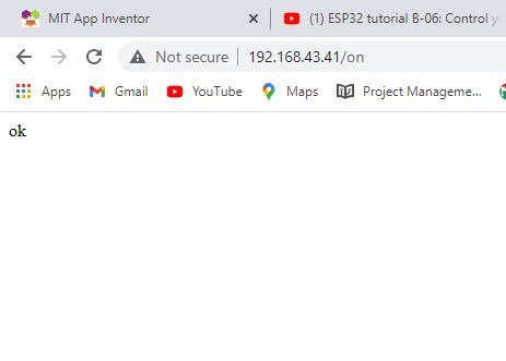
IP address with on condition.
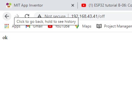
IP address with off condition.
Used MIT App Inventor for creating Mobile Application.
Now I have to operate the ESP32 MCU through mobile app.As I am using exahust fan as output device, I am trying to operate it by mobile app.so for making the mobile app go through folowing procedure.
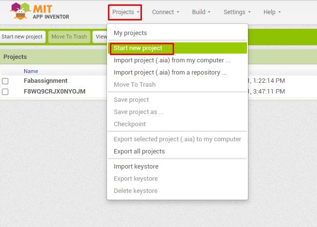
- Open the MIT app Inventor designer window,goto the Project select new project.
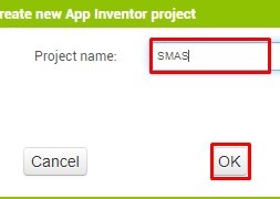
- Enter the project name, click ok.
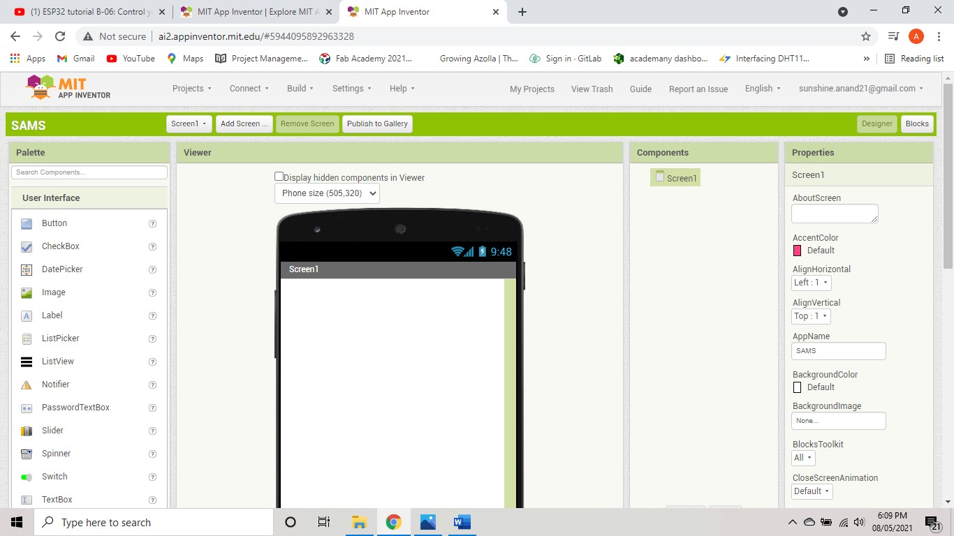
- App Inventer designer window is open with the name of project.
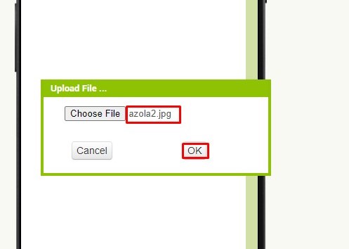
- For change the back ground ,goto properties => Background image =>Choose file. Uplod it
- The back ground image changes.
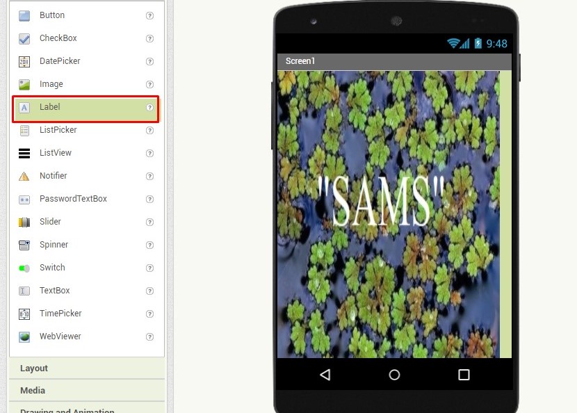
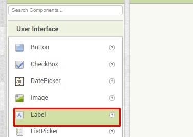
- For my app I used two labels.Goto pallete,user interface select label.
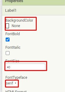
- From the property,you change Bcakground color,font size, font type height.
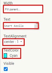
- you can also change width,text,textalignment,textcolor.
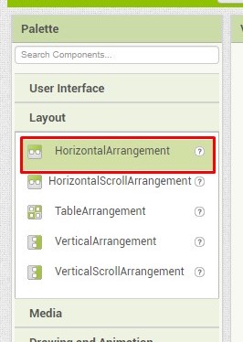
- From the pallete,layout select Horizontal arrangement for placing buttons.
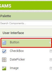
- For operating the fan select two buttons from pallete,user interface.
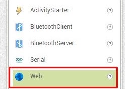
- For web connectivity,select Web from pallete, connectivity.
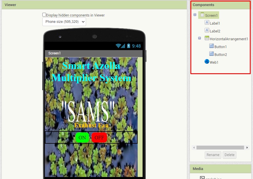
- The app interface with all the components as shown in the image.
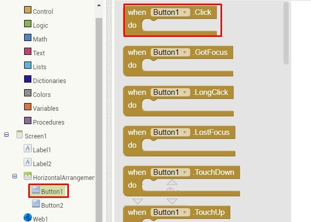
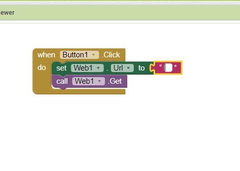
- Now for programming switch to the block window.Goto Button1 select click button block.
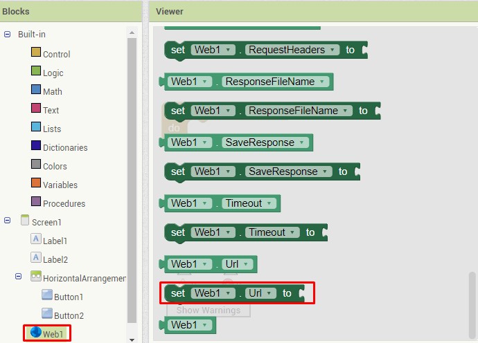
- Goto Web1 select the "set Web1 url" block.
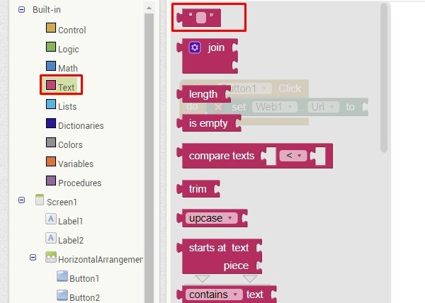
- Goto text select the text block.
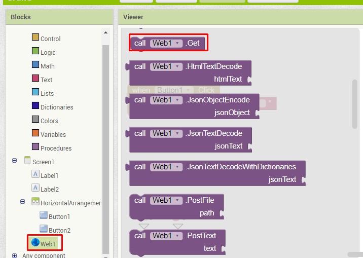
- Goto web1 select "call web1 get" block.
- Adding all the blocks in the viewer as shown below
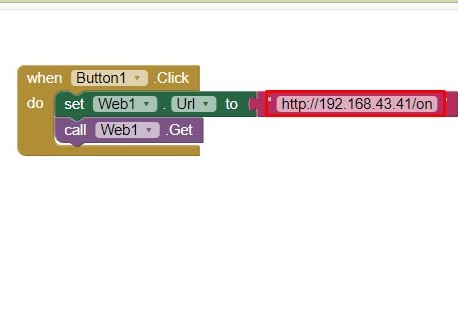
- Now copy the IP address of the ESP32 with on condition and add it program text block.
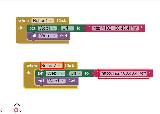
- Write same code for Button 2 only change with the off condition.
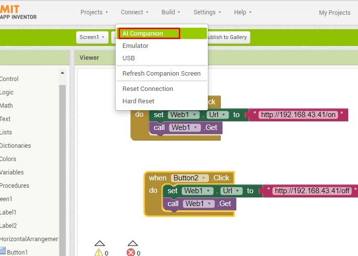
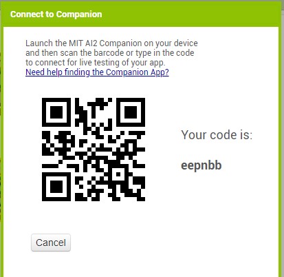
- Now the block code is ready,goto connect, select Al companion.
- The bar code is open,scan the bar code through "MIT AI2 Companion"
In the below image we can see the application on the operating screen as well as on mobile screen. This will make the provision of operating the fan by using our android devices.
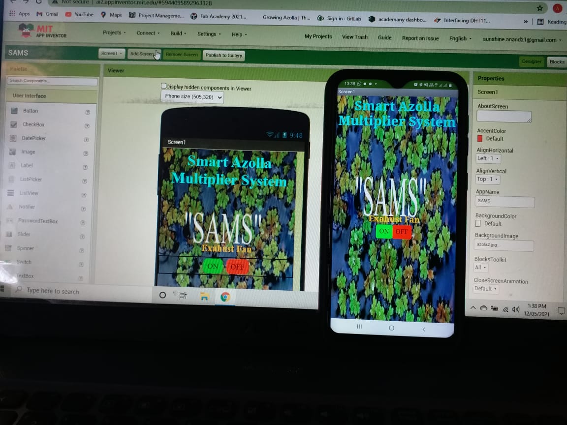
SAMS mobile app.
The exahust fan on and off using mobile app as shown in video
Learning Outcomes
- I introduced with diffrent GUI.
- Used Processing for interfacing the BH 1750(light sensor) reading.
- Used MIT App Inventor for creating Mobile app.
- Operating the output device using mobile app.
- Used TUNIOT for writing the code for ESP32 web server
Downloads
SAMS-Smart Azolla Multiplier System by Anand S. Tale is licensed under CC BY-SA 4.0![]()
![]()
![]()