4. Computer-Controlled Cutting
Learnings from last week
I feel like I am still lacking organisations. So I’ll try to improve my organisations this week.
-
Study Plan :
-
Assignment definition: What do I have to do for next week ?
- What do I know already ?
- What do I want to learn ?
- What time will I dedicate to each topic ?
-
What do I want to build by the end of the week ?
-
Research : Covering the core topic of the lesson what did I try as tools, what did I read related to the subject
Study Plan
Assignment definition
Group assignment
Characterize your lasercutter’s focus, power, speed, rate, kerf, and joint clearance Document your work (individually or in group)
Individual assignments
Design, lasercut, and document a parametric press-fit construction kit, which can be assembled in multiple ways. Account for the lasercutter kerf. cut something on the vinylcutter
Learning outcomes
- Demonstrate and describe parametric 2D modelling processes
- Identify and explain processes involved in using the laser cutter.
- Develop, evaluate and construct the parametric construction kit
- Identify and explain processes involved in using the vinyl cutter.
Have you
- Linked to the group assignment page
- Explained how you parametrically designed your files
- Documented how you made your press-fit kit
- Documented how you made your vinyl cutting
- Included your original design files
- Included your hero shots
What do I know already ?
I know you need svg files to cut stuff and you can engrave raster files likes images with the laser cutter but that’s it.
What do I want to learn ?
- Refine my learning process and my organisation
- Make construction kits : Boxes and “statues”
- 2D Parametric modelling : I did not dive deep enough last week so I want to do it properly this week !
- Learn to use the Vynil cutter, the required files, how to adapt the parameters
- Learn to use the laser cutter, the required files, how to adapt the parameters
What do I want to build by the end of the week ?
- Cut a board game
- Make a T-shirt
- Make construction kits : Boxes and “statues”
- Create my personal workflow for vynil cutter and laser cutting
- Improve my documentation process
Laser Cutting
Notes from the course:
- Pay attention to laser kerf. You don’t want to cut to close or you lose part of your design.
- Design and test multiple joints
Process
Last week, I was not happy with my learning process so I decided to start from the reference.
I directly set a time with Quentin to meet at the lab and I started reading the slides of tutorial on the FabAcademy website for laser cutting.
Theoretical intro
Be safe !
- Class 1 laser cutters are safe the rest you have to pay a lot more attention to it.
- Laser cutters want to burn themselves, so stay close to them !
1. Materials
- Non reflective
- Thickness dependent on the power of the machine
- Safety : PVC is forbidden, it is dangerous and damages the machine
- Ask the lab
2. Kerf
The kerf is the width of material removed during the cutting process, you have to measure it for your set of parameters because it depends on many parameters, even the direction of the laser head (X or Y).
It is especially important for press-fit applications.
We can measure it with precision by cutting multiple times a piece of which we know the original length.
We compare the sum of the cut pieces with the original size and divid that by the number of cuts and we have the kerf.
We looked at it in our lab. Our hypothesis is that the kerf is symetrical, so we lose half a kerf on the cut piece and the other half is lost on the base material.
Group Assignment
We documented the calibration in group here.
Materials
Overall, I tested different materials:
- different thin wood planks
- cardboard for first prototypes
- PMMA / Acrylic for transparent support
Learnings on materials
Cardboard is much better than I expected both for prototyping and also for lightweight applications that do not fear water or require high mechanical performance.
When laser cutting wood, it’s important to choose one that gets cut “cleanly” a lot of woods aggregate contain lots of glu which can make your cuts dirty, create toxic fumes and get the lens dirty.
Cutting PMMA with a laser cutter is amazing ! The cut is really beautiful and really smooth ! I love it !
Designing a construction kit
First try : FreeCAD
I started out with FreeCAD. I want to domesticate it and create my CAD files with a free software.
First, I set up the slots.
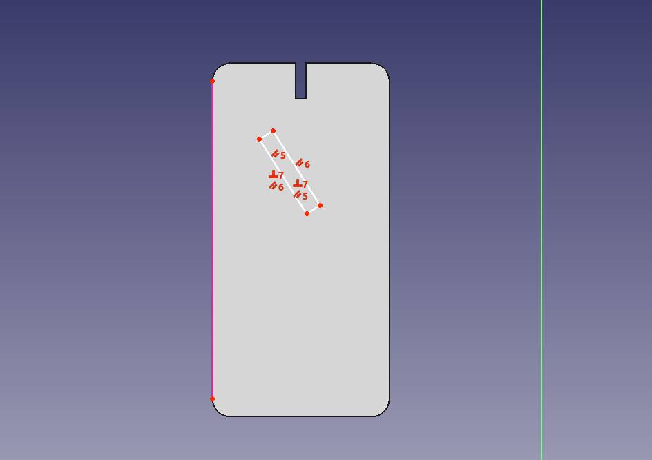
Then prepared the spreadsheet with as many parameters as I thought would be useful.
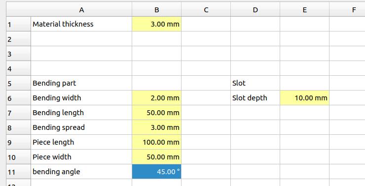
FreeCAD option were inconvenient so I looked for a way to import spreadsheets and found it.
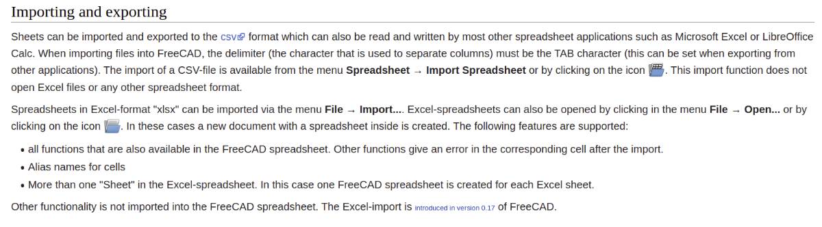
But it was also inconvenient as the excel functions were not supported in FreeCAD spreadsheets… I tried to do some trigonometry and realized I had gotten super extra slow…
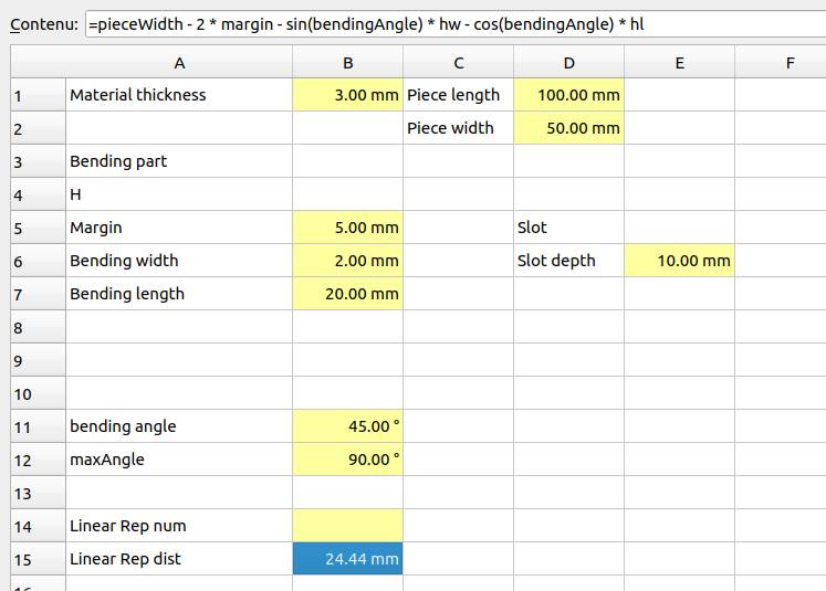
and finally I got stuck…
I was super frustrated not to be able to do linear pattern in more than one directions and not to be able to apply linear patterns to another linear pattern.
Having given a lot of effort to it, I decided to revert as planned to Fusion360. I then tried to reinstall Windows on my computer (that only runs Ubuntu) and it was a nightmare, I tried for 1,5 days and could not manage it so I decided to go for OnShape.
Designing the construction kit : Onshape
Onshape is online and on top of that, my computer does not have a graphics card, so i expected it to be a mess.
I wanted to design a generic kit and then design a lamp.
1. The construction kit
I took inspiration from the kit of a fellow student during the Global Open Time.
For the construction kit, I wanted a connector piece with angles, simple straigth ones short and long and then flexible ones, circular and helicoidal.
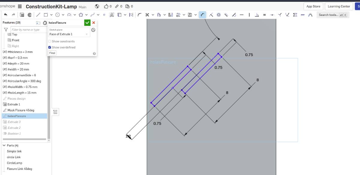
In kind of a stupid way, I started by 45° flexure and I tried to make it completely automatic using a mask then boolean operations but combining the low computing power of my computer and the very bad design I had made it froze it and I stopped.
As I expected it was very slow to compute to the point that I don’t really know if it is bugged or still computing.
I tried to change the orientation of the linear patterns to limit it to the piece and not beside it. Unfortunately, I did not find a set of parameters that kept a similar pattern vertically.
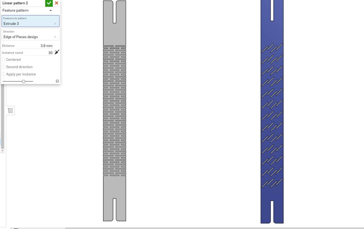
I finally managed to do an angled flexure piece but I realized that the non cut margin on both sides would prevent it from bending so I redrew it.
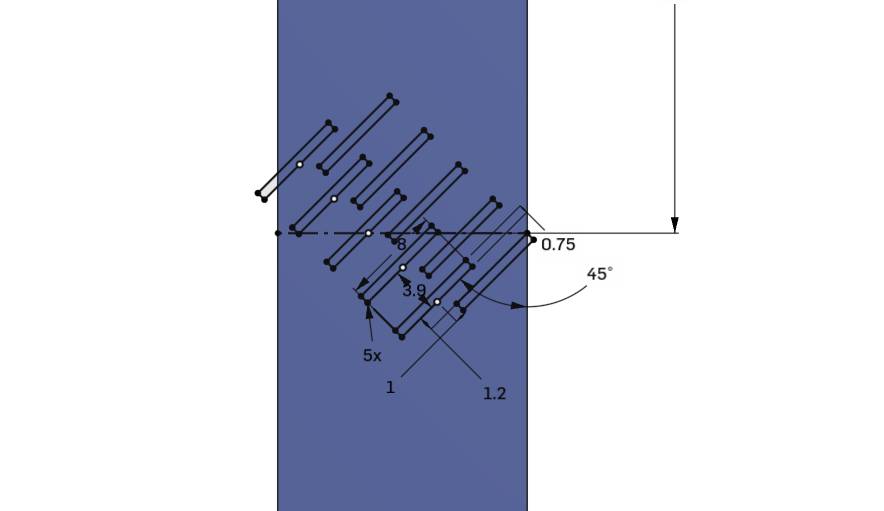
I took me a lot of trial and error to get to the result without freezing the computer and actually delivering but I got it.

The simple circular flexure link was much easier to draw, fortunately !
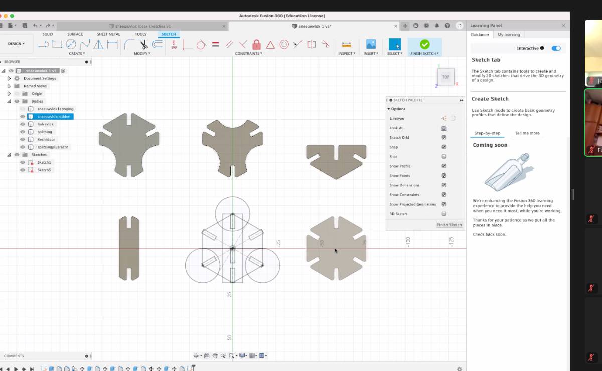
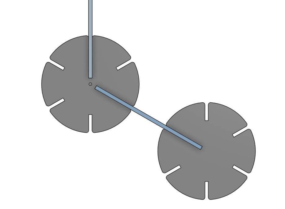
So I had my kit, and looking at it, it seems to be functional.
I wanted to check it in action before printing it so I went to the assembly mode. It looks nice but …
There is some overlap at the center of the disk piece !
That is no problem, thanks to parametric design I just had to change one value to get it working !
2. The Lamp construction kit
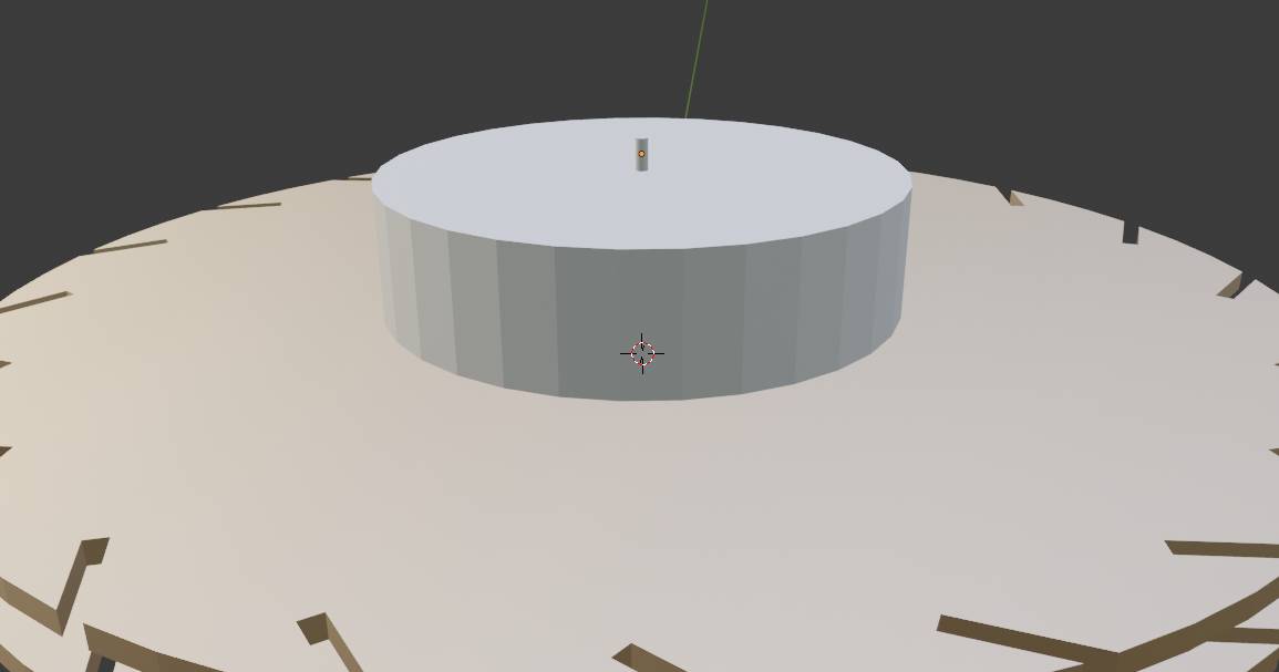
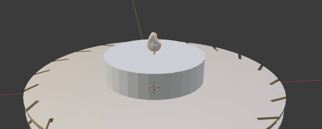
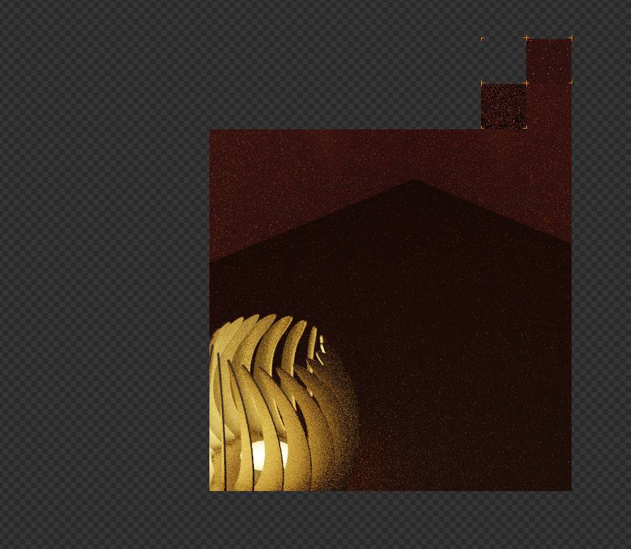
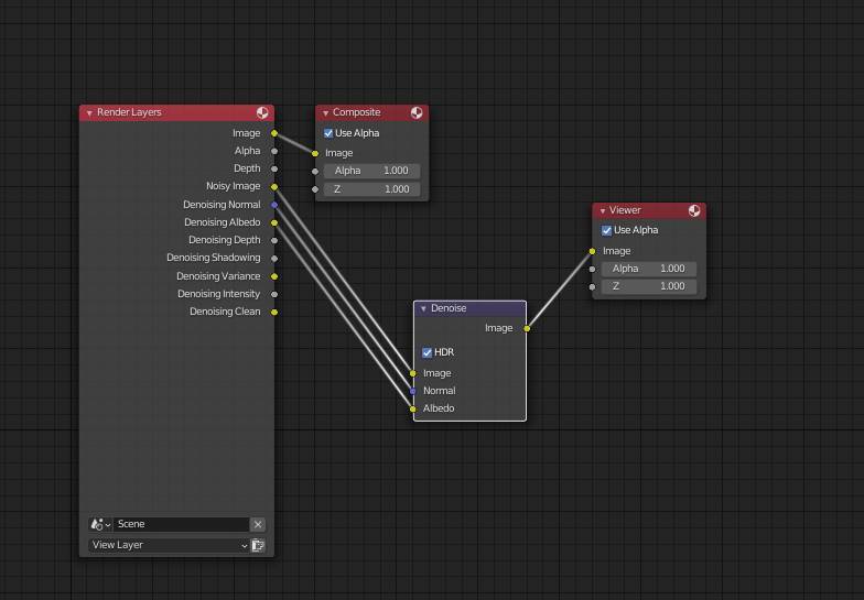
I found some inspiration online for laser cut lampshades, so i decided to make one and render it in blender before cutting it as I want to practice my new skills !
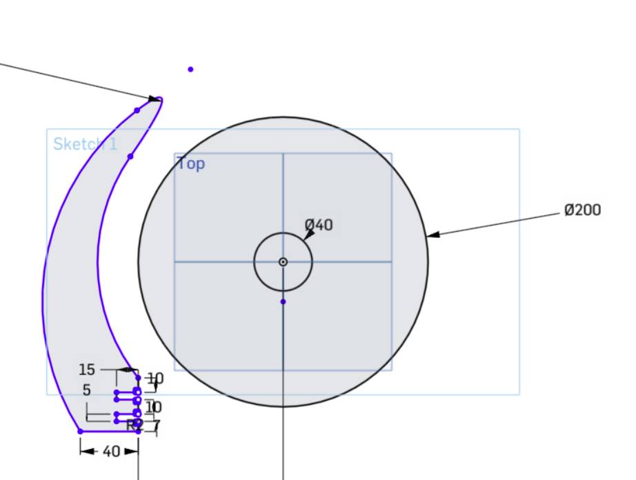
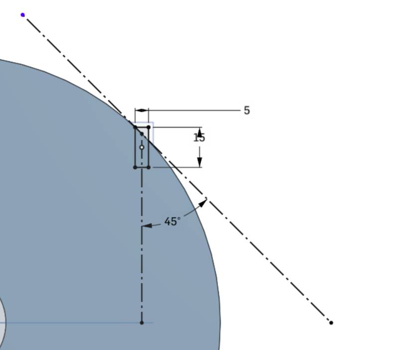
Lets start designing in Onshape !
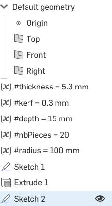
To include the kerf, I know that 1 cut takes away half of the kerf as I suppose it’s a symmetrically centered cut. Therefore the depth of my slots are wider than expected by 0.5 times the kerf for each cut. We have two so I need to subtract a full kerf to the dimensions of the slot.
Actually, I also use the kerf parameter as a tuning parameter for the fit to be perfect.

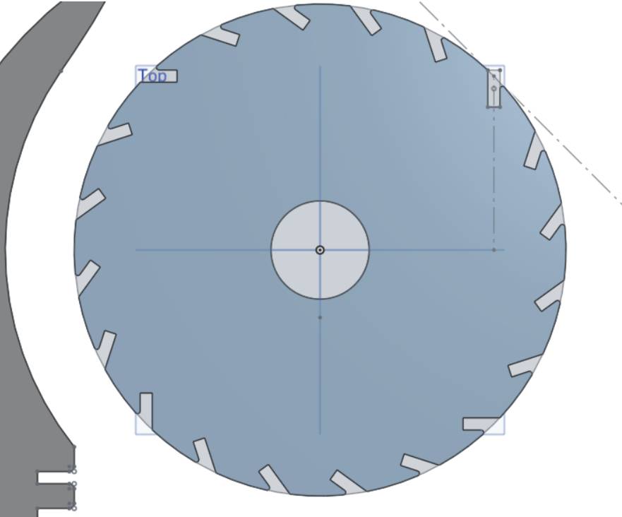
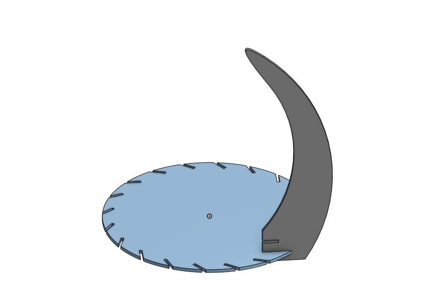
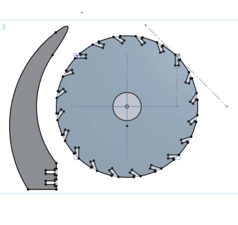
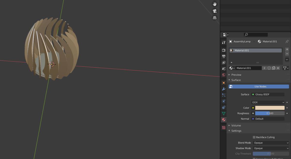
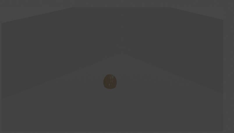

And here is the result !
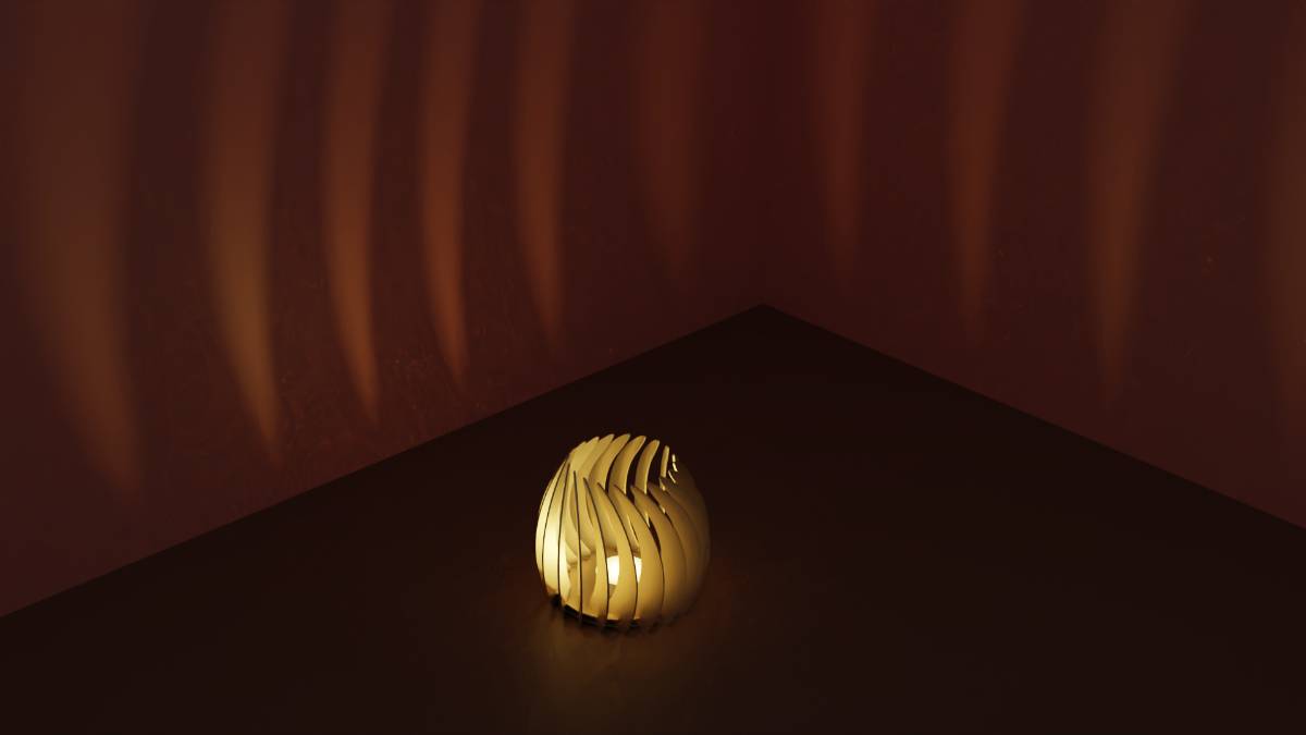
I am quite happy as it was very fast to do after the trouble of last week !
Ok now lets see how to make it !
Cutting and testing
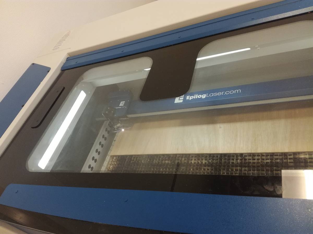
First I prepared the material, cutting the available planks to fit in our Epilog laser cutter.

Then let’s start cutting !
1. Construction kit
Having measured the kerf (0.3mm) and the thickness of our material (5.2mm), I started cutting and it went perfectly !

2. Lamp kit
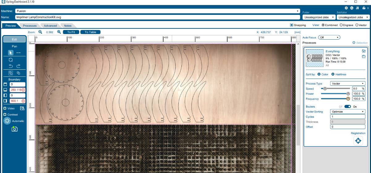
I started by cutting the lamp but there was a problem translating the DXF from onshape to SVG for Inkscape.

I fixed the file transfer (just clicking manual scale did the trick) and veryfing one reference length in Inkscape.
I started cutting the 20 blades I needed and the cut was very good at in some parts of the plank but not complete in others. I guess the plank was not perfectly flat and thus the laser was slightly out of focus in some part of the plank.
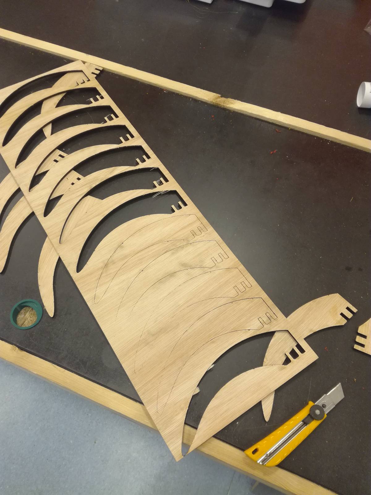
I passed some cuts with a cutter and detach the blades and took them home.
|
|

|

|
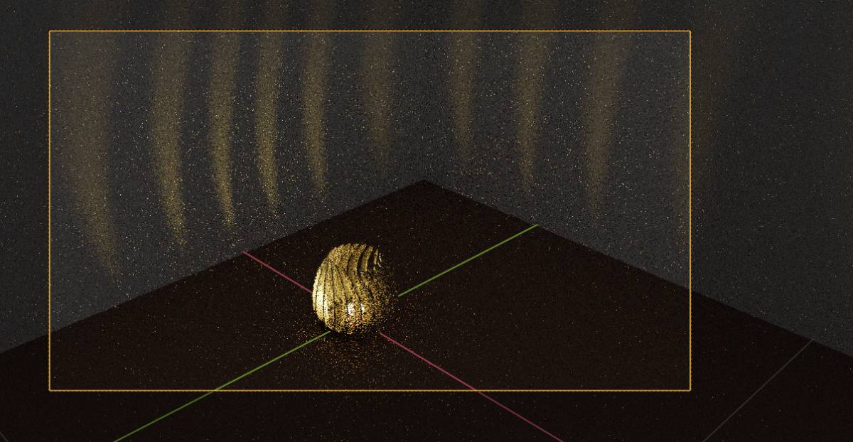
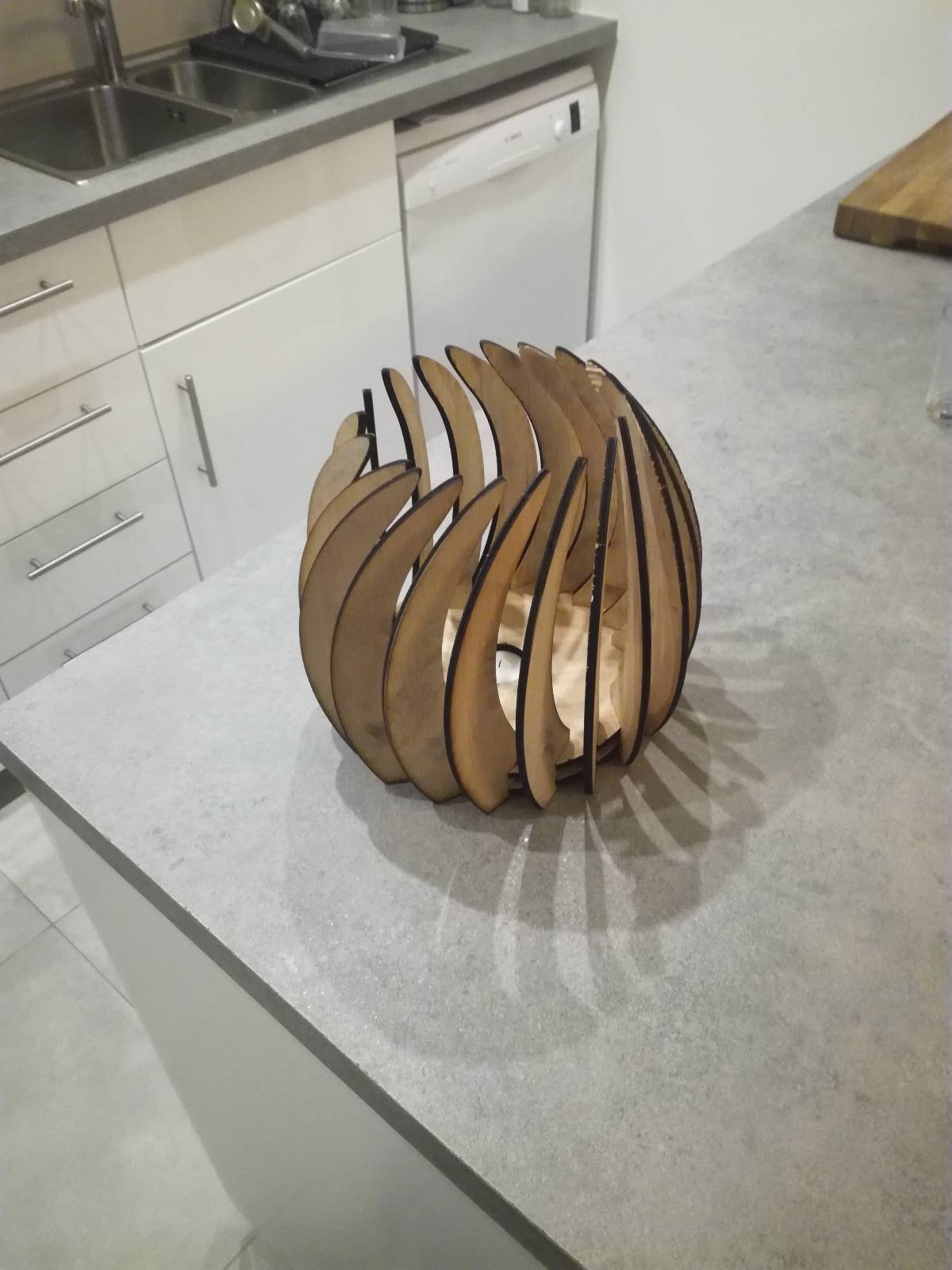
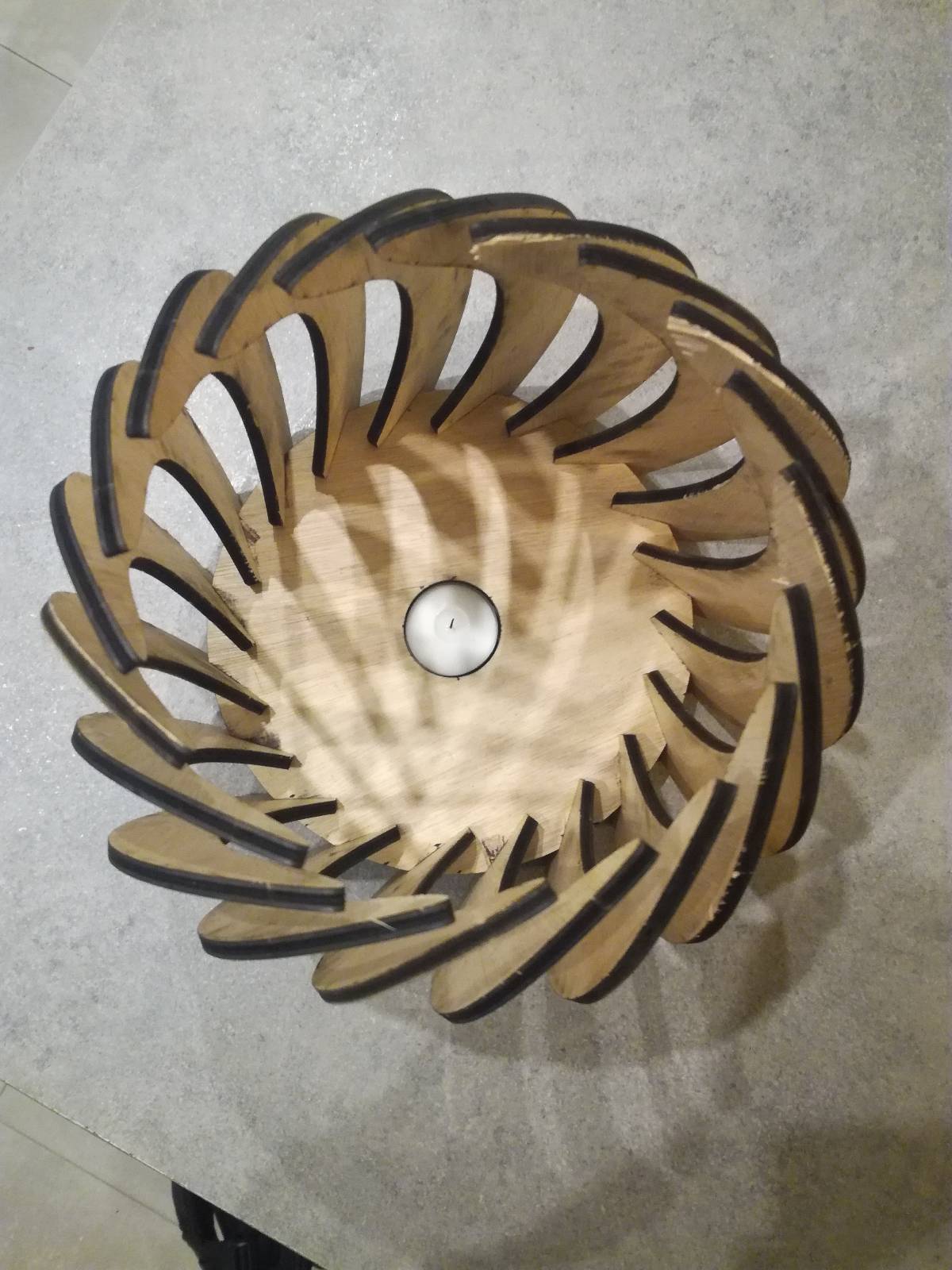
Now let’s compare apples with apples, the rendering and the real lamp with a candle :
|
|
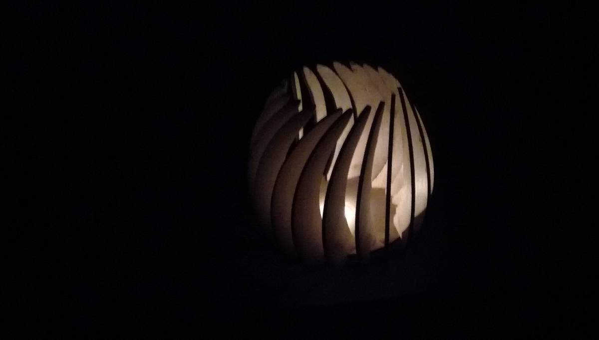
|
The rendering is very close to the real deal ! I consider this a high success !!
Vynil Cutter
The parameters change all the time thus the parametric design is crucial. You always should try your parameters and make a test run before the real thing.
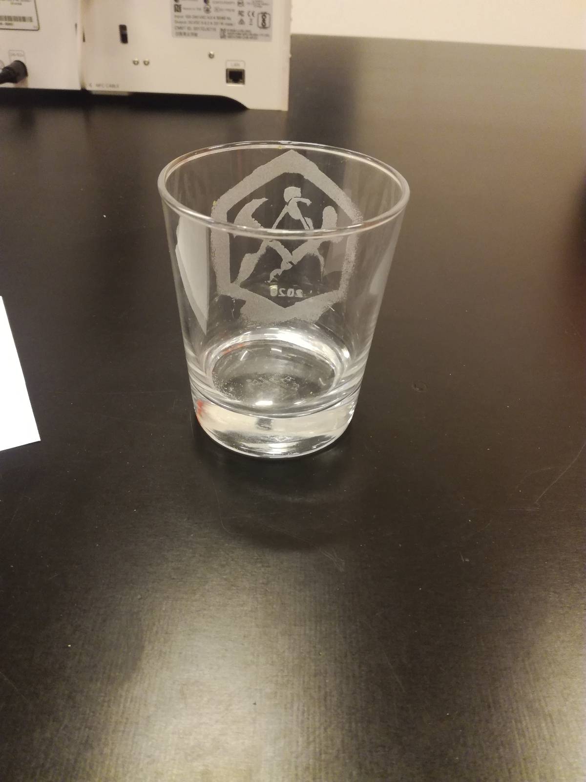
I worked mainly with the laser cutter this week but I wanted to try to do something cool with the Vynil cutter too so I decided to sandblast the university logo. We had done a first test with Maxime but the result were not completely satisfactory so I tried on my own.
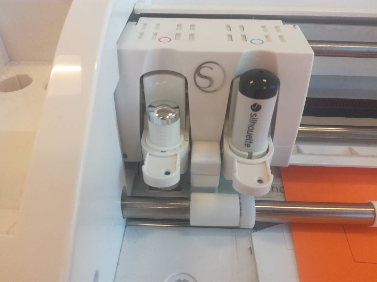
First, here is our machine :
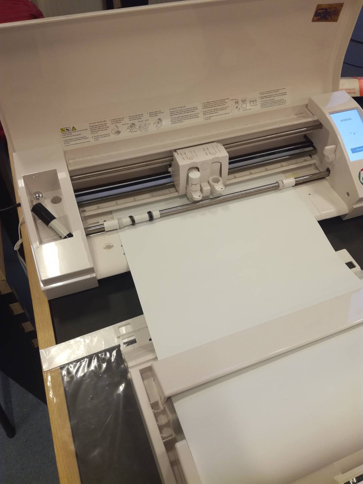
It is very intuitive to use ! Off course, as always, it’s important to test the parameters.
The first thing is to load the support mat, using the integrated interface.
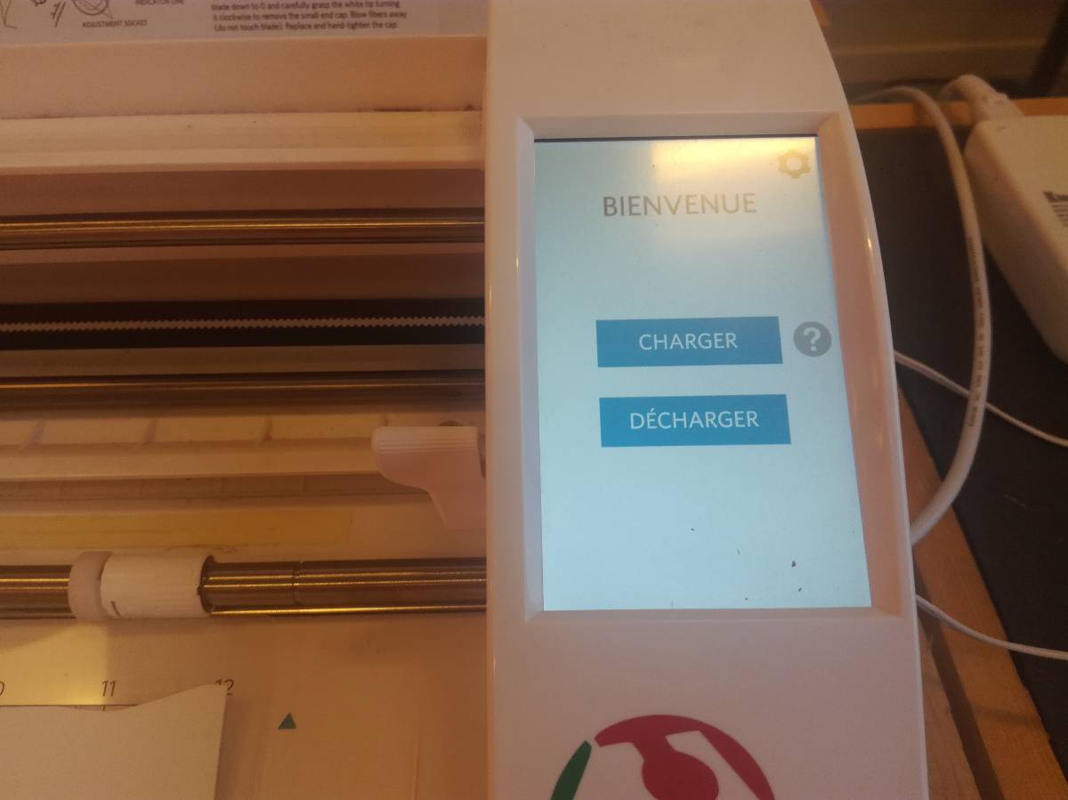
Then in the interface, you can draw and define different type of line using different settings.
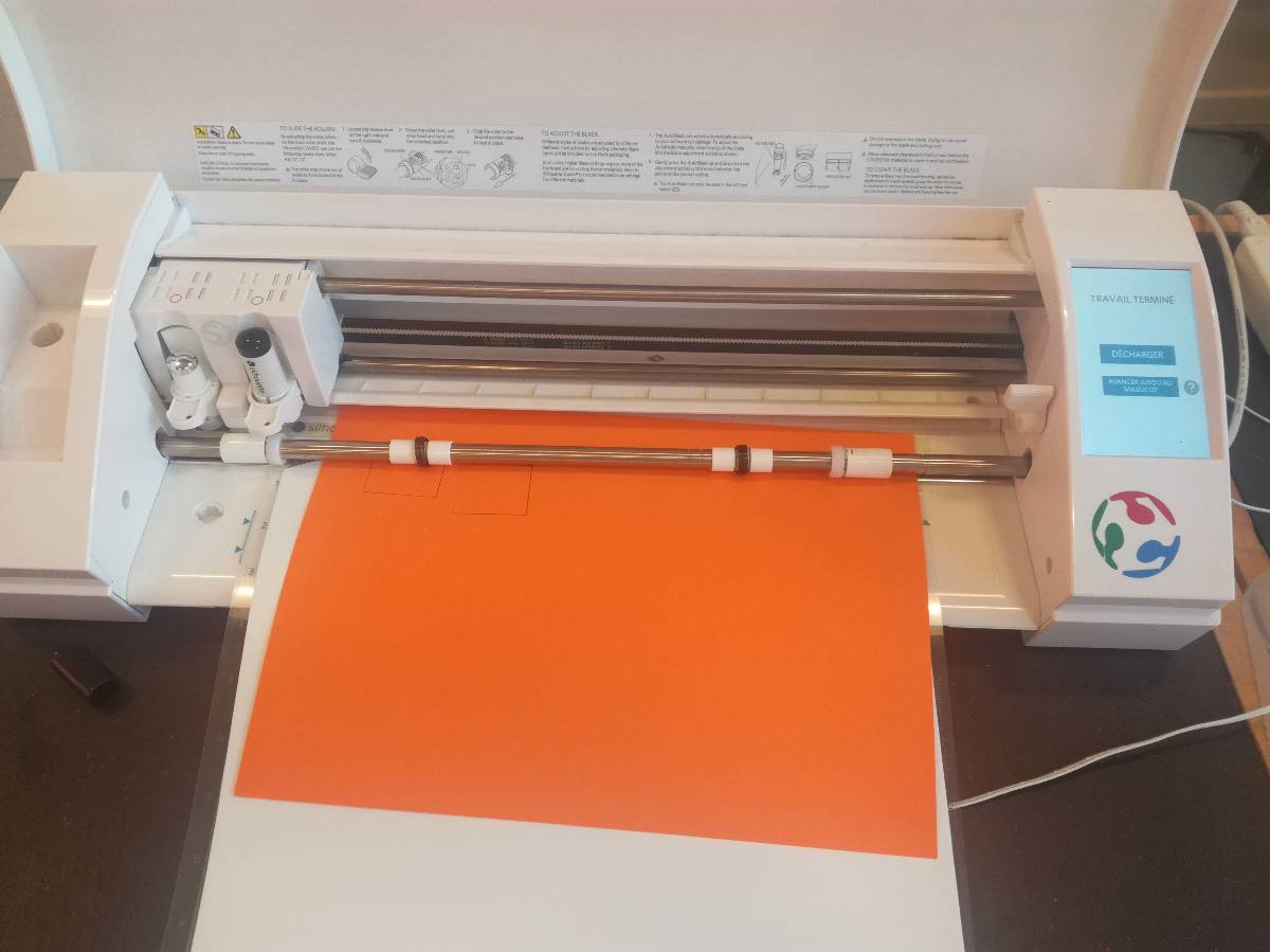
Here, I tested to cut with a blade and to draw using a pen as a second tool.

Then you start the cutting from the software.
You control up 3 main different parameters, the force, the speed and the depth of cut. I tested different combination and I got the right one.
To do that I cutted small squares using the vynil cutter on the vynil I intended to use for the mask and made some tests !
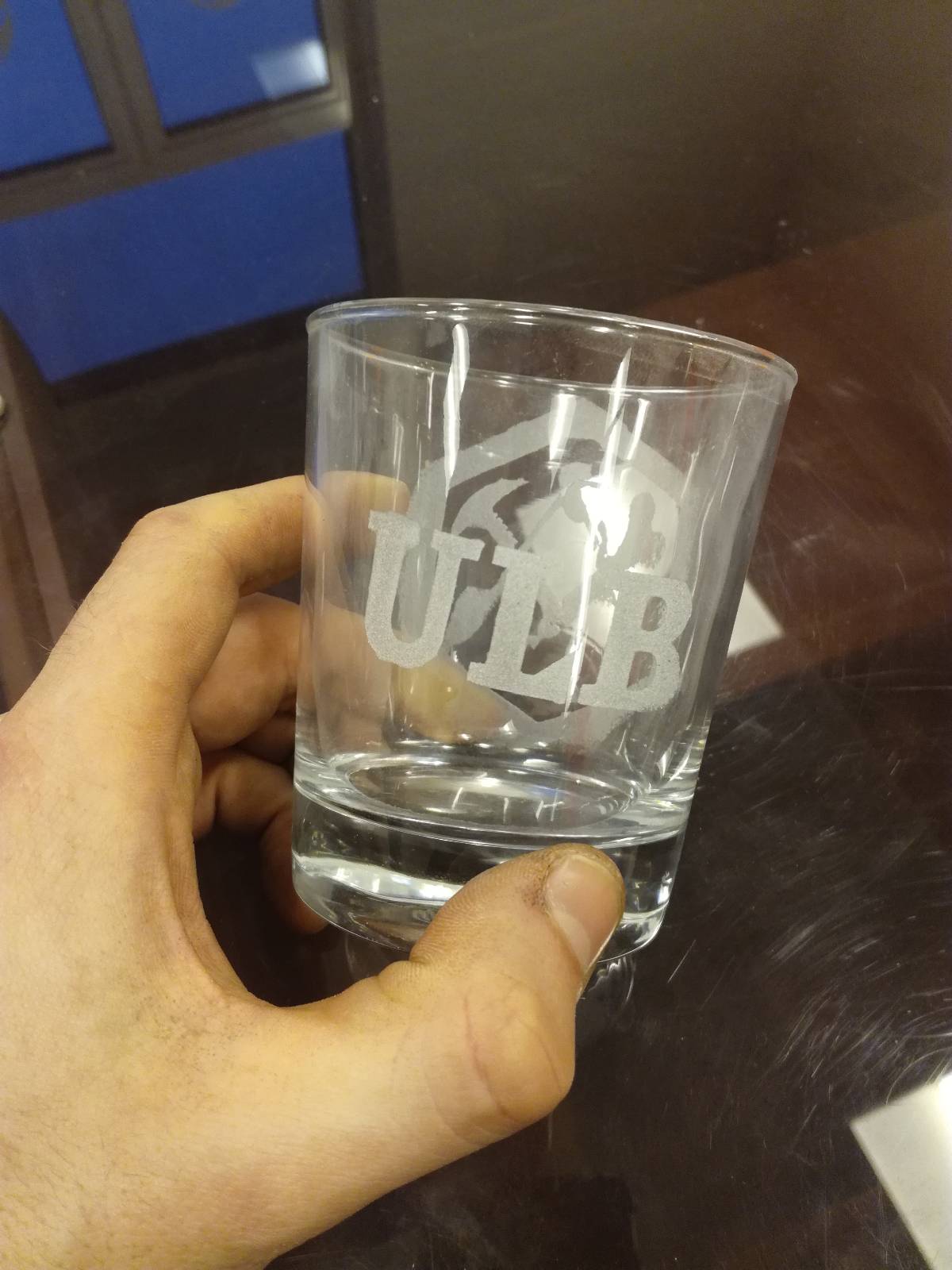
and the logo:

Regarding the file, I simply took the university logo in PNG and uploaded it in the Silhouette software and vectorised it there.
| To transfer the vynil I used some adhesive | |
|
|
I removed the adhesived and carefully took out the pieces of vynil that had to go |
|
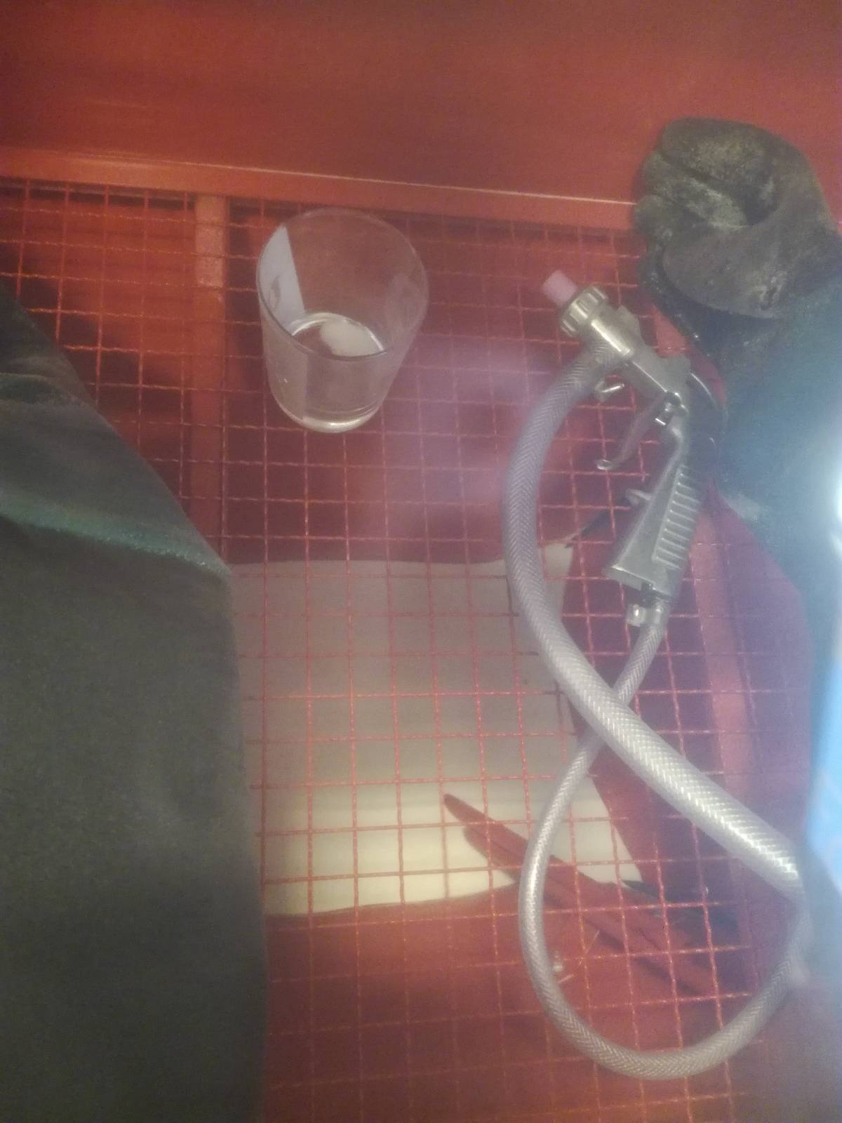
Let's go sandblasting, remember to start the aspirator, close the machine, plug the compressed air, open the valve and check the amount of sand in the machine. |
|
Here is the result ! |
Files
For parametric designs, you need an Onshape account (free) and then make a copy of the file:
- Construction kit CAD
- Lamp kit CAD
- Fruit Basket kit CAD
- Construction kit SVG
- Lamp kit SVG : make sure to cut 2 circles and 20 blades, I had to cut 3 planks to get the full kit.
- STL file of the Lamp Assembly
- ULB Vynil Logo
- Color calibration grid SVG