Group assignment
(Link)In this week group assignment, we will be sending message between two projects, I will be working with Abdallah AlSafadi his board will be the Master and my board will be the Secondary board.
It is communication between two Atmega 328 boards connected by these pin (SDA, SCL, GND, VCC)
Master board (Abdallah Al Safadi)
I used my Atmega 328 board as Master to send the signal to the Secondary board, using the following code:
          #include <Wire.h>
void setup()
{
  Wire.begin(); // join i2c bus
}

void loop()
{

  Wire.beginTransmission(1); // transmit to device #1
  Wire.write("a");// sends a to turn on LED at 500 ms intervals
  Wire.endTransmission(1); // stop transmitting
  delay(1000);

}
Secondary board (Ohood Walid)
I used my Atmega 328 board as Secondary board to receive letter “a” from Master board to Blink the LED as the command mention in the below code:
          #include <Wire.h>
void setup()
{
  Wire.begin(1);                // stablish an I2C connection on slave #1
  Wire.onReceive(receiveEvent); // register event
  Serial.begin(9600);           // start serial for output
  pinMode(5,OUTPUT);// sets LED as output
}
void loop()
{
  delay(10);
}
void receiveEvent()
{
  while(Wire.available()) // while the connection is availabe
  {
    char a = Wire.read(); // recieves the button state
    //Serial.println(c); // prints the button state on the serial monitor
  if (a =='a'){ // if the button is released
    digitalWrite(5,HIGH);// turn the LED off
    delay(1000);
    digitalWrite(5,LOW);// turn the LED off
  }
}
}
This video shows the successful communication between the boards.
Individual assignment
In this week we will learn how to integrating multiple processor in order to network & communicate between the boards. I will be using the PCBs that I designed in previous weeks. To understand this week assignment I visit this Website that give a summarized information. Which first give introduction about I2C protocol.
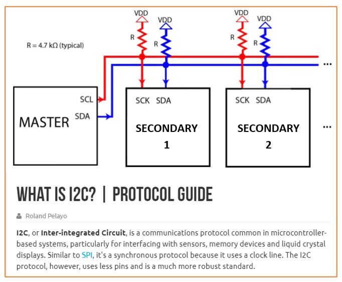
I2C protocol
The I2C protocol is employed to network Integrated Circuits & create communication between two or more ICs, therefore it's named as Inter-Integrated Circuit (I2C) communication. Also it could even be a communication protocol between two ICs that are located on the identical PCB.
Two paths that used by I2C to connect is SDA and SCL:
• SDA (Serial Data to send and receive data).
• SCL (Serial Clock the path that carries the clock signal).
Coding
In this week I worked on networking between ATMEGA328 and ATtiny44 using I2C protocol, where the master ATMEGA328 are attached with a pushbutton and then the signal are transferred to the secondary ATtiny44 to switch on the LED.
I connected the boards then I start following the instruction on this Website to write the code with doing some modification.
Master ATMEGA328
#include <Wire.h>

int x = 0;
int sensorPin = 7;
int sensorValue = 0;

void setup() {
// Start the I2C Bus as Master
 pinMode(sensorPin, INPUT_PULLUP);
Wire.begin();
Serial.begin(9600);

}

void loop() {

sensorValue = digitalRead(sensorPin);
Serial.println(sensorValue);
Wire.beginTransmission(1);

// transmit to device #1

Wire.write(sensorValue);

delay(100);

Wire.endTransmission();

// stop transmitting

}
Secondary ATtiny44
#include <Wire.h>

// Include the required Wire library for I2C

 int LED = 10;

 int x = 0;

 void setup() {

 // Define the LED pin as Output

 pinMode (LED, OUTPUT);

 // Start the I2C Bus as Slave on address 1
 Wire.begin(1);
 // Attach a function to trigger when something is received.
 Wire.onReceive(receiveEvent);
 //bit rate for data transfer over Serial communication
 Serial.begin(9600);

 }

 void receiveEvent(int bytes) {
 x = Wire.read(); // read one character from the I2C
 }

 void loop() {

 Serial.print("X is: ");
 Serial.println(x);

 if (x==0){

   digitalWrite(LED, LOW);
 }
 else

 {
  digitalWrite(10, HIGH);   // turn the LED on (HIGH is the voltage level)
  delay(1000);                       // wait for a second
  digitalWrite(10, LOW);    // turn the LED off by making the voltage LOW
  delay(1000);                       // wait for a second

 }
video of the successful communication