WEEK 4
1. Electronics Production
Group assignment: characterize the design rules for your PCB production process.
Individual assignment: make an in-circuit programmer by milling and stuffing the PCB, test it, then optionally try other PCB processes.
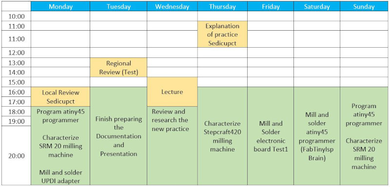
I have developed a weekly work plan that I describe in the following calendar.
1. Group assignment
Go to the Sedicupct website
2. Individual Assignment
2.1 Make an in-circuit programmer
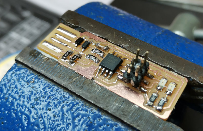
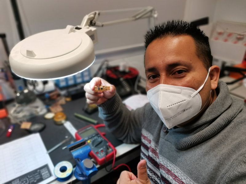
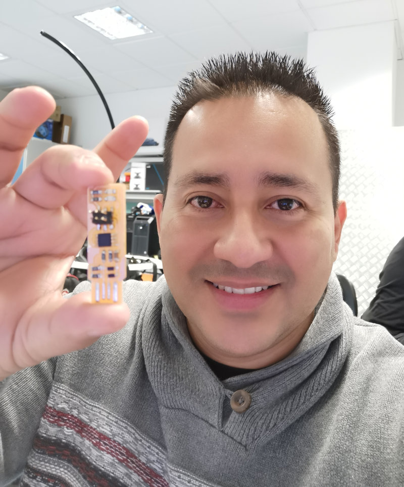
I made the FABTINYISP BRAIN programmer. I have followed the following tutorial.
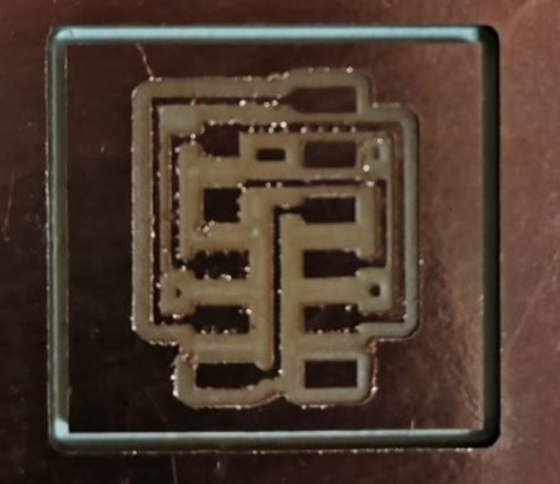
2.1.1 Milling
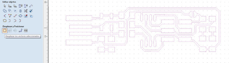
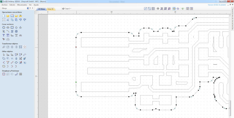
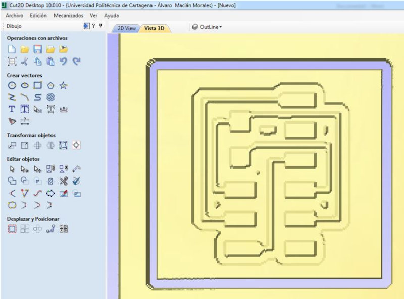
Use the Stepcraft420 milling machine. With the Cut2D program he generated the Gcode. I open Cut2D, created a new project, configured the material, imported the Bitmap for the contour tracing and Adapt the vectors to the bitmap. I ungroup all the vectors in the bitmap.
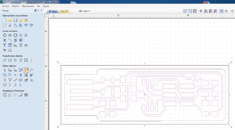
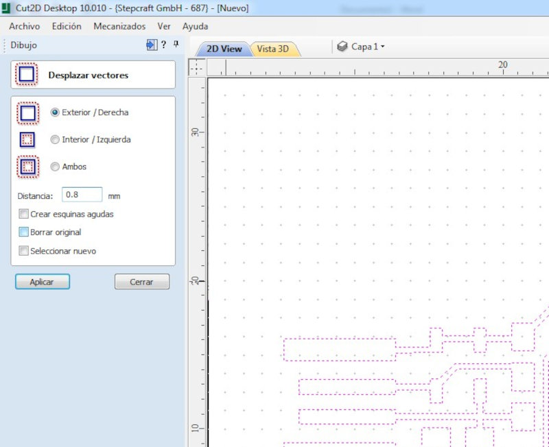
Offset selected vectors and Displace the vectors (Outside / Right) to a distance of 0.8mm.
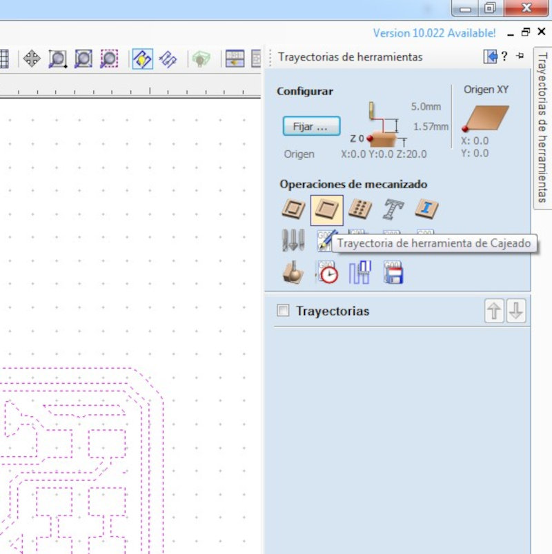
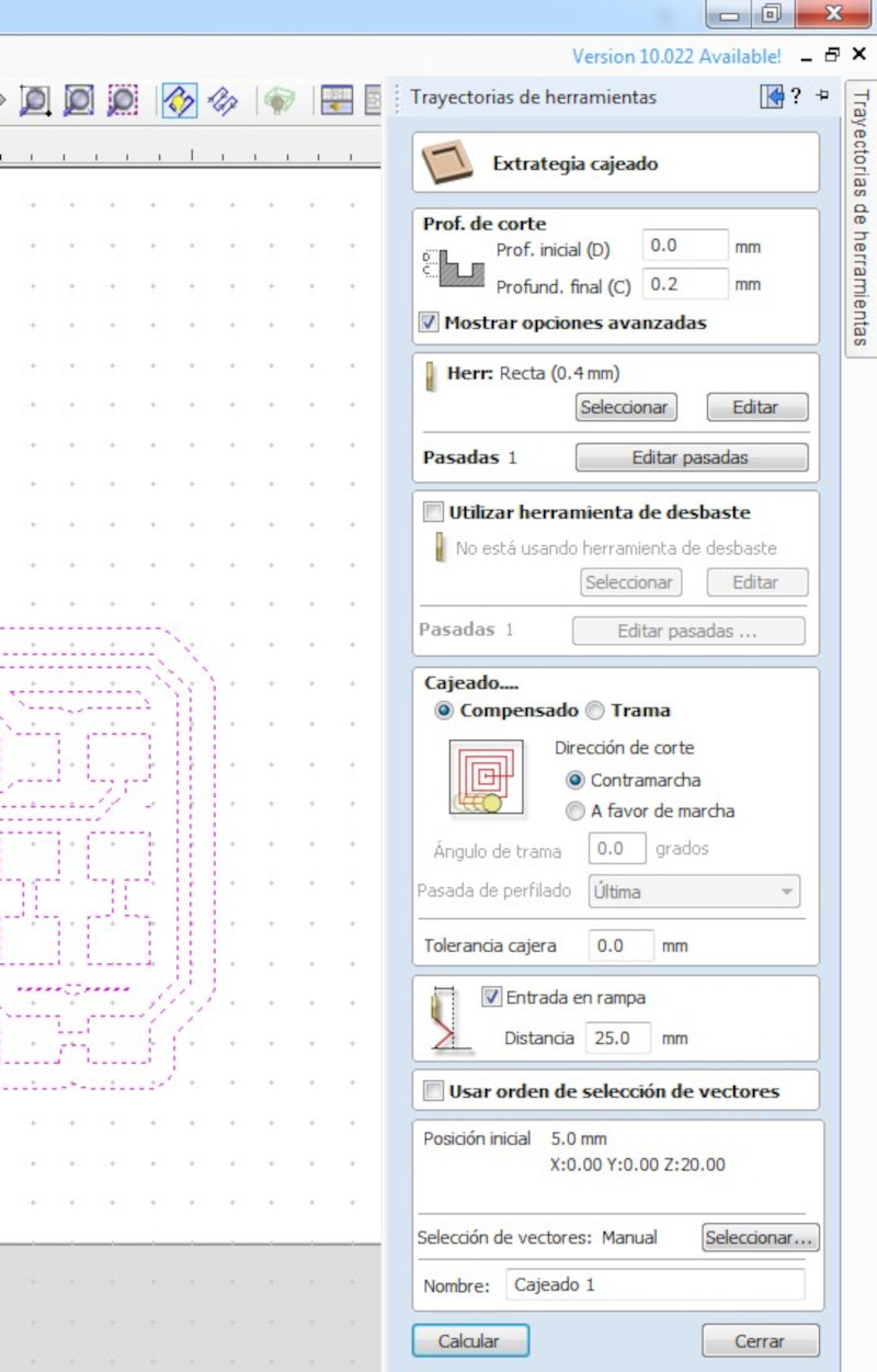
I configure in the tool path the machining operation "boxed tool path" use a 0.4mm (1/64") drill bit
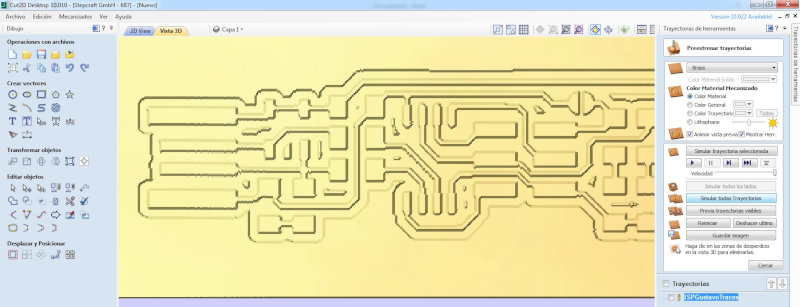
Simulate the boxed path.
Modify the outline of the vectors to avoid removing material with the cutter. I use D to remove nodes.
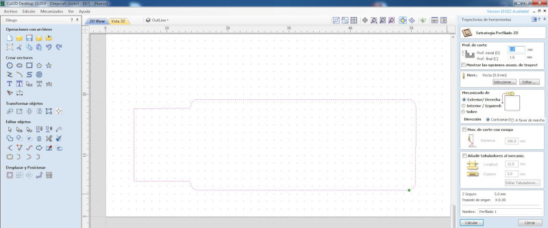
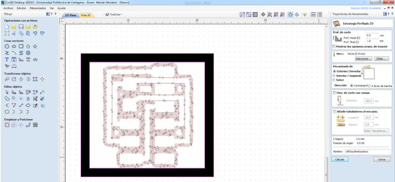
For the profiling machining operation “Profiling Toolpath” use a 0.8mm (1/32 ”) milling bit.
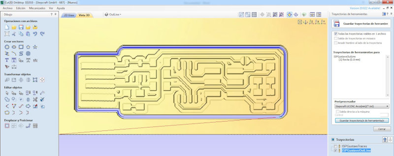
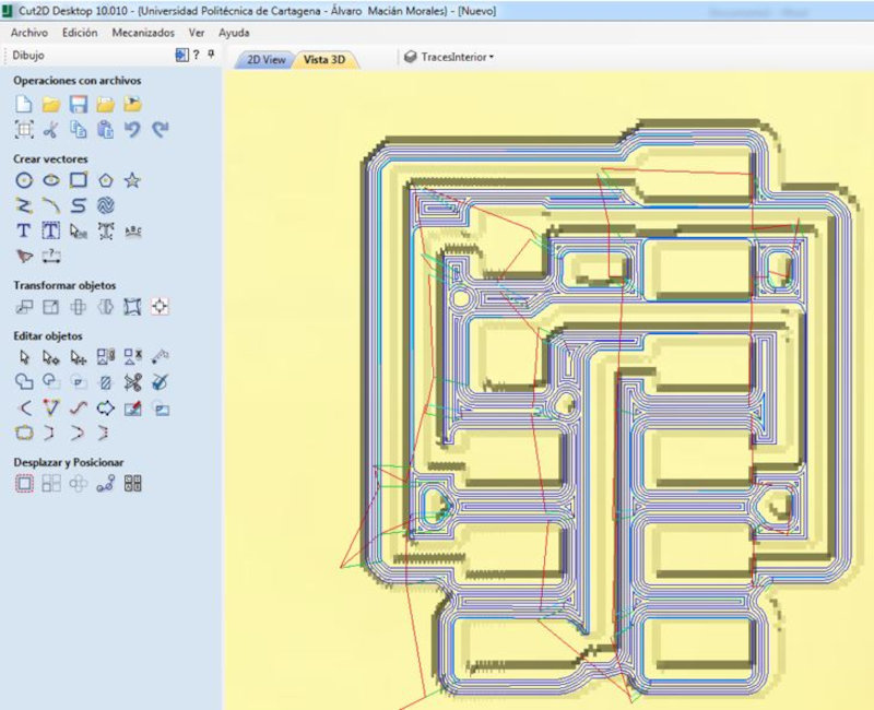
I simulate the trajectories of boxed and profiling. I keep the Gcode paths.
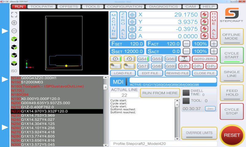
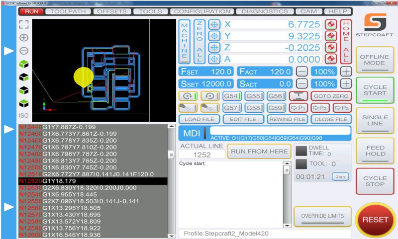
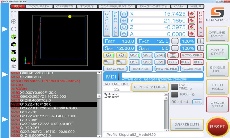
Open the UCCNC program to control the Stepcraft milling machine. Import the Gcode of the box in (Upload file). Place the 1/64" milling bit and place the x, y, z axes. Click (cycle start).
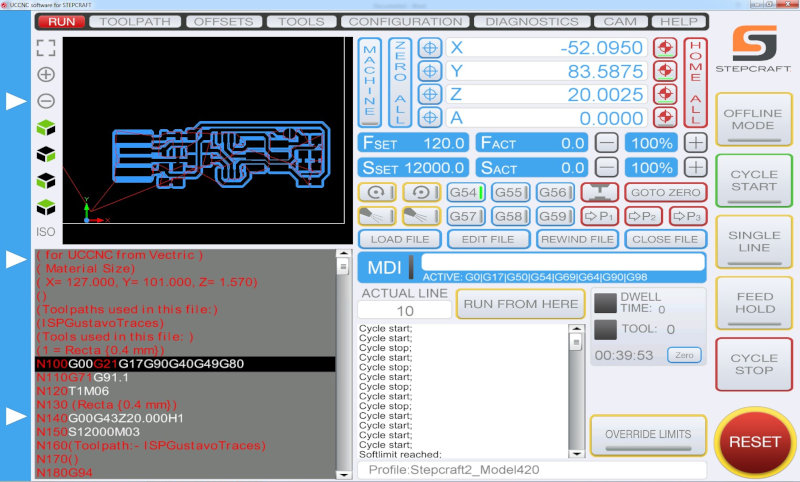
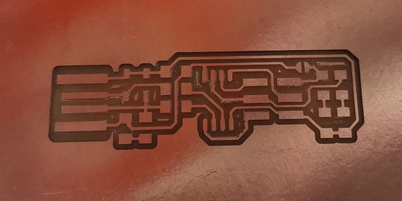
Import the Gcode of the profiling in (Upload file). Place the 1/32" milling bit and place the x, y, z axes. Click (cycle start).
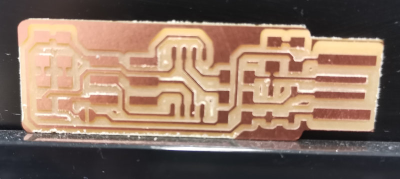
2.1.2 Solding
Use a template to identify the electronic components that I will use.
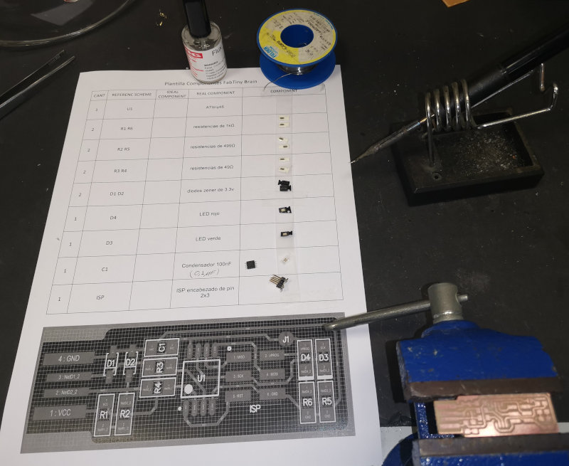
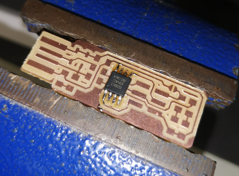
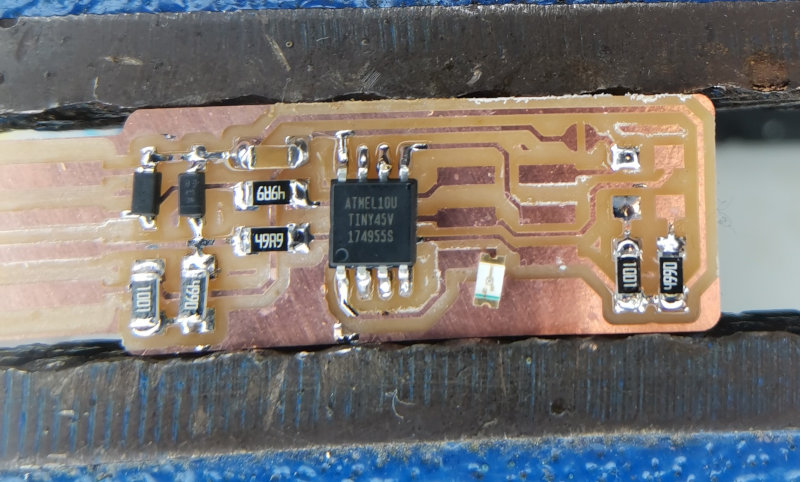
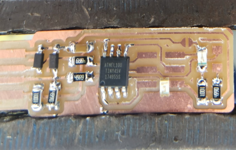
Initially solder the Atiny45, then the smaller components and finally the ISP.
2.1.3 Programming
I did the programming in Windows and followed the following tutorial.
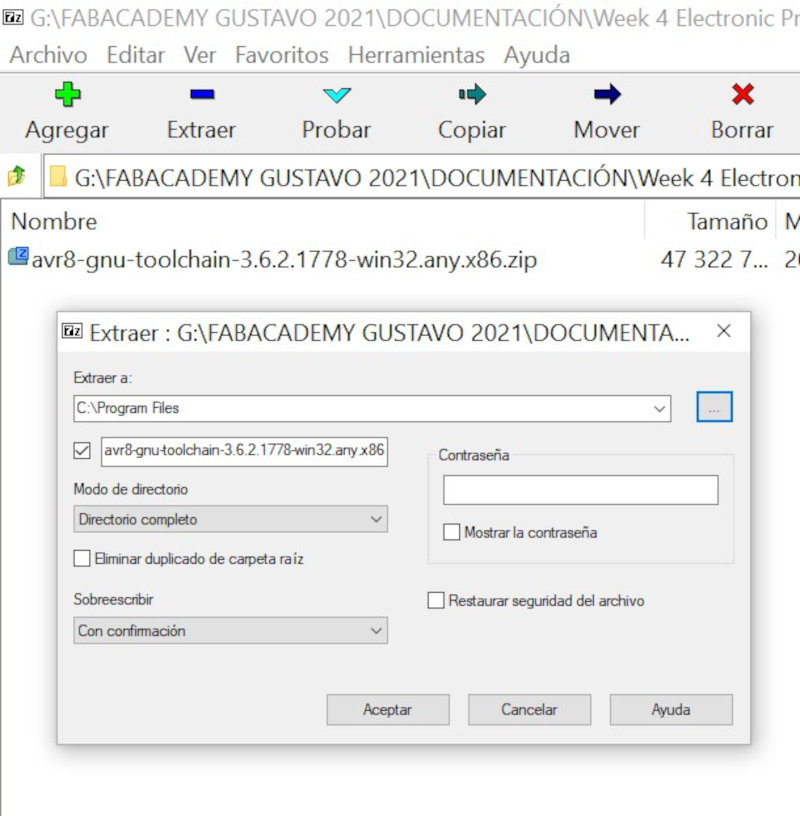
2.1.3.1 Dowloading Avr toolchain for Windows
Download and install the AVR Atmel GNU Toolchain. Atmel AVR Toolchain (AVR 8-bit Toolchain version v3.62 - Windows).
Unzip and extract into C: Program Files
2.1.3.2 Dowloading Avrdude
Download and install the Avrdude. Unzip the archive, and copy the archive inside to C:\Program Files.
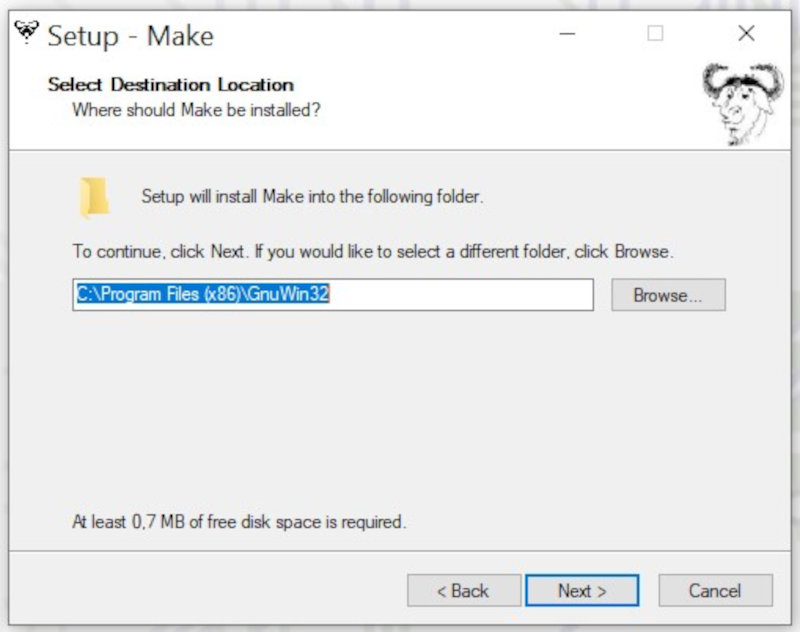
2.1.3.3 Download Gnu Make
Download Gnu Make Unzip the archive, and copy the archive inside to C:\Program Files(x86).
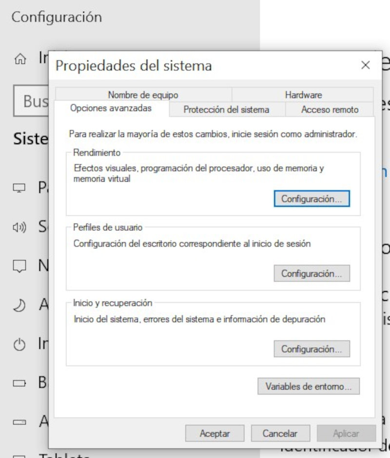
Update path in (System Properties - Advanced Options - Environment Variables). Enter Path and modify "edit"
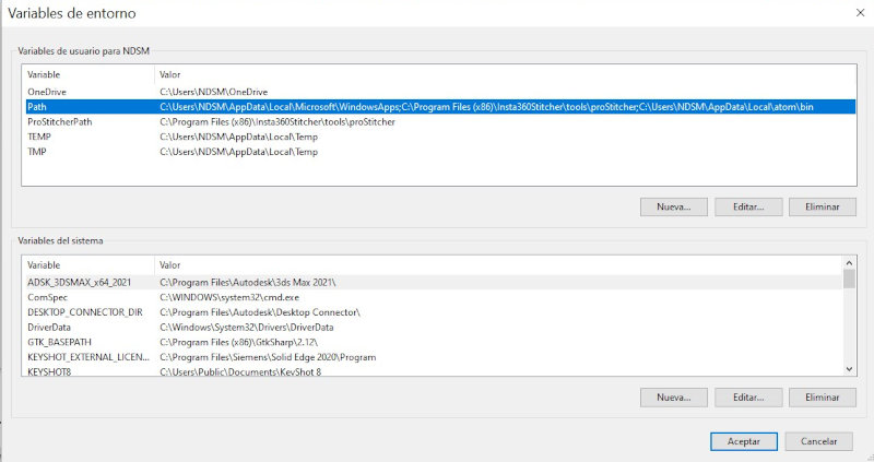
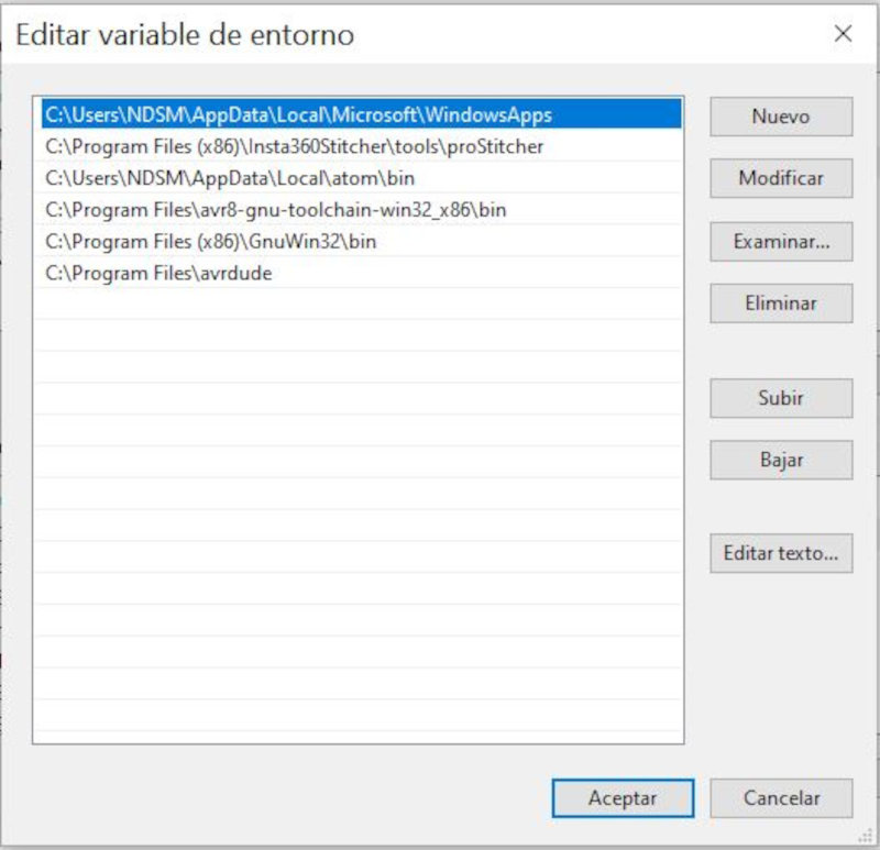
Enter new environment variables (New). The three values to add are: (C: \ Program Files \ avr8-gnu-toolchain \ bin) (C: \ Program Files (x86) \ GnuWin32 \ bin) (C: \ Program Files \ avrdude).
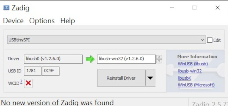
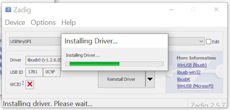
2.1.3.4 Download and install Zadig
Download Zadig 2.5.
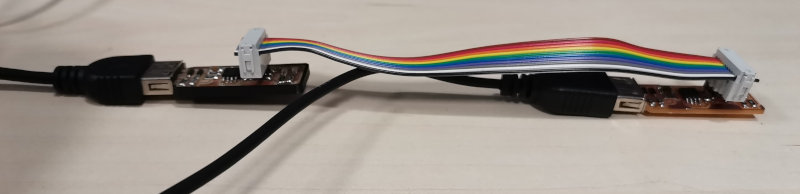
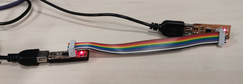
I connected a programmer that Alvaro and Lola left me to the usb port of the computer and through an ISP connector I connected my programmer to the programmer. In addition, you must feed the new programmer through its usb port to another external power supply.
Open Zading and select Options "List all devices". Select Drive (libusb0 (v.12.6.0) and (libusb-win32 (v1.2.6.0). Click Reinstall Driver
2.1.3.5 Git Bash
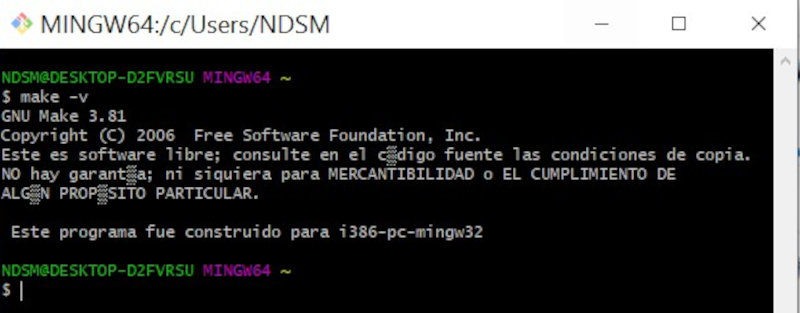
Open Git Bash and write the following codes:
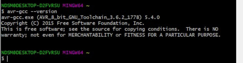
make -v
avr-gcc --version
avrdude -c usbtiny -p t45
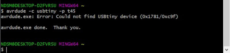
I got an error message (avrdud.exe: Error: Could not find USBtiny device (0x1781 / 0xc9f). I have reviewed the previous steps and everything is correct. I don't know what is wrong, but I will continue with the following steps.
2.1.3.6 Install Firmware
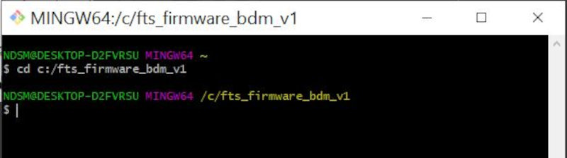
Download the firmware (file) and unzip it. In Git Bash look for the folder where the firmware is unzipped. Write the following commands
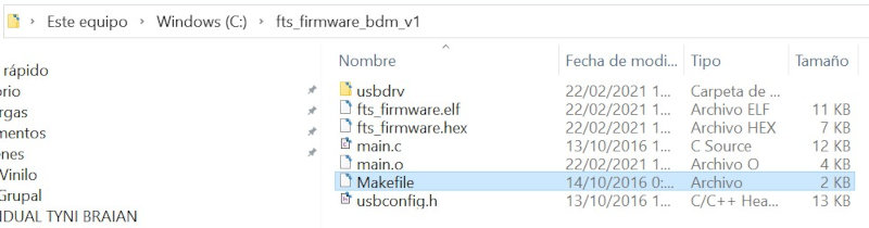
cd fts_firmware_bdm_v1
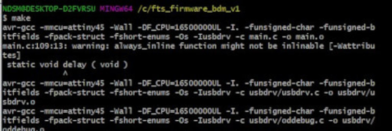
make
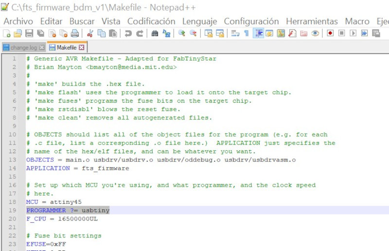
Open the Makefile file. You need a text editor like notepad++.
Open the Makefile file with Notepad ++. Check in the code: (MCU = attiny45) (PROGRAMMER? = Usbtiny).
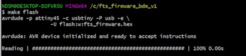
In Git Bash Do (make flash).
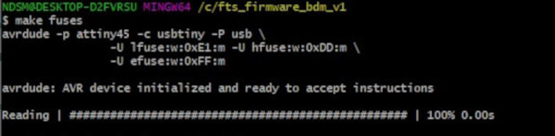
make fuses
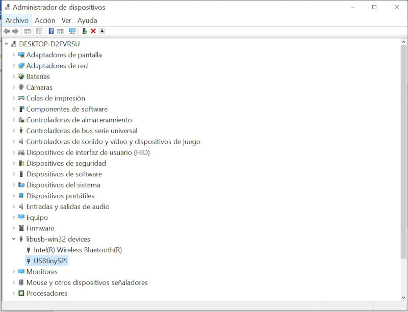
Disconnect the programmer and connect only my new programmer and see in device manager if the USBtinySPI appears.
Reconnect the programmer with my programmer.
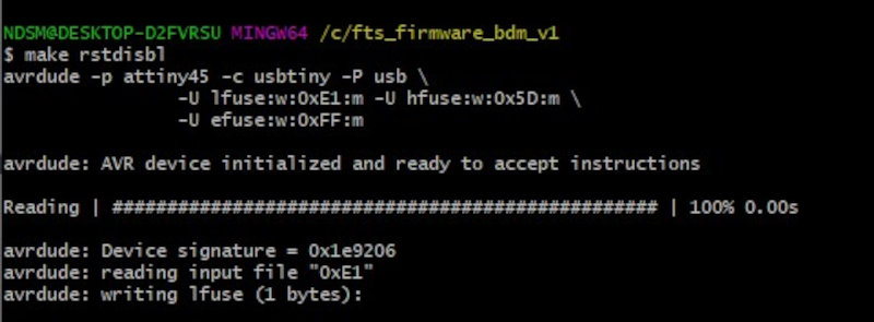
Enter Git Bash and write the code (make rstdisbl).
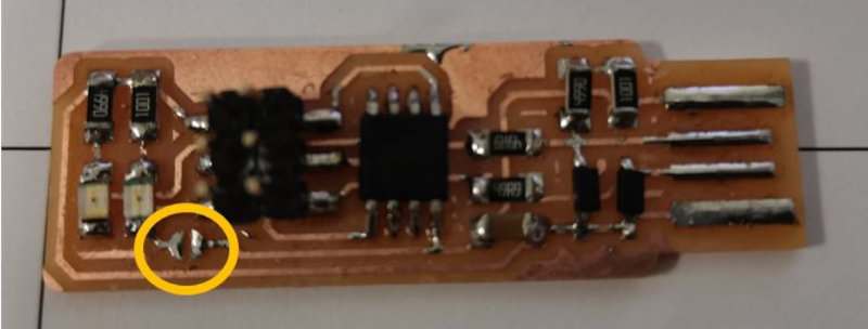
Desolder the Vprogram pin on my programmer.
It has finally worked.
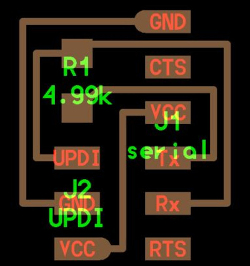
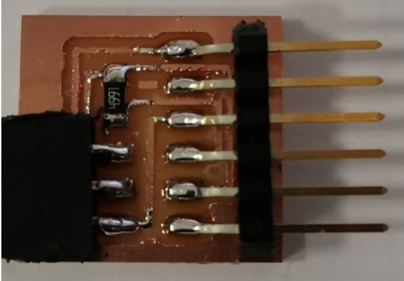
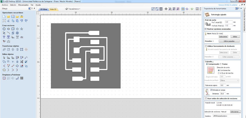
3. UPDI adapter
I am going to mill and solder a UPDI adapter, in later projects I will design electronic boards that are programmed through the UPDI connection. This "UPDI adapter" board has at one end the connection (UPDI, GND and VCC) that connects to the board with pins of the same configuration. At the other end are the FTDI connection pins, which will be connected to an FTDI / USB adapter cable that will be connected to the USB port of the Computer.
Open Cut2D and import the bitmaps and configure the slotting strategy.
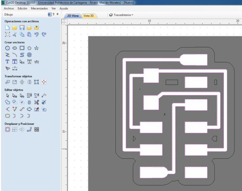
Import the bitmap and configure the profiling path. Save the paths as Gcode files.
Open UCCNC and load the Gcode file of the pocket and place a 0.4mm drill bit in the router.
Load the Gcode file of the profiling and put a 0.8mm drill bit in the router.
Solder the electronic components.