Concept
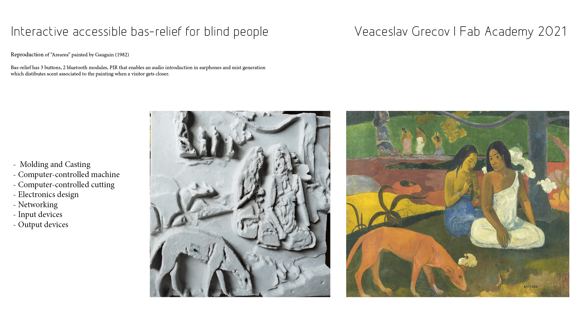
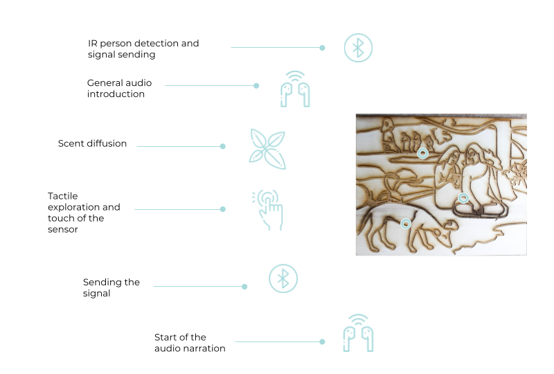
Final Project consists in the continuation of my thesis research on cultural accessibility for blind people in museums. The solution implemented consists in a bas-relief of a painting that has sensors and buttons that enable audio reproduction. When a blind person gets closer to the artwork, they receive a general audio introduction in the earphones and can smell the scent associated to the painting. In the moment when the visitor touches a particular area of representation and pushes a button, an audio explanation is transmitted to the earphones.
Intro
Globally, approximately 36.0 million of people are blind, 216.0 million have a visual impairment ranging from moderate to severe, and 188.5 million have a mild visual impairment (Bourne et al., 2017). A more recent report indicates that at least 2.2 billion people have a visual impairment, and of those, at least 1 billion have a visual impairment that could have been prevented or has yet to be addressed (WHO, 2019). Despite the very high frequency of visual impairements and their entrenchment over time, society is not particularly adapting to the situation, creating significant inconveniences in the ordinary lives of thousands of people.
Even though some efforts have been already made to increase accessibility for people with disabilities and the growing concern about this topic, many people with a visual impairment still experience several limitations in their daily lives and only 5.5% of blind and visually impaired people visit museums in Europe .
Design Thinking
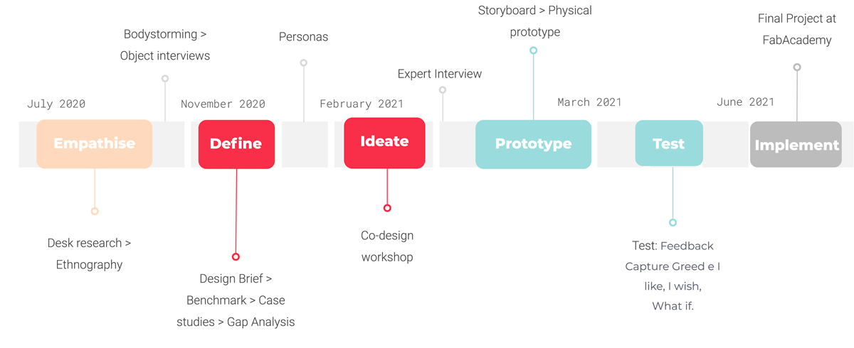
I have followed the human-centred process and mindset of Design thinking that permits to explore and find out the needs and desires of final users, simultaneously testing the design assumptions and solutions with them. In the image below you can see all the methods used during my research:
Prototype & Test
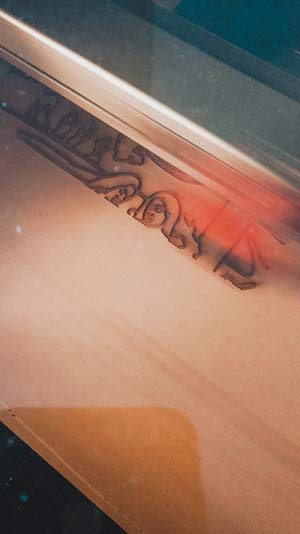
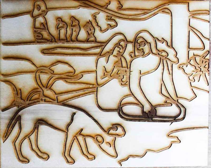
I would focus directly on this phase of my thesis as it impacted project development at Fab Academy and was actually a part of it. In order to test my final solution with blind people, I needed a prototype of it. I was mostly interested in evaluating the interaction and the main concept, rather than the representation itself. Also because to have a representation of the painting I would need to create a bas-relief. During the first weeks of Fab Academy I learned how to use laser cutting machine, so I decided to create an ingraved relief on wood, where I would make smell the scent, turn on the audio files through bluetooth earphones when blind person touches associated elements.
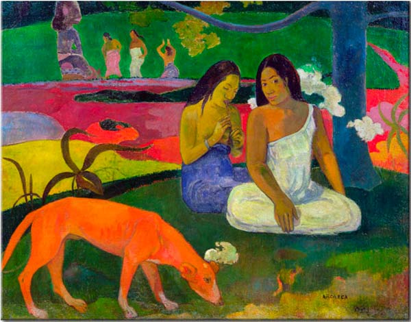
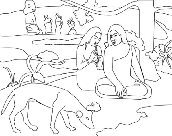
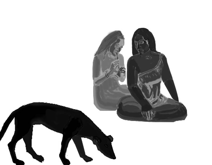
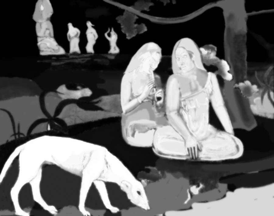
I used a vector image of the painting "Arearea" (1892) by Gauguin enlarging the traces because otherwise tactile exploration would be completely useless.
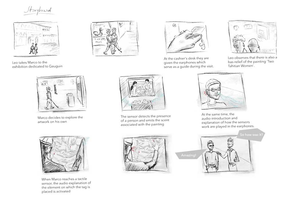
Here below a brief explanation of general functioning and a storyboard I created.
Bluetooth communication
As continuation of bluetooth experiments during networking week, I wrote a code where data would transmit between two HM-10 bluetooth modules: pressing a button connected to one Arduino the led would turn on another on. The issues regarded serial baud rates, cause they must be 115200 for Arduino and 9600 for bluetooth modules, it was necessary to switch TX and RX. Plus when I wrote first sketches of code I would get a very long delay of led switching on. Sometimes there would pass circa 2 minutes from the moment when I pressed the button and the led would light on, this was due to the delays of 1 second that I left, but also because I wrote a code where on serial monitor would appear 0 when the button is not pressed. For this reason, it would occupy the whole "queue" of communication and the real action of pressed button would come much later.
Slave's code that transmitted data:
  #include <SoftwareSerial.h>

#define button 2
int buttonState = 0;
SoftwareSerial bluetooth(11, 10); //RX, TX;

void setup() {
pinMode(button, INPUT);
Serial.begin(115200);
bluetooth.begin(9600);
delay(100);

}

void loop() {

   buttonState = digitalRead(button);

  if (buttonState == HIGH) {
    bluetooth.write("1");
    Serial.println("Button is ON");

  }
else
{
   bluetooth.write("0");
   Serial.println("Button is OFF");

}
delay(1000);
}
Master's code that receives data and turns on the Led:
  #include <SoftwareSerial.h>


#define ledPin 2
int state = 0;
SoftwareSerial bluetooth(11, 10);

void setup() {
  pinMode(ledPin, OUTPUT);
  digitalWrite(ledPin, LOW);
  Serial.begin(115200);
  bluetooth.begin(9600);

}

void loop() {
  if(bluetooth.available() > 0) {
    state = bluetooth.read();
  }
  if (state == '1') {
    digitalWrite(ledPin, HIGH);


  }
  else if (state == '0') {
    digitalWrite(ledPin, LOW);

  }
}
Afterwards following the suggestion of my instructor I wrote the code with three buttons where each button transmitted a number to another bluetooth module. This is because it's basically what I need for my final project: when a visitor presses a button, the latter sends a number to the wearable bluetooth module which receiving a specific number, enables audio explanation in the earphones. This time I did not put the numbers between the quotation marks writing the code: instead of bluetooth.write('2'); I left it as bluetooth.write(2);, in this way the second module does not interpretate these data in ASCII and just writes directly the number sent.
Slave's code with three buttons:
  #include <SoftwareSerial.h>

#define button1 2
#define button2 3
#define button3 4
int buttonState = 0;
SoftwareSerial bluetooth(11, 10);

void setup() {
  pinMode(button1,INPUT);
  pinMode(button2,INPUT);
  pinMode(button3,INPUT);
Serial.begin(115200);
bluetooth.begin(9600);
delay(100);

}

void loop() {

//Button 1//

  if (digitalRead(button1) == HIGH) {
    bluetooth.write(1);

    Serial.println("Button is 1");
      delay(100);
      }
      else
{

   Serial.println("Button is OFF");
     delay(100);

}


//Button 2//

  if (digitalRead(button2) == HIGH) {
    bluetooth.write(2);

    Serial.println("Button is 2");
      delay(100);
      }


else
{

   Serial.println("Button is OFF");
     delay(200);

}

//Button 3//

  if (digitalRead(button3) == HIGH) {
    bluetooth.write(3);

    Serial.println("Button is 3");
      delay(100);
      }

 else
{

   Serial.println("Button is OFF");
     delay(100);

}

}
Master's code that prints on serial monitor number received:
    #include <SoftwareSerial.h>

#define ledPin 2
int state = 0;
SoftwareSerial bluetooth(11, 10);

void setup() {
 pinMode(ledPin, OUTPUT);
 digitalWrite(ledPin, LOW);
 Serial.begin(115200);
 bluetooth.begin(9600);

}

void loop() {
 if(bluetooth.available()) {
   Serial.println(bluetooth.read());

 }
 delay(1000);
}
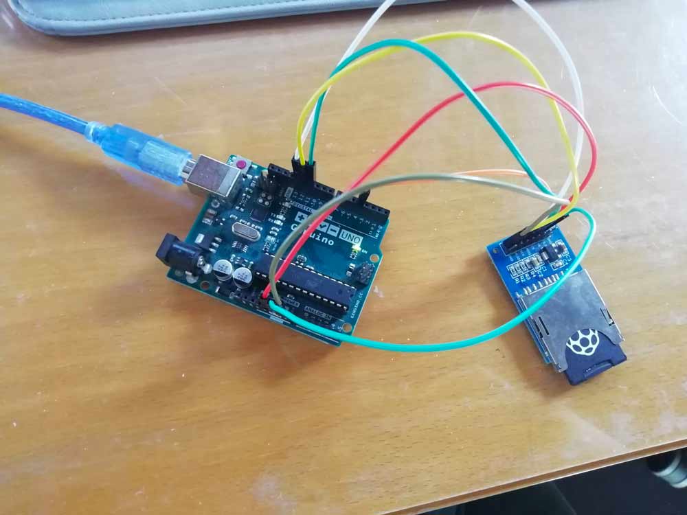
SD card
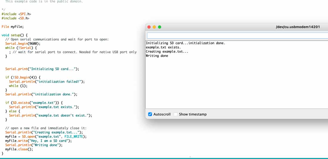
Since Arduino does not provide enough flash memory to contain audio files, I needed to try the code for SD card. I used the one below that checks if there is a text file on the card, if there is none it creates one with text in it. I followed this tutorial.
  #include <SPI.h>
  #include <SD.h>

  File myFile;

  void setup() {
    // Open serial communications and wait for port to open:
    Serial.begin(9600);
    while (!Serial) {
      ; // wait for serial port to connect. Needed for native USB port only
    }


    Serial.print("Initializing SD card...");

    if (!SD.begin(4)) {
      Serial.println("initialization failed!");
      while (1);
    }
    Serial.println("initialization done.");

    if (SD.exists("example.txt")) {
      Serial.println("example.txt exists.");
    } else {
      Serial.println("example.txt doesn't exist.");
    }

    // open a new file and immediately close it:
    Serial.println("Creating example.txt...");
    myFile = SD.open("example.txt", FILE_WRITE);
    myFile.write("Hey, I am a SD card");
    Serial.println("Writing done");
    myFile.close();
  }

  void loop() {
  }
Bas-relief
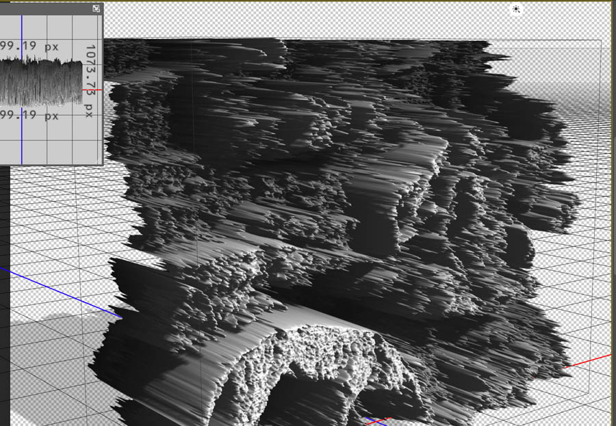
The biggest challenge was the question: how to transform a bidimensional image into threedimensional model? After some research I found Image2Surface add-in. I followed the general instructions from github in order to install it. The image to insert must be a grayscale depth map where black is the closest surface to the viewer and white the farest. So I made some trial images on using Photoshop. Although, the result was not satisfying, I had little control on modifications and when uploading the whole picture both mine and Lab's computers would take too much time to process.
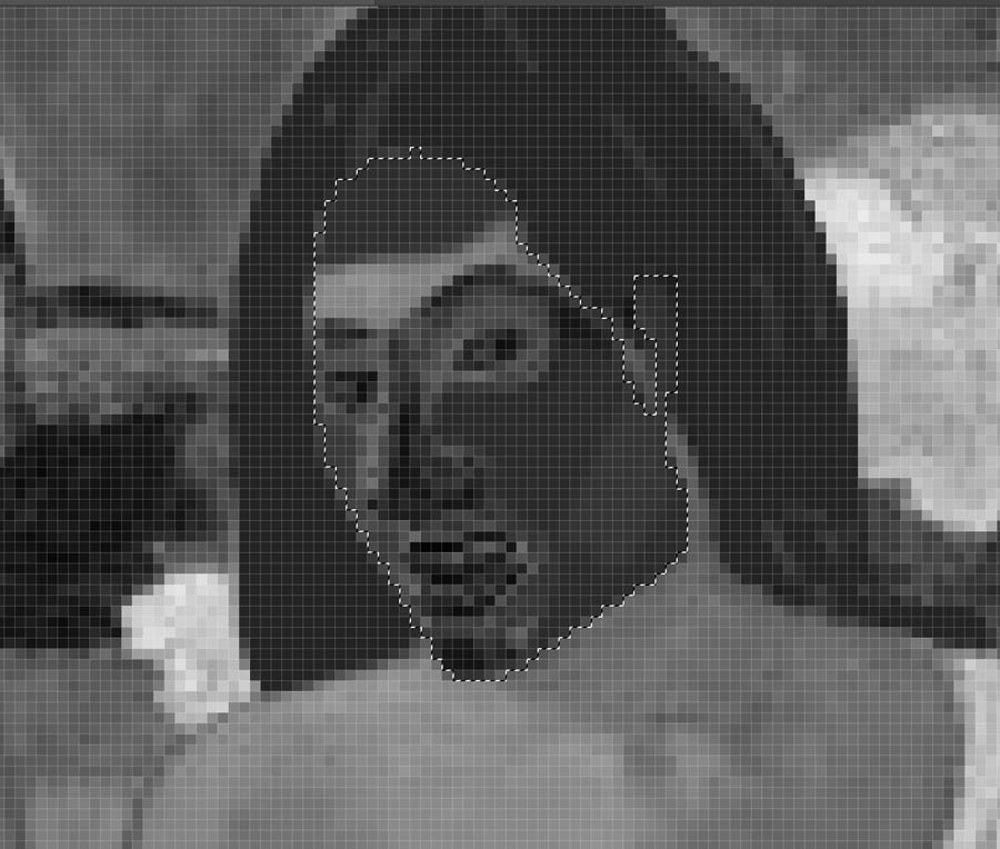
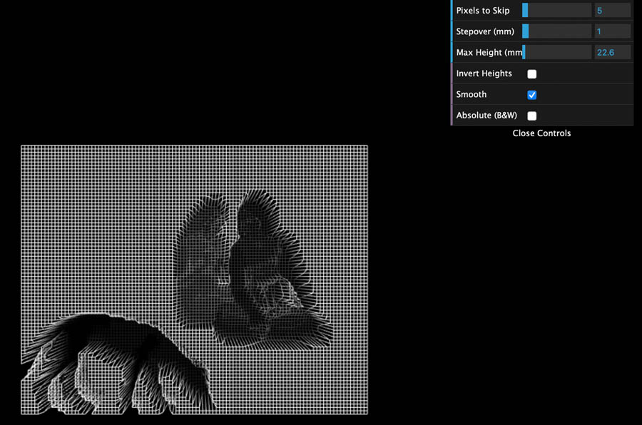
Browsing on the web I found two amazing tutorials that helped me to prepare the file and to create a 3D model on Blender. This time the process would be on reverse: white parts are the closest and the darkest are the farest. The issue is that Gauguin's painting is not a real representation, so in photoshop on chanells panel I chose red chanell as it offered the strongest contrast and started coloring by hand augmenting brightness and or darkness of parts that must be closer of futher from the visitor.
The first tutorial on the preparation of the file permits to transform an image into displacement map. I opened a picture of "Arearea" Gauguin's painting and kept red channel as I did for Image2Surface. Then I adjusted brightness of the parts that must be closer (higher in relief) for visitor using mainly lasso tool. After I went to Filter > 3D > Generate Bump Map > Object > Cube . The settings were for blur 11,1 and for detale scale 76%.
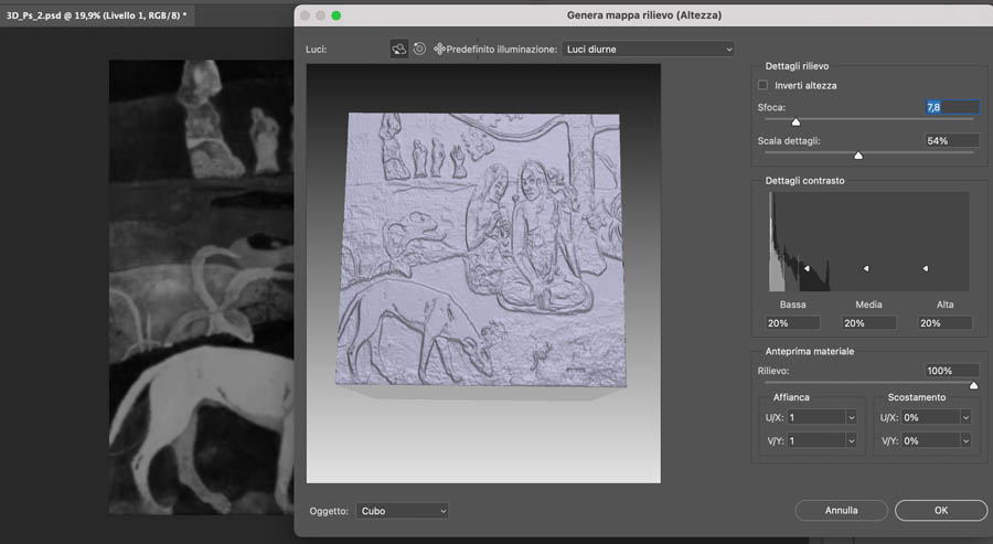
Then I copied the image from red chanell above the one just obtained and blured it with gaussian blur 3% as type of overlay of this level I used hard light. Then I came back to 3D, checked that it was mesh from depth map and pushed create. The previes that offers photoshop of 3D model is below.
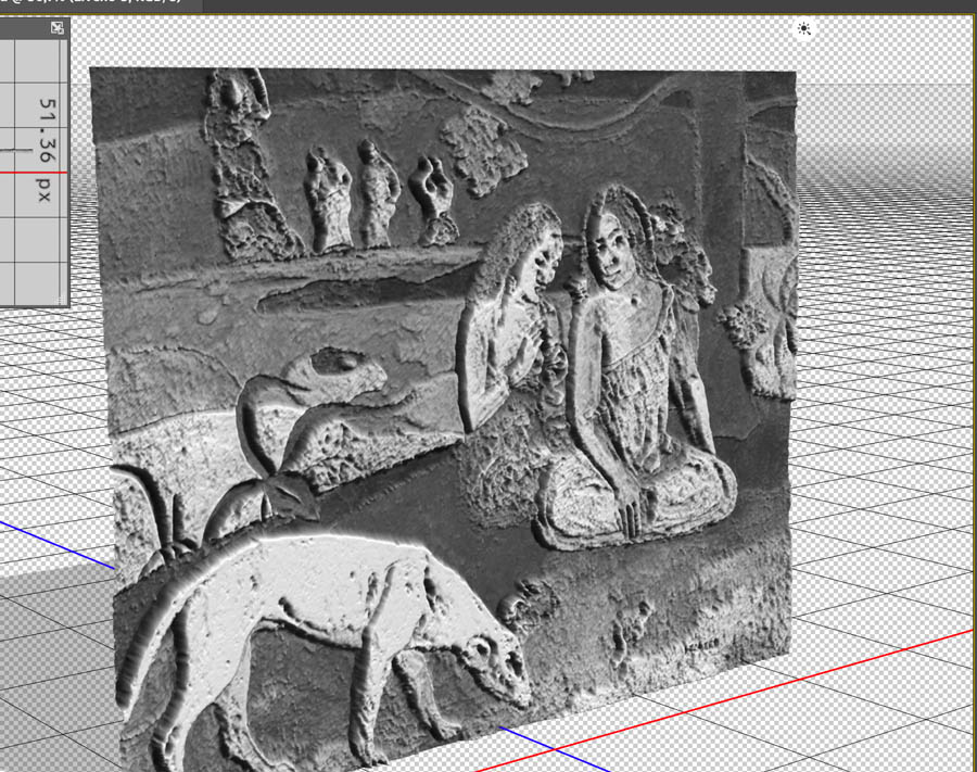
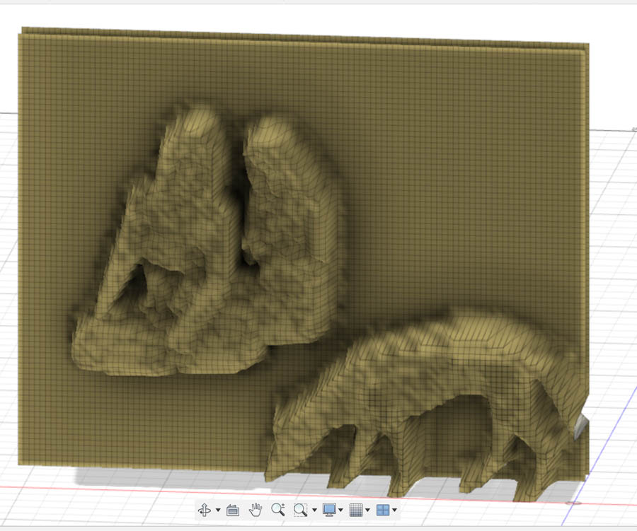
Following the tutorial for Blender I tried all 3 methods describes and as seen in the colored version of 3D model below, the result is not the best.
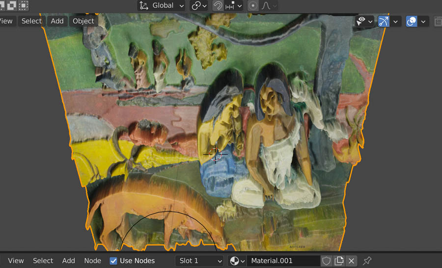
So I preferred the second method when going from Grid > Add Modifier > Subdivision surface > Simple > Render 4 > Viewport 4 then again Add Modifier > Displace > Add > Texture then go to Texture settings and add an image containing displacement map in grayscale. Then Object > Shade smooth, afterwards on modifier properties adjust Viewport and strenght.
Then a mold from this model was created since I needed to cast it with hydro-stone.
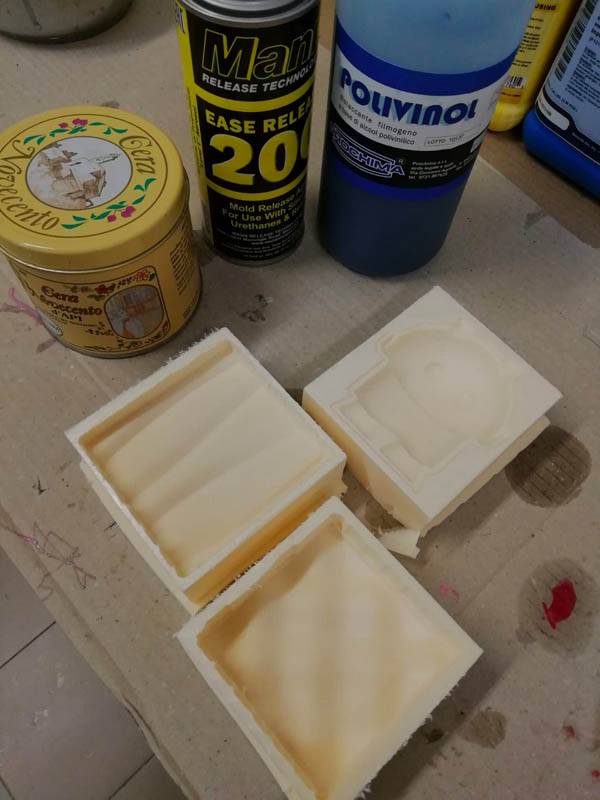
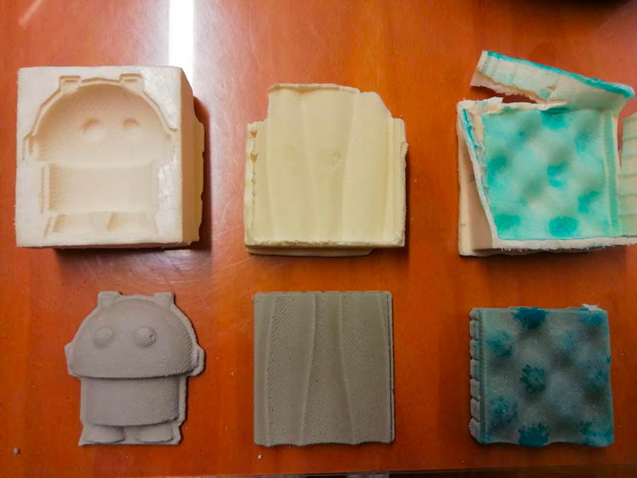
Molding and casting
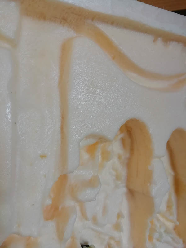
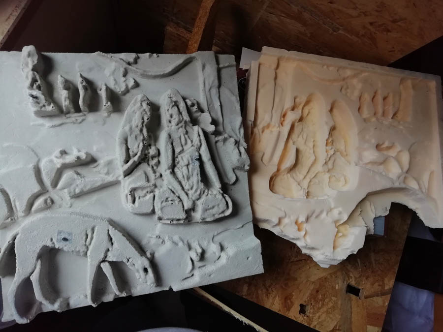
For casting I needed to study a type of release agent that would fit best for the future usage with Hydrostone. This is why in one of the forms I put beeswax, in another Ease Release™ 200 produced by Smooth-on and in the last polivinol. The latest I put at least 4 times waiting a couple of hours to make it dry. As seen in the image, the best result I obtained with beeswax, I did not even need to break the cast, whilst with release agent of smooth-on it got completely sticked to the surface of polisterol. Polivinol was something in the middle but left on the surface of the mold blue stains.
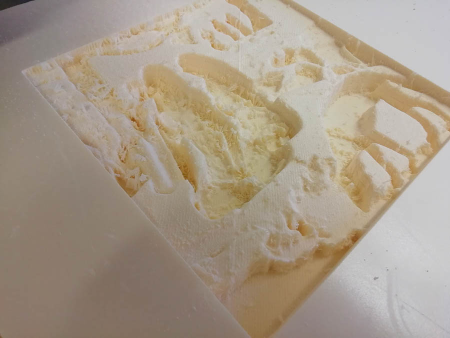
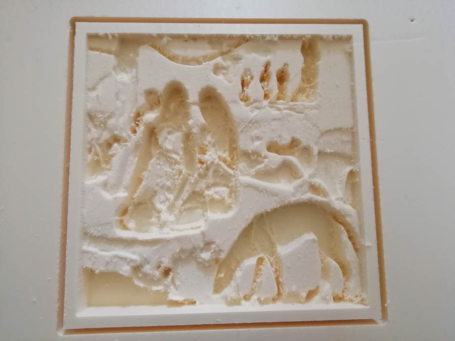
In the first picture below is the result after 10h of milling with ShopBot that got paused at the half of finishing and in the second the final result.
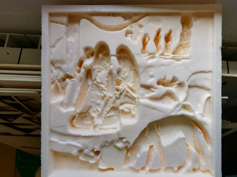
I took off all extra material and used a heat gun at 120 degrees to make the surface more smooth.
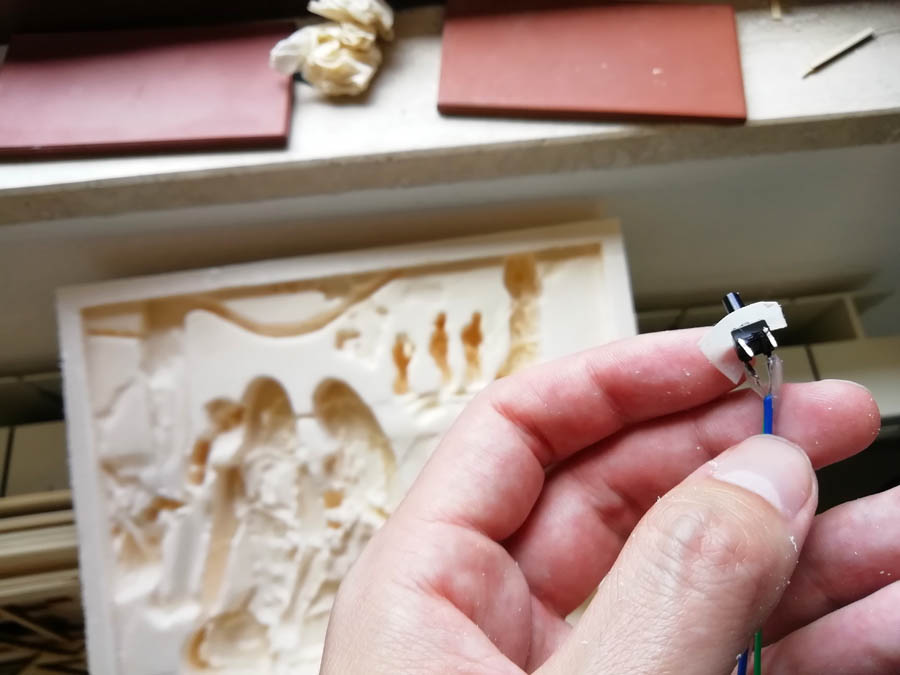
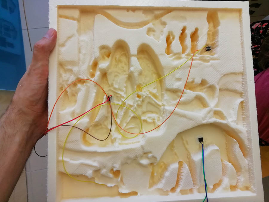
I needed to place high bottons that when pressed would enable audio narration in earphones of visitors. So decided to solder them with long wires and put in directly in the polisterol with a bit of scotch tape in order to prevent leak of hydrostone.
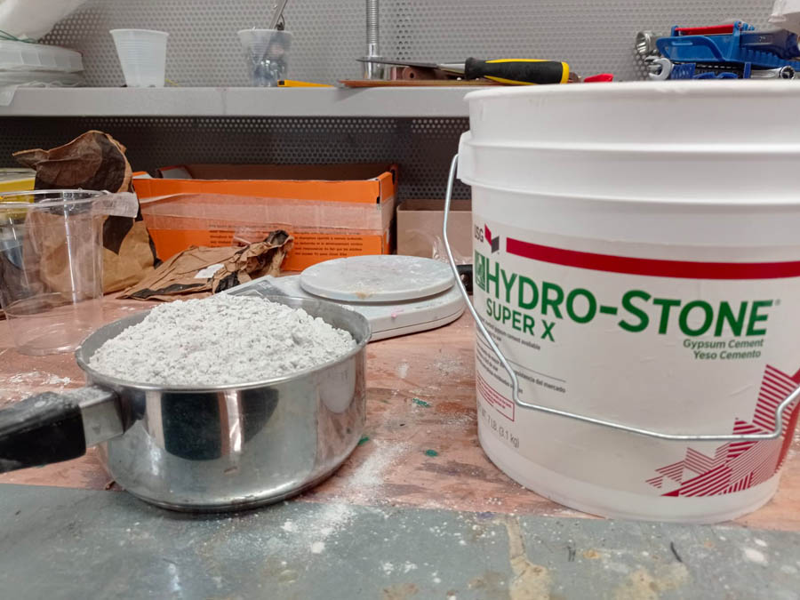
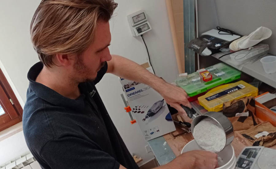
I applied beeswax on the surface as release agent and then mixed hydrostone, overall I used 3kg of the material and it took 18 hours to dry out.
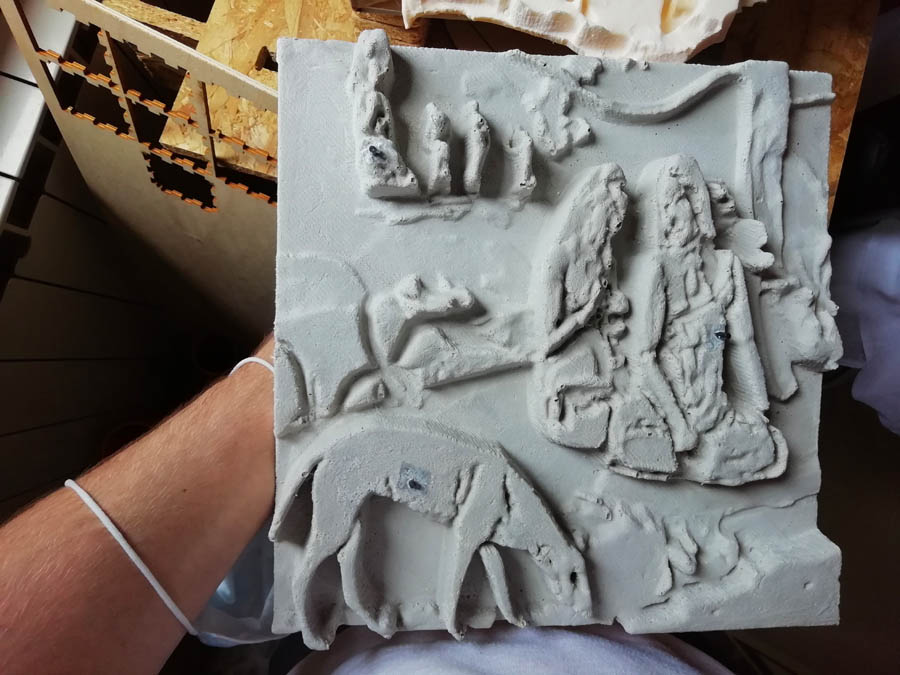
The bas-relief was quite easy to take out, but anyway I preferred to break the cast for major safety. Regardless, some bubble the result was quite satisfying.
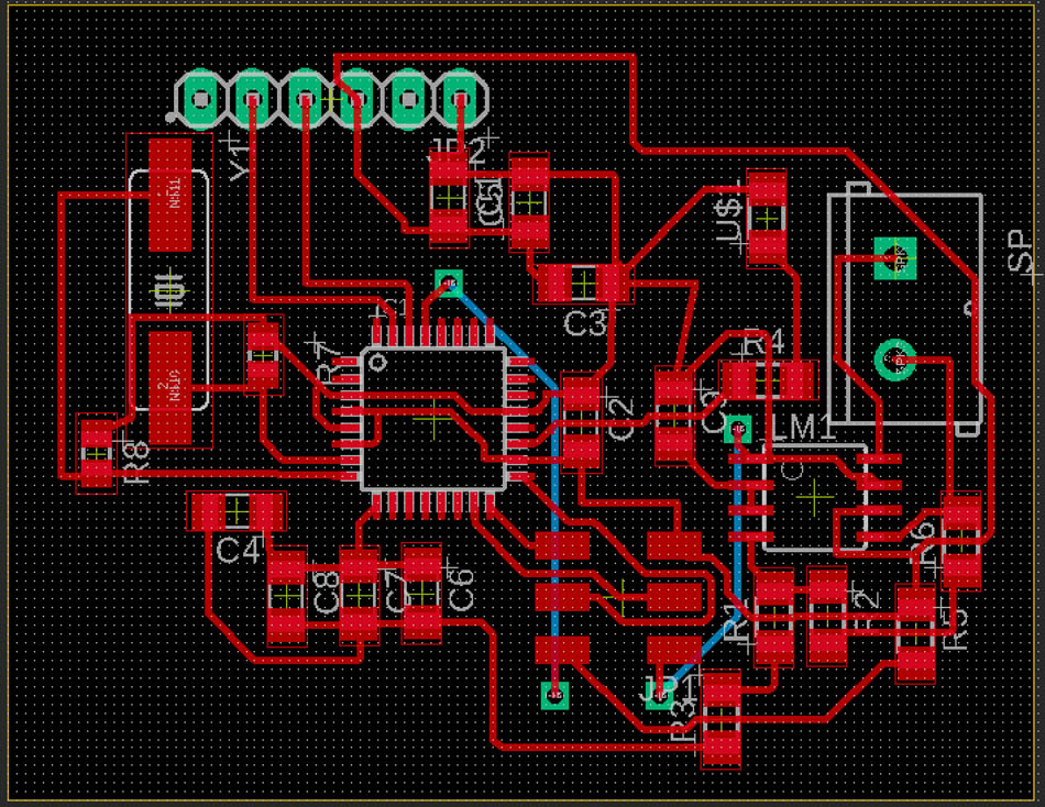
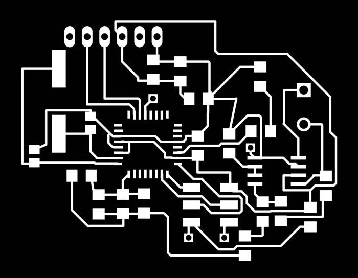
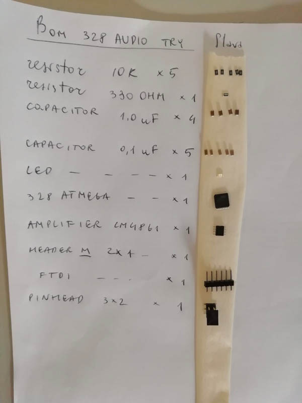
Electronics
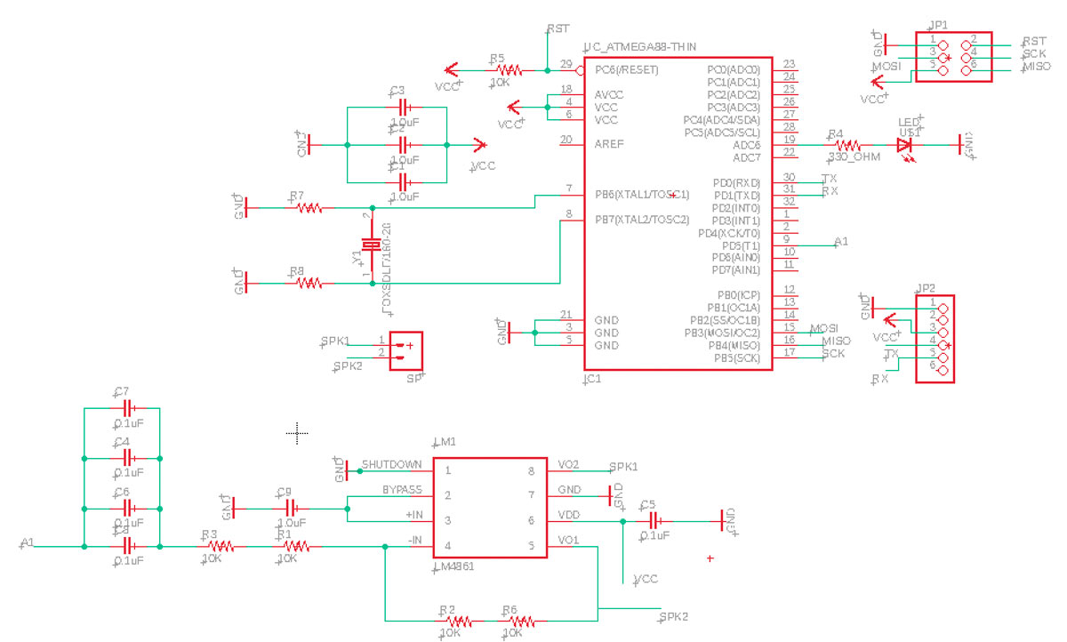
In order to try sound I milled a small board that contained ATMega328 and an amplifier LM4861 (datasheet). ATMega328 has an internal clock of 8000kH, my instructor suggested adding on the schematic also a cristall with resistors, but to solder them only if needed. To understand better how the audio is reproduced by arduino, how it works this video might be useful and this tutorial.
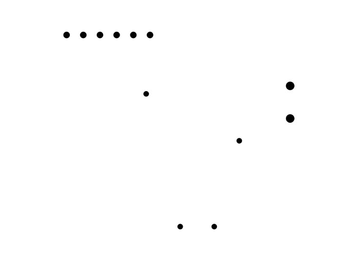
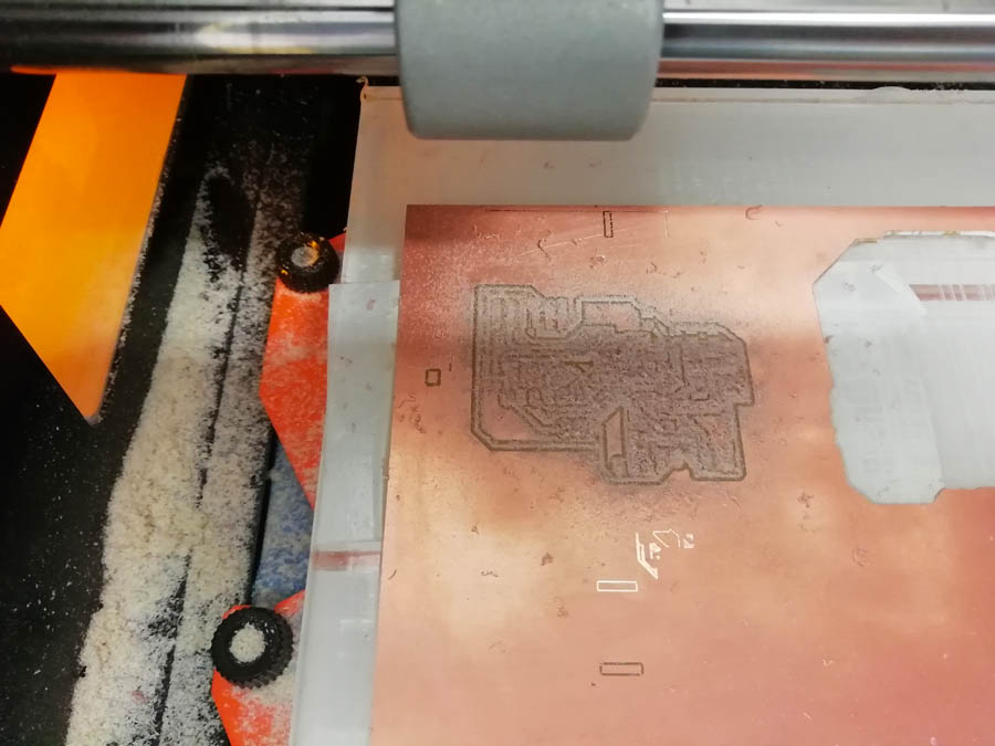
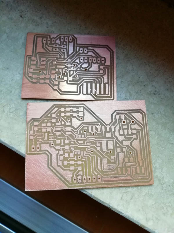
Then I prepared files for our milling Roland machine

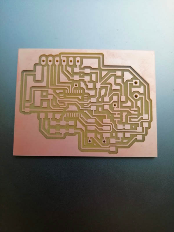
I would highly not recommend to do what I did here below. It was my first time soldering 328 and my head was blowing up. Basically, after leaving the solder on every chip's pin it took me then abour half an hour just to fix ATMega on the irregular surface of pins.
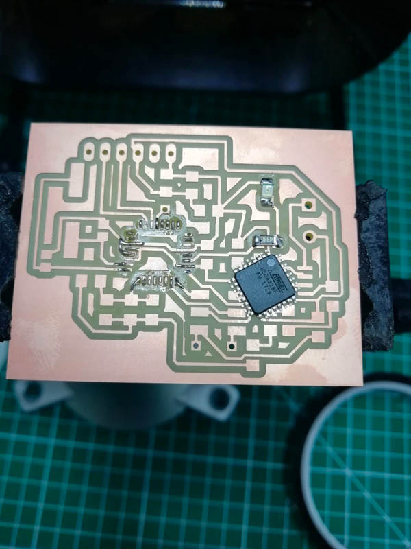
I used the configurations below to program my 328, when I wanted to make my Led blink, it would not work. My instructor noticed that I picked up the wrong pin for soldering (ADC6) that is in arduino datasheet ADC7:6 serve as analog inputs to the A/D converter. These pins are powered from the analog supply and serve as 10-bit ADC channels. For this reason it could no be programmed for output. As consequence, I decided to try directly audio, but since I was not sure my speaker was working I used tone() library for Arduino and followed tutorial from their officialwebsite. Another tutorial that can turn out to be usefull is this one.
Then I programmed the Led wiring it manually to the pin 1 and tried audio using the same code, but on my trial 328 with earphones.
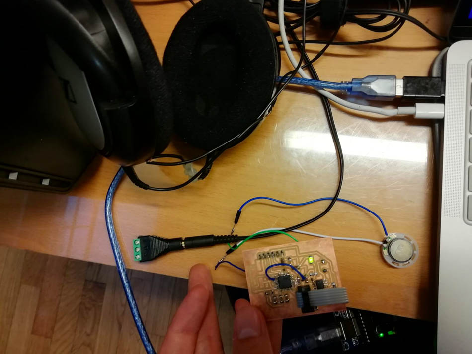
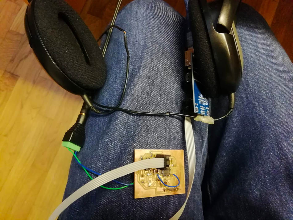
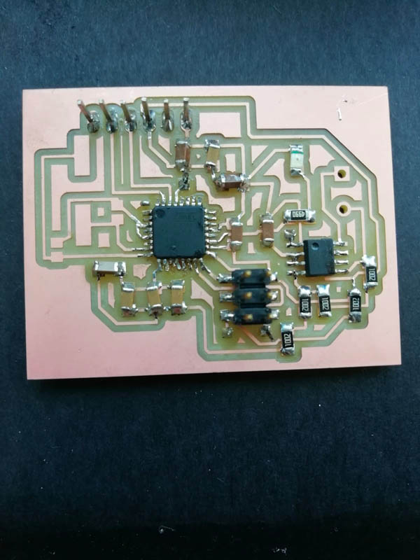
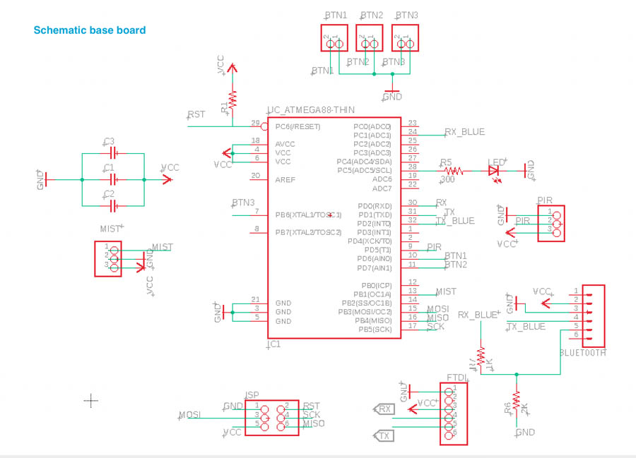
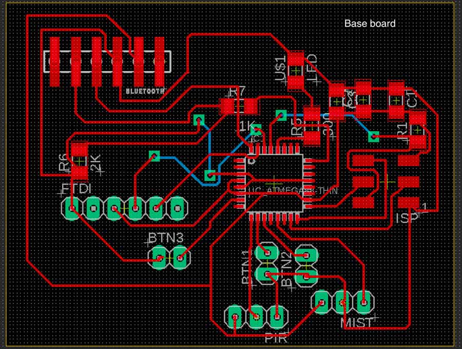
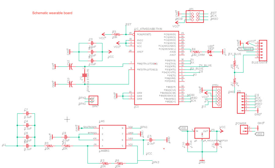
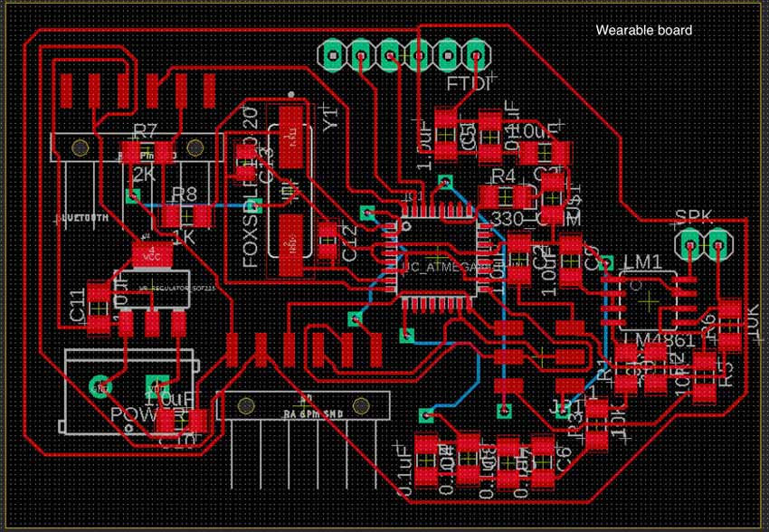
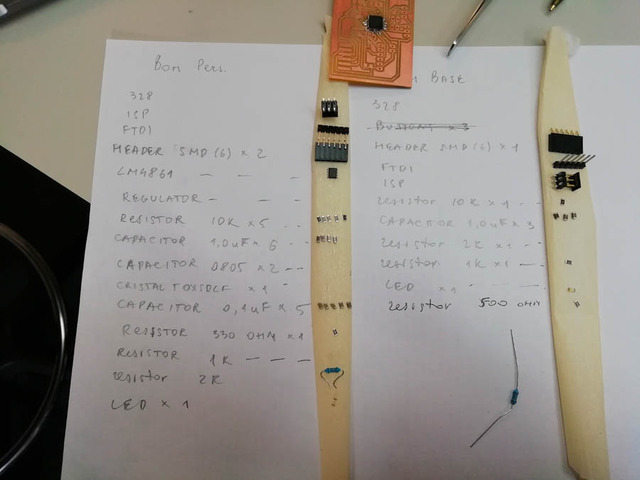
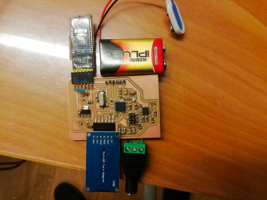
For my final project, I needed two boards: one with buttons, PIR and bluetooth module transmitter and another with earphone jack, SD card, bluetooth module receiver and a battery as it would be placed in a wearable case. For both boards I used AT Mega 328 and for the second I added an amplifier LM4861 as for the trial board and a regulator for the battery.
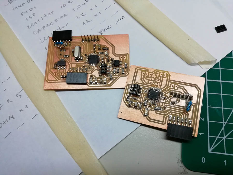
Once milled and soldered my boards, I tried to programm blinking Led and uploaded the following codes. The audio must be improved because the quality was not very good.
  //Base board

  #include <SoftwareSerial.h>

#define button1 2
#define button2 3
#define button3 4
int buttonState = 0;
SoftwareSerial bluetooth(11, 10);

const int pinPir = 5;
const int pinMist = 9;

bool firstAvvicinamento = true;

void setup() {
  pinMode(pinPir, INPUT);
  pinMode(pinMist, OUTPUT);
  digitalWrite(pinMist, HIGH);
  pinMode(button1,INPUT);
  pinMode(button2,INPUT);
  pinMode(button3,INPUT);
Serial.begin(115200);
bluetooth.begin(9600);
delay(100);
}

void loop() {
  delay(2000);
  if ((digitalRead(pinPir) == HIGH) && (firstAvvicinamento == true)) {
    firstAvvicinamento = false;
    pulseMist();


  }
//Button 1//

  if (digitalRead(button1) == HIGH) {
    bluetooth.write(1);

    Serial.println("Button is 1");
      delay(100);
      }


//Button 2//

  if (digitalRead(button2) == HIGH) {
    bluetooth.write(2);

    Serial.println("Button is 2");
      delay(100);
      }

//Button 3//

  if (digitalRead(button3) == HIGH) {
    bluetooth.write(3);

    Serial.println("Button is 3");
      delay(100);
      }

}

void pulseMist() {
  digitalWrite(pinMist, LOW);
  delay(100);
  digitalWrite(pinMist, HIGH);
  delay(5000);
  digitalWrite(pinMist, LOW);
  delay(100);
  digitalWrite(pinMist, HIGH);
}
  //Wearable board

  #include <SoftwareSerial.h>
  #include <SPI.h>
  #include <SD.h>
  #include <TMRpcm.h>

  #define SD_ChipSelectPin 4
  #define ledPin 2
  int state = 0;
  SoftwareSerial bluetooth(11, 10);
  TMRpcm tmrpcm;

  void setup() {
    tmrpcm.speakerPin = 9;
    pinMode(ledPin, OUTPUT);
    digitalWrite(ledPin, LOW);
    Serial.begin(115200);
    bluetooth.begin(9600);

  }

  void loop() {

    if(bluetooth.available() > 0) {
      state = bluetooth.read();
      Serial.println(state);
    }
    if (state == '1') {
     tmrpcm.setVolume(6);
     tmrpcm.play("1.wav");
     bluetooth.println('1');
       delay(10);

    }
    else if (state == '2') {
     tmrpcm.setVolume(6);
     tmrpcm.play("2.wav");
     bluetooth.println('2');
       delay(10);
    }
    else if (state == '3') {
     tmrpcm.setVolume(6);
     tmrpcm.play("3.wav");
     bluetooth.println('3');
       delay(10);
    }
    delay(1000);
  }
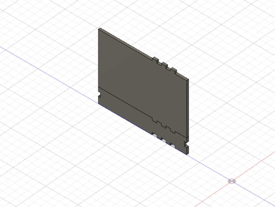
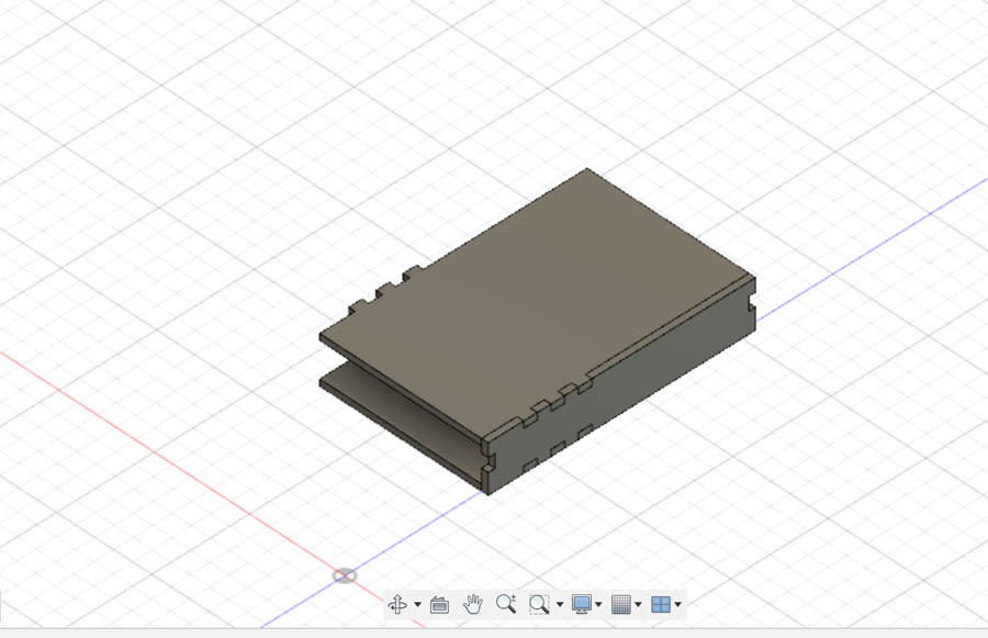
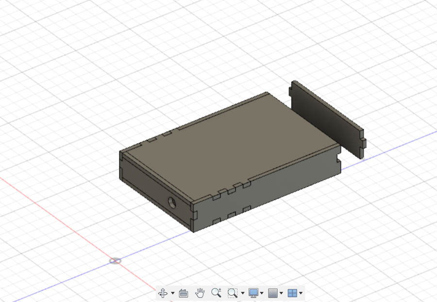
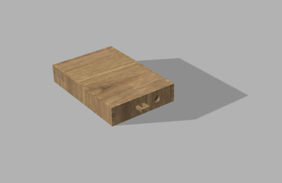
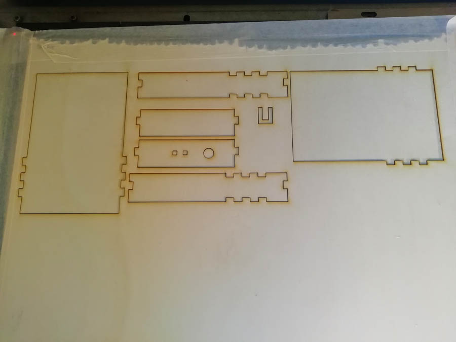
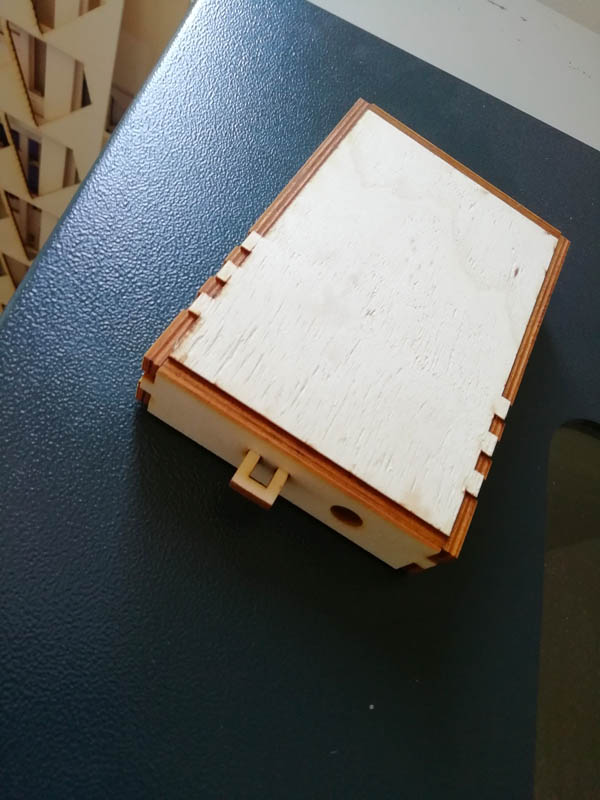
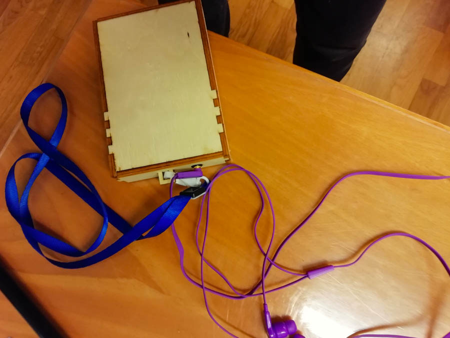
Case Design
In order to create the case, I first take the misures from the assembled board, then designed it on Fusion 360 and laser cut it.
Future steps and Development
My final project has arrived to an advanced state of a prototype, it is not quite a finished product, even though I am pretty satisfied considering time and issues that I have encountered during project development. There are a series of improvements that must be made: first of all, the bas-relief itself should be more detailed. In order to obtain a better result, there is a need of more precise work on displacement map and its preparation on photoshop where the areas of grayscale are identified that eventually become a relief. Once the model is prepared, for milling there is the need to repeat at least twice the finishing. One finishing took 10 hours, so it is also a hard work that must be done, more of machine control in this case. The audio did not work properly and the audio quality must be improved. Then I would also create a base for bas-relief where PIR sensor mist generator are placed.
Docs
You can download the zip package with files from here