Week 14
Individual assignment:
design, build, and connect wired or wireless node(s) with network or bus addresses
This week all hardware and software seemed to be against me, but anyway here I am.
I started with reading about serial communication, SPI, I2C networking.
What is serial communication?
Unlike parallel comumunication that streams huge amounts of data at the same time, serial communication stream information in form of one bit at a time.
I tried to use my Arduino as a programmer because it seemed to be easier to use, but actually it did not work. Arduino IDE would not recognise it as a programmer, even though I followed tutorials.
Afterwards I swithced to the programmer of the week4. (Un)surprisingly it dit not work either. The problem seemed to be the function that I used on Arduino IDE, that is burn bootloader. Basically, bootloader is a program that runs when the board is on, it does two things: if there is a programm on the computer to upload on the board it sends the programm, otherwise it runs the programm that is already on Arduino. In this way, there is no need for a device apart, it's an embedded feature that sends the program via the TX/RX serial pins, these pins are usually connected to a PC via USB cable.
What I found out is that when you burn bootloader before uploading a programm, it deletes fuses. In this way, the programmer that was supposed to be a master and on which I was uploading the code, got completely reprogrammed losing its primary role as a programmer. For this reason, I had to switch to a commercial programmer.
I2C communication
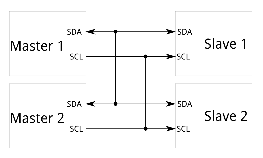
After researching on types of communication, I decided to focus and try I2C: synchronous serial communication protocol that permits a series of devices to exchange their data using only two wires, where one is used for data and another to synchronise communication. In fact, it is also called TWI (two wires interface), because it uses SDA for serial data, SCL for serial clock, GND and VCC.
So I tried to make communicate one of my hello world boards from previous weeks and Arduino. In order to do that it is necessary to install proper libraries for Arduino IDE: TinyWireM can be found directly from IDE, whilst TinyWireS I downloaded from github. I had had new version of Arduino 2.0 Beta that could not recognise the installed library which I downloaded. This is why I had to change IDE version to 1.8 and fortunately it worked.
Then I wrote the code for master:
  #include <Wire.h> //library for master
#include <SoftwareSerial.h>

SoftwareSerial mySerial(0,1); //define SoftwareSerial

void setup() {
mySerial.begin(9600); //baud rate
Wire.begin(); //initialise master's library
delay (300);
}

void loop(){
mySerial.println("is it working?");
Wire.requestFrom(4,1); //request 1 byte from slave's address 4
while (Wire.available()) { //check if there any bytes available
int n = Wire.read(); //read the value
mySerial.println(n); //print the value
}
delay (600);
}
Here below the code for slave:
  #include <TinyWireS.h>

void setup ()

{
    TinyWireS.begin(4); //slave address is 4
    TinyWireS.onRequest(test); //request data from slave
}
 void loop ()

 {
  TinyWireS_stop_check();
 }
void test ()

{
  TinyWireS.send(2); //number to transmit
}
Bluetooth
For several weeks I had been trying to figure out bluetooth communication, since there were some issues over and over again, so this is a huge summary of all it.
First of all, bluetooth modules that I got were HM-10 and in order to programm them it is necessary to study their datasheet, some commands can vary comparing, for example, to HC-05, that's why it is crucial to pay attention. By default, all modules are set as slaves. Here you can find complete datasheet, while here the reduced version of it.
The first issue was to pair two modules. First, I connected one of them to FTDI cable and through serial monitor with baud rate 9600, since it is the default rate used by modules, programmed the slave:
AT command to test if device is connected, if the result is positive you'll see OK, then I used AT+RENEW and AT+RESET to restore all setup value to factory setup and reset the module. To be sure I also used AT+ROLE? to know if it is a master or slave, after reset naturally it was slave, so I got 0. After that I digited AT+ADDR? since I needed the address in order to programm the master later. As I had some issues in pairing them I also used AT+MODE0 to set work mode for transmission, even though it should have been 0 by default, but most importantly it solved an issue eventually.
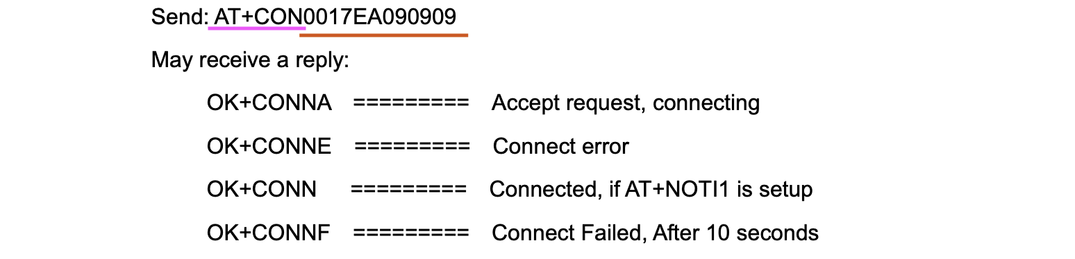
With the second module I repeated first 4 commands and typed AT+CON followed by the address of slave module that I had saved before. For example, as mentioned in datasheet below.
For general wiring I used this tutorial, also this tutorial might be useful, but due to the issues I kept basic wiring to see if two modules pair and first wrote a code just to send a number to check if they transmitted data. It's important to switch RX and TX, so to connect RX to TX and vice-versa and to use as baud rate for serial port 115200 for arduino and 9600 for bluetooth. It took way too many days of puzzling to figure this out by my instructor Simone and me.
Slave code:
  #include <SoftwareSerial.h>

SoftwareSerial bluetooth(11, 10); //RX, TX;

void setup() {
Serial.begin(115200);
bluetooth.begin(9600);
delay(100);

}

void loop() {


    bluetooth.write("1");

}
delay(1000);
}
Master code:
  #include <SoftwareSerial.h>


int state = 0;
SoftwareSerial bluetooth(11, 10);

void setup() {
  Serial.begin(115200);
  bluetooth.begin(9600);

}

void loop() {
  if(bluetooth.available()) {
    Serial.println(bluetooth.read());

  }
  delay(1000);
}
In the video below you can see how the module sends 1 and master receives it in ASCII as 49 followed by 2 bytes 10 and 13.
The continuation of my work and tries with bluetooth communication are reported on project development page.