5. Electronics production
Assignment: Characterize the design rules for your PCB production process
Basic concepts PCB fabrication
For the preparation of this week's task, we received help from a colleague at the university who has knowledge in the processes related to PCB cards and the creation of electronic cards. We started the process with theoretical foundations regarding the basic concepts related to electronic cards. First, we started a practical job with an MB102 830 points breadboard. A breadboard is a construction base for prototyping of electronics. Because the breadboard does not require soldering, it is reusable. This makes it easy to use for creating temporary prototypes and experimenting with circuit design.
Steps:
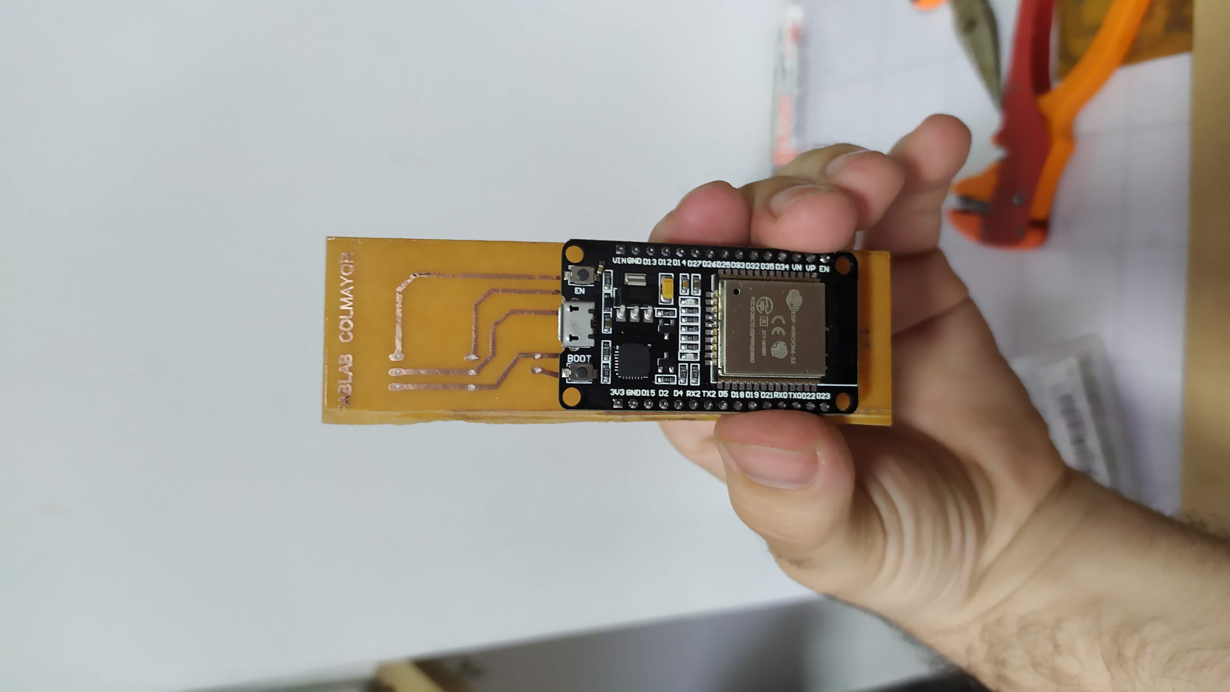
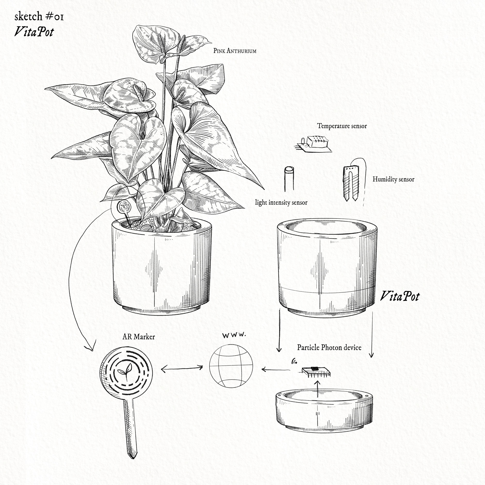
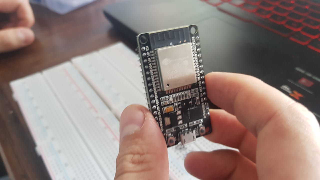
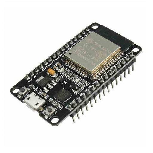
- We take as a reference which electronics element we want to use, in our case an ESP32 , with integrated Wi-Fi and dual-mode Bluetooth technology.
- We used an electronics prototyping board to understand what were the wires we needed to join.
- The mechanism is focused on light detection and depending on the intensity the device moves by means of a servomotor.
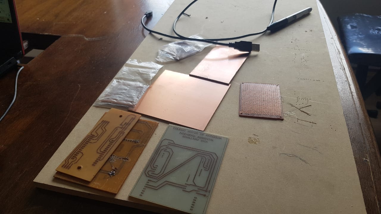
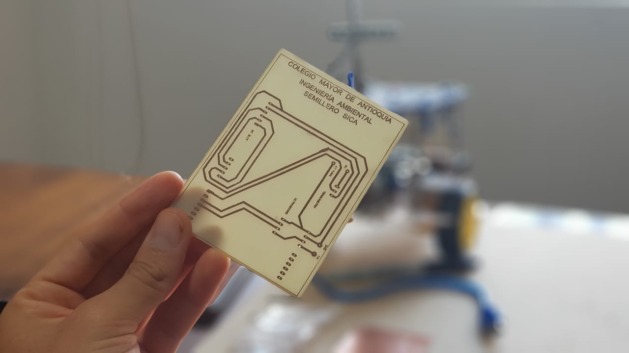
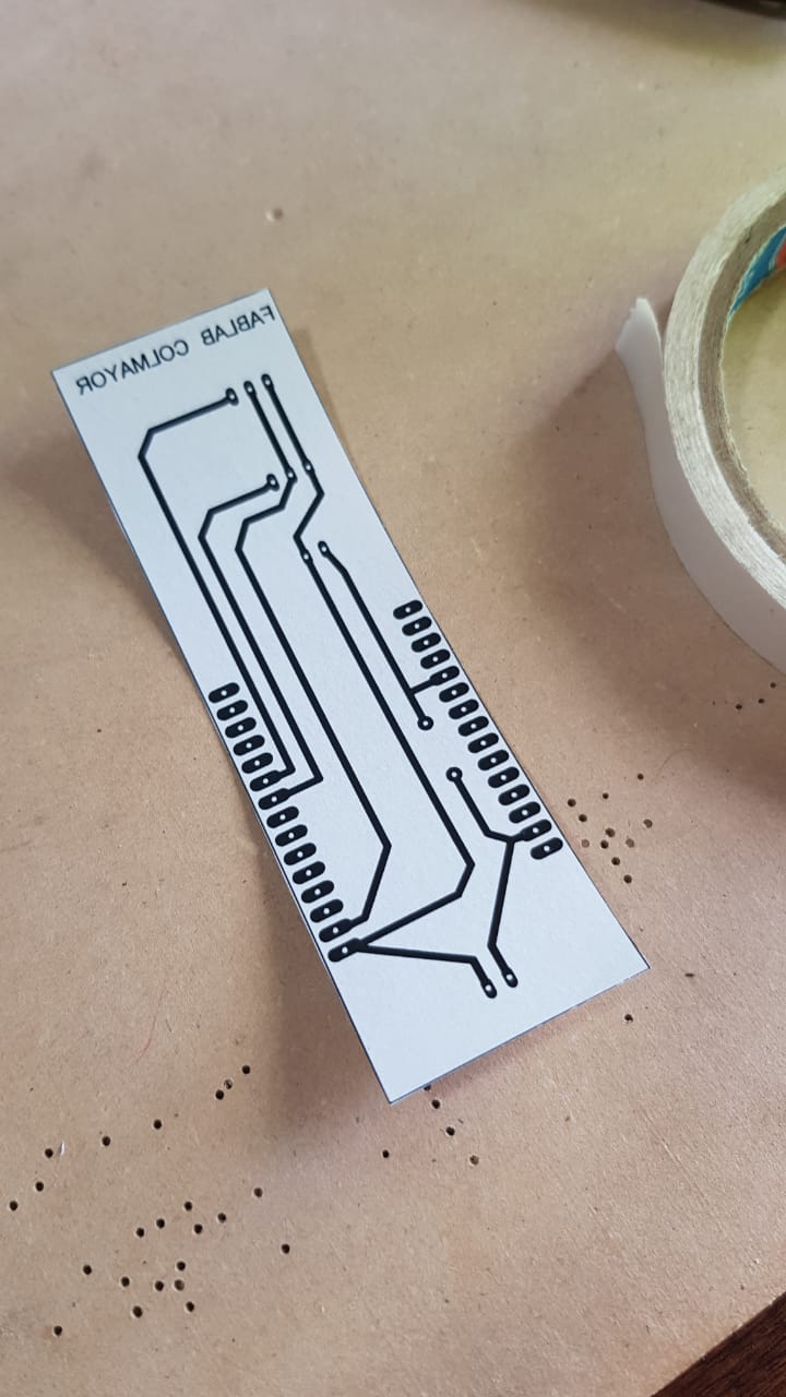
- In the PCB Wizard program the design was created based on the measurements of the PCB board available.
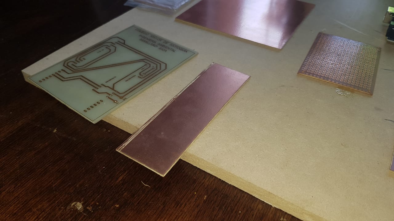
- It is printed on a transfer paper (the printing or design of the circuit is upside down to be able to paste it and that it is on the right side)
- Glue it to the board and use heat for about 10 minutes to transfer the ink to the board.
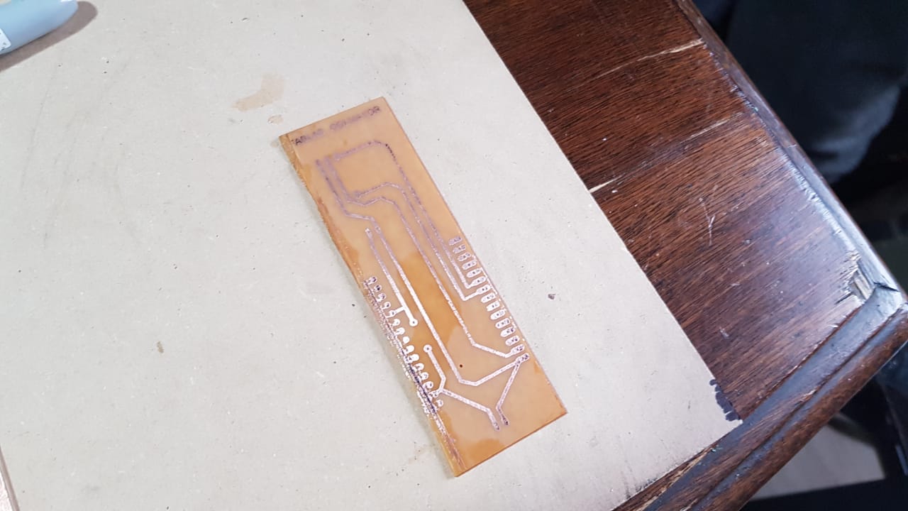
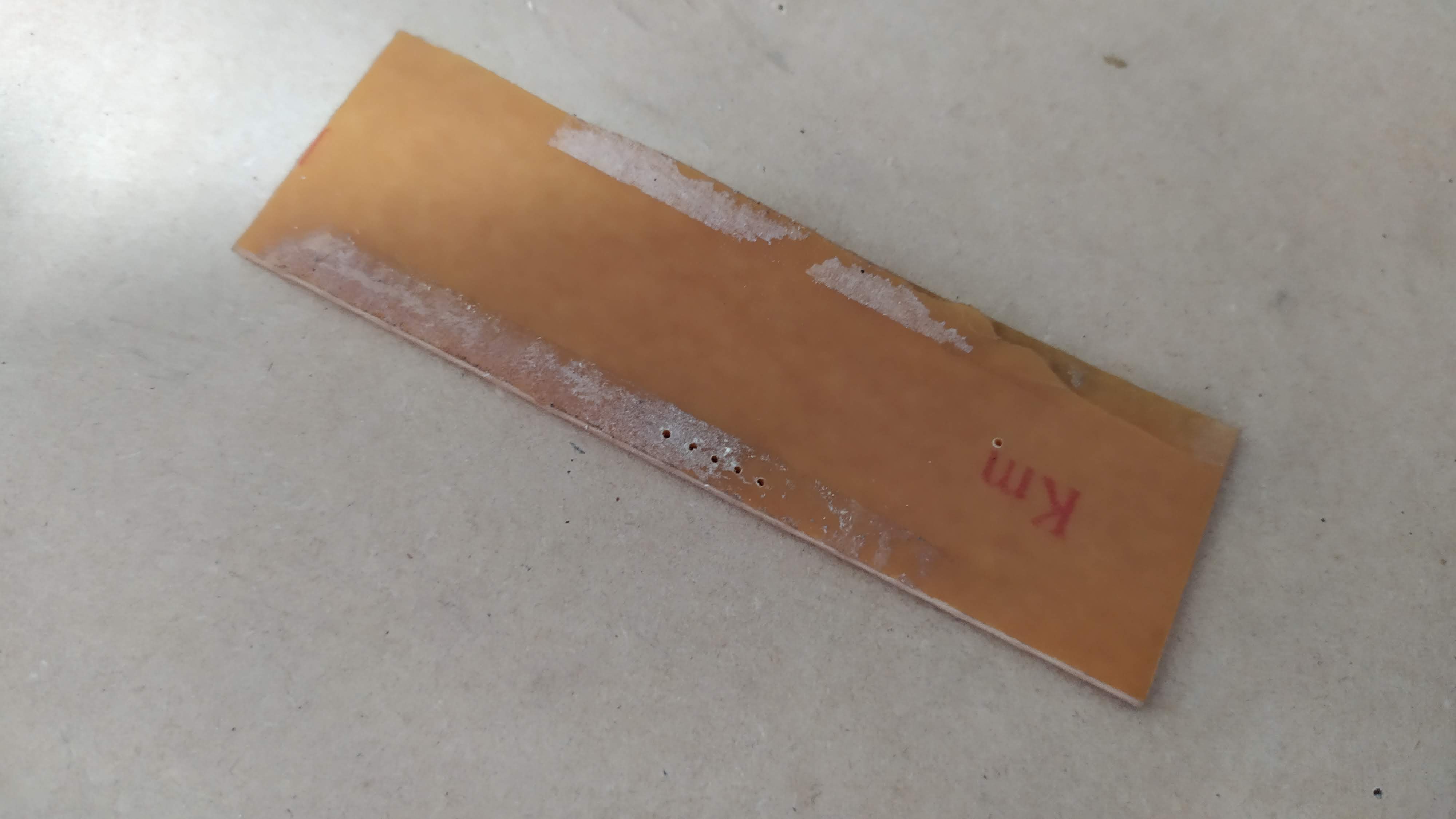
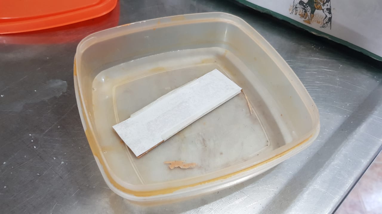
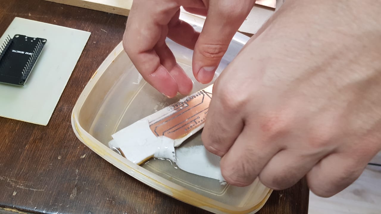
- Remove the excess paper and wash it.
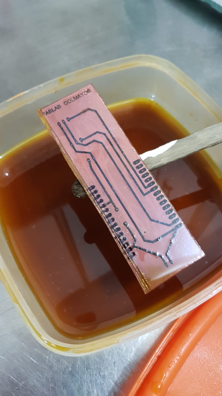
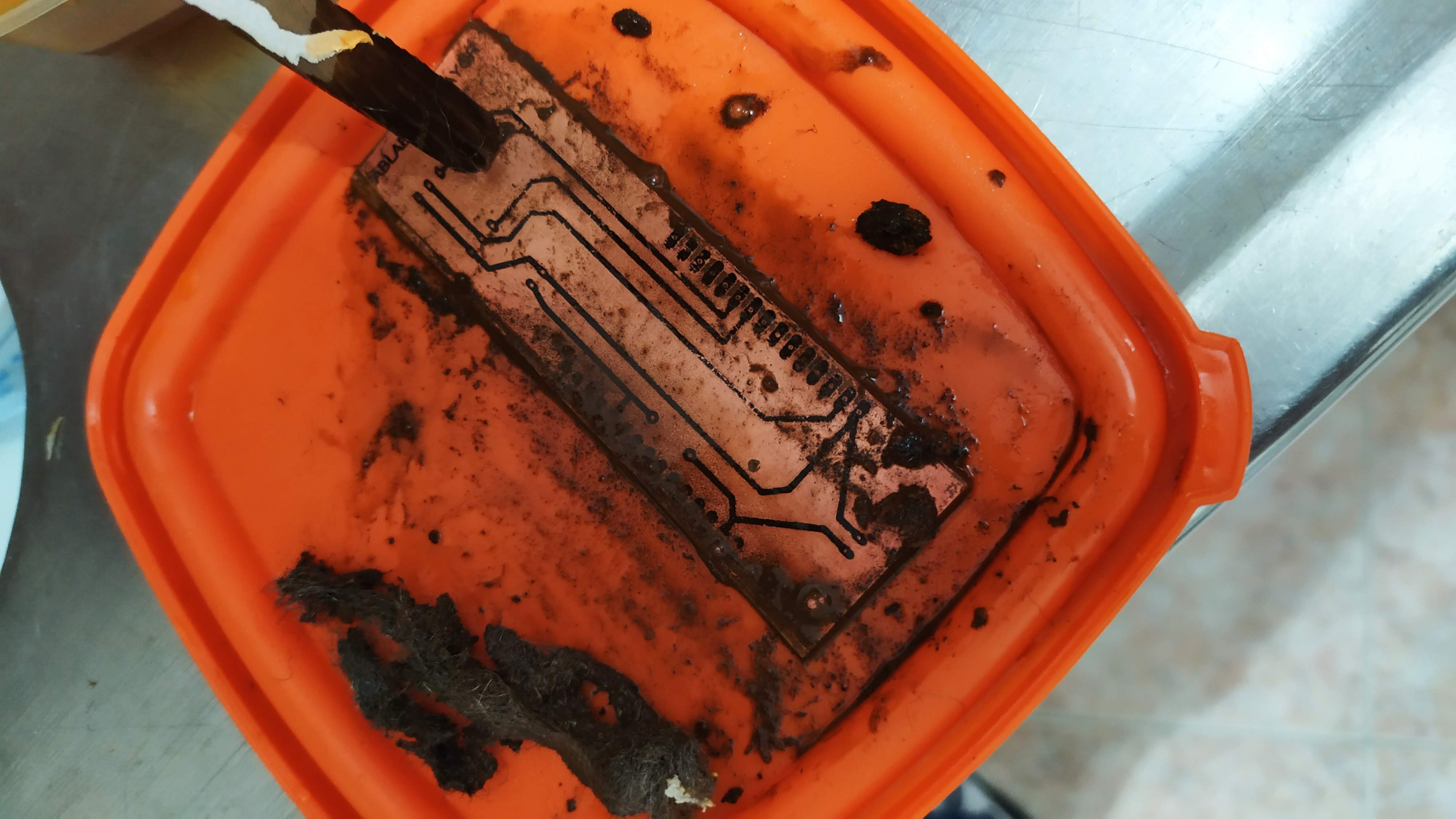
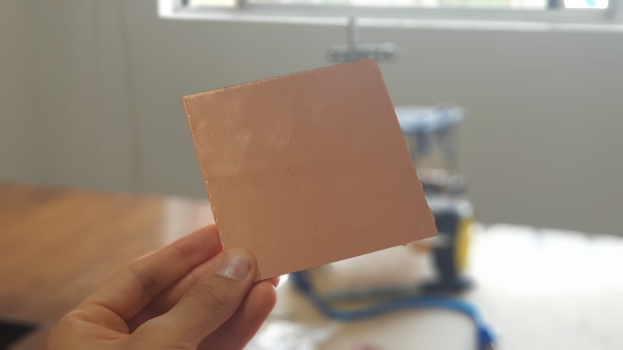
- Dip for the necessary time in ferric chloride until the excess copper is removed.
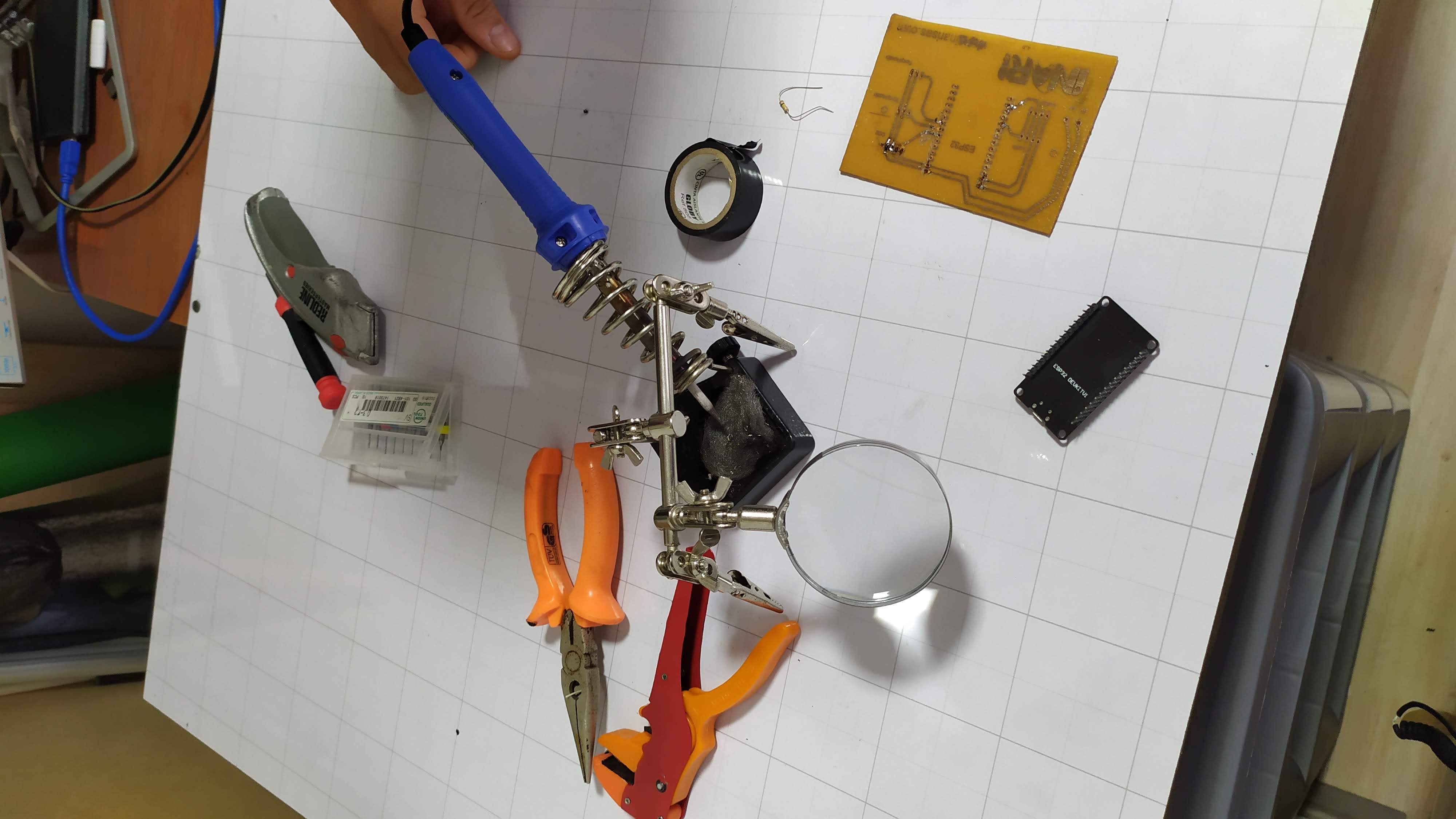
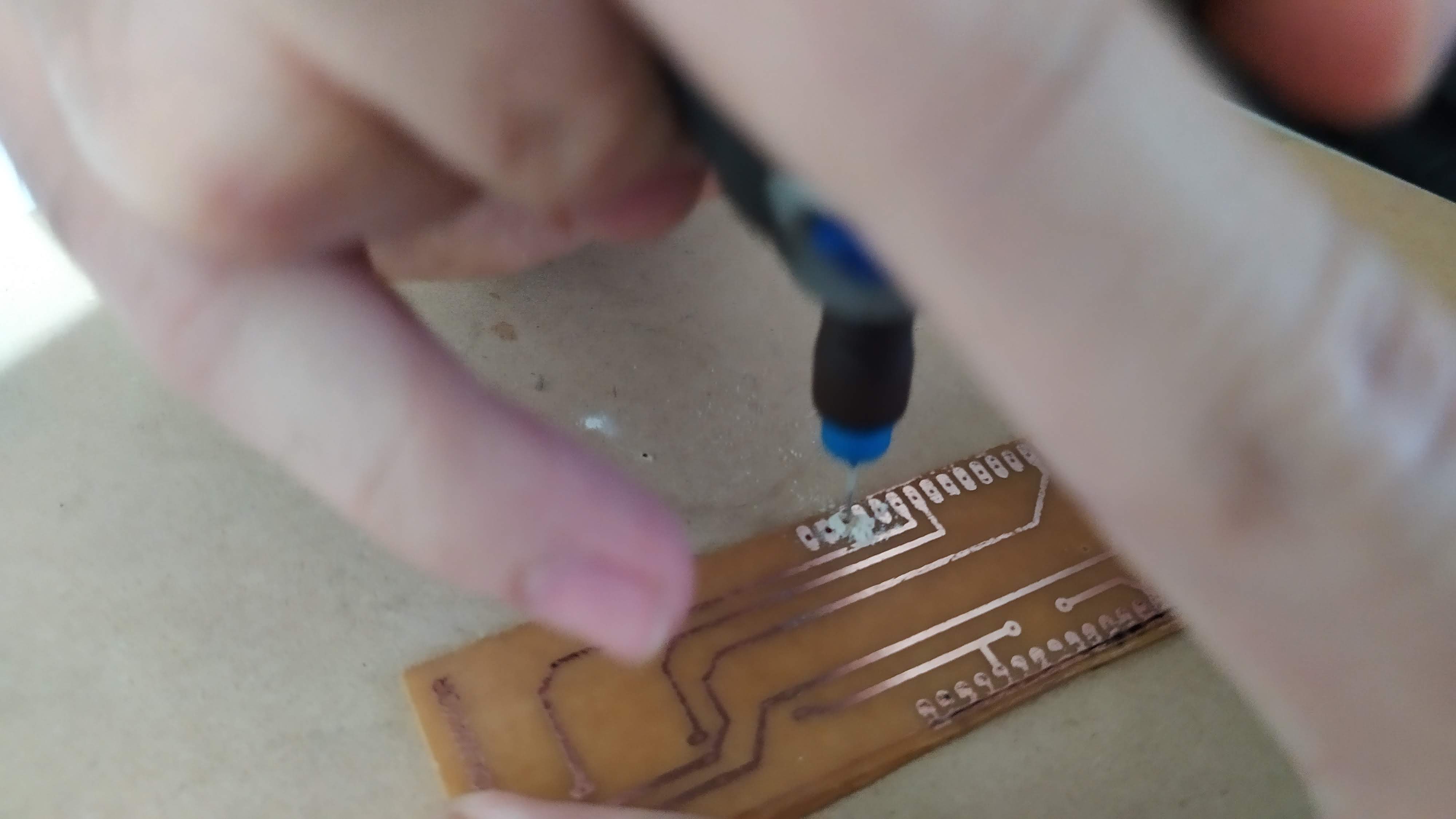
- A motortool is used to open the perforations to place the ESP32

For this practical exercise, we use an ESP32 microcontroller with Wi-Fi and built-in Bluetooth. This microcontroller is inexpensive and allows you to easily test with sensors. The ESP32 works with the Arduino IDE with the installation of the ESP32-Arduino Core and the integration between these two is remarkable. Once you install the ESP32-Arduino Core, you get access to a large variety of development kits that are based on the ESP32, and you also get a lot of example sketches.
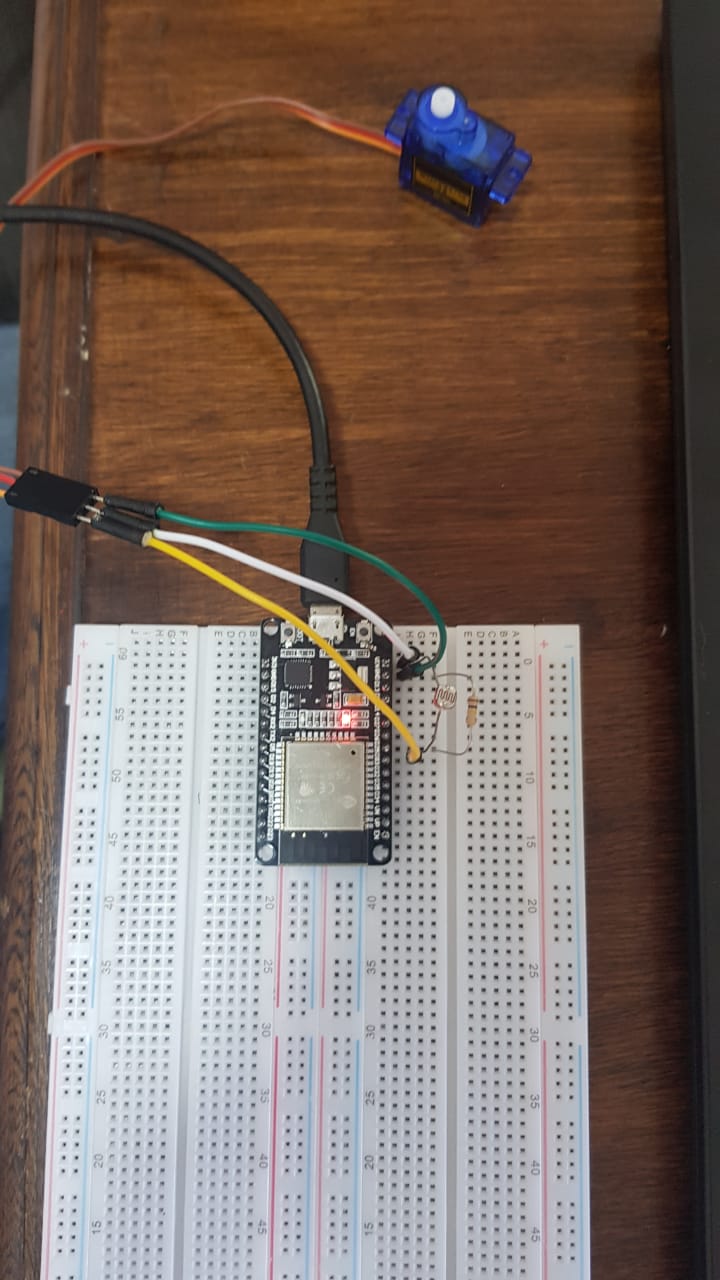
We proceed to install the microcontroller to the breadboard and start the design of our card. The idea is to connect a brightness sensor to the ESP32 to capture the resistance data in an analog signal that we will then interpret from the code in C. This data will be read in the Arduino software via a USB cable. As the card works with 5V, when connected via USB via the computer, it is perfect for powering the microcontroller and sending the data to the program.
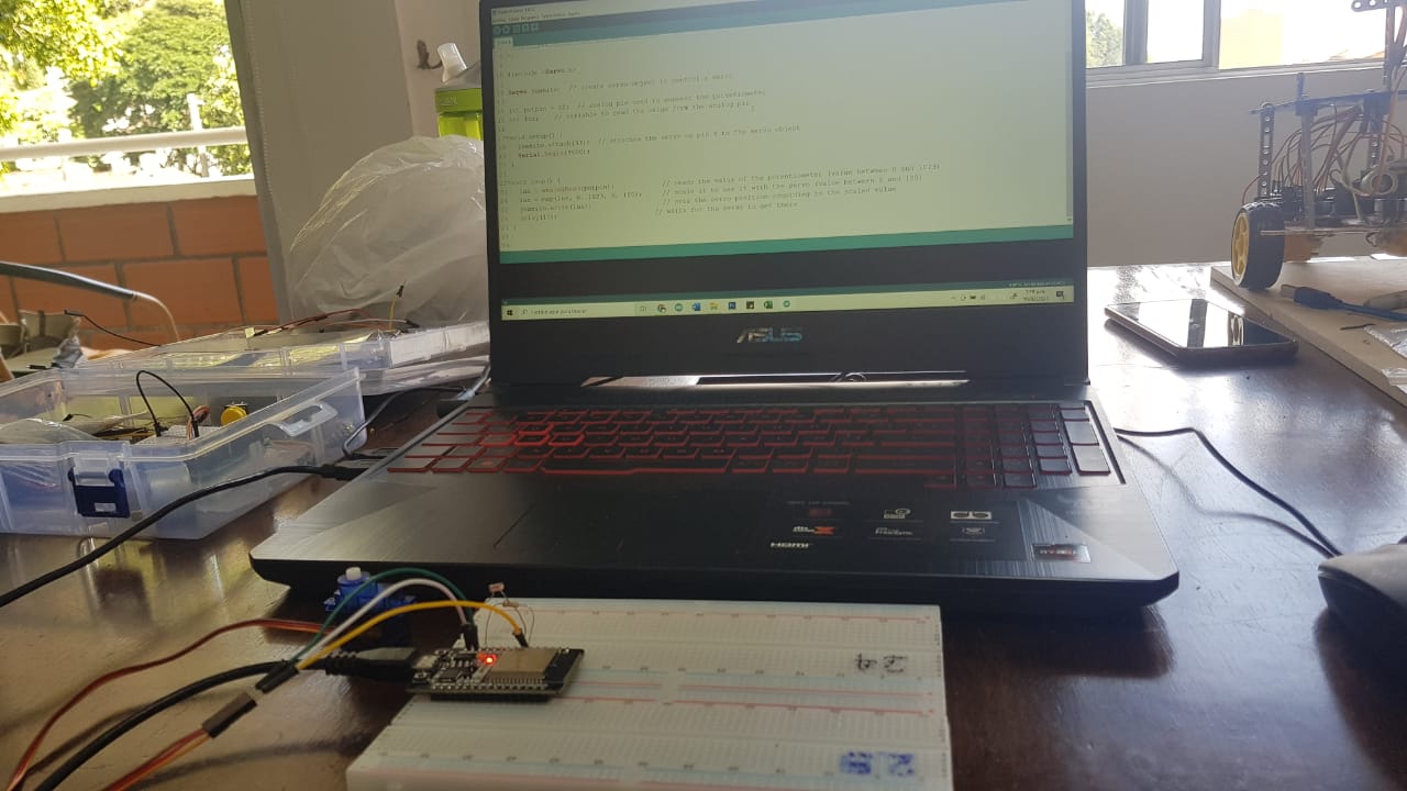
We proceed to install the microcontroller to the breadboard and start the design of our card. The idea is to connect a brightness sensor to the ESP32 to capture the resistance data in an analog signal that we will then interpret from the code in C. This data will be read in the Arduino software via a USB cable. As the card works with 5V, when connected via USB via the computer, it is perfect for powering the microcontroller and sending the data to the program.
ESP3
Webpage: https://www.espressif.com/en/products/socs/esp32
We proceed to install the microcontroller to the breadboard and start the design of our card. The idea is to connect a brightness sensor to the ESP32 to capture the resistance data in an analog signal that we will then interpret from the code in C. This data will be read in the Arduino software via a USB cable. As the card works with 5V, when connected via USB via the computer, it is perfect for powering the microcontroller and sending the data to the program.
Exercise process
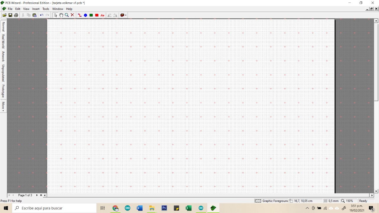
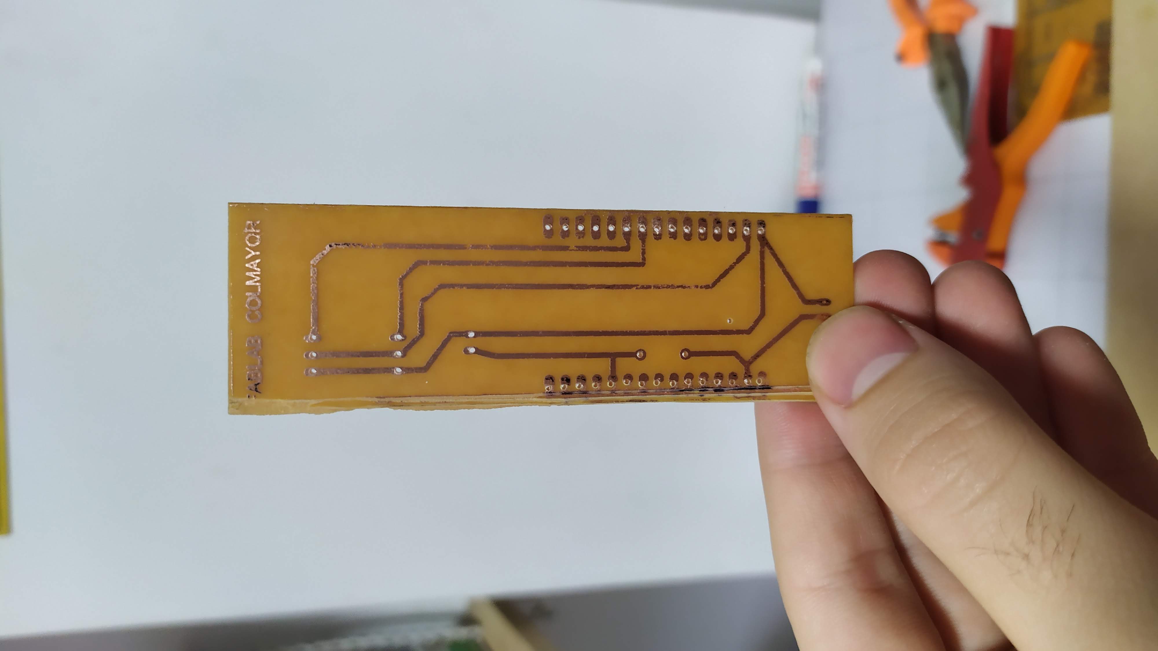
For this test we are using a single side PCB with dimensions of 5 cm x 18 cm
For this test we are using a single side PCB with dimensions of 5 cm x 18 cm
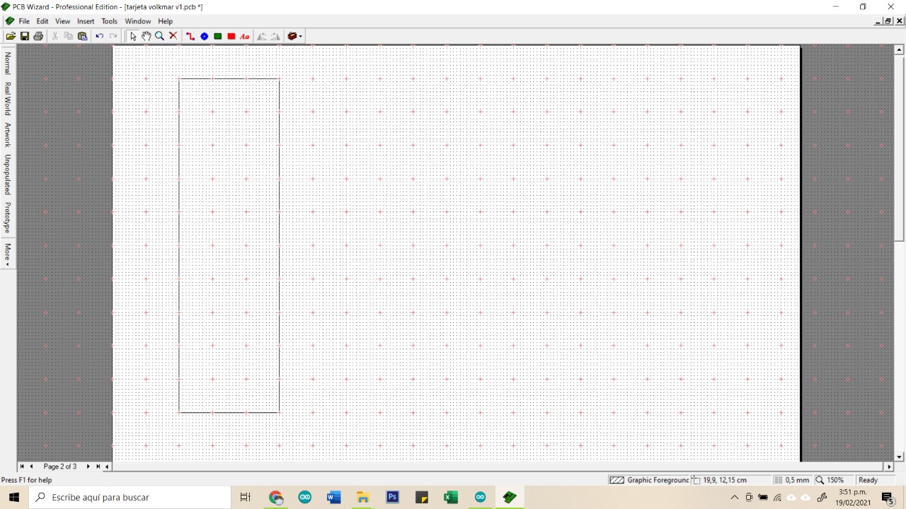
So for the design, we draw the dimensions of the PCB inside PCB Wizard
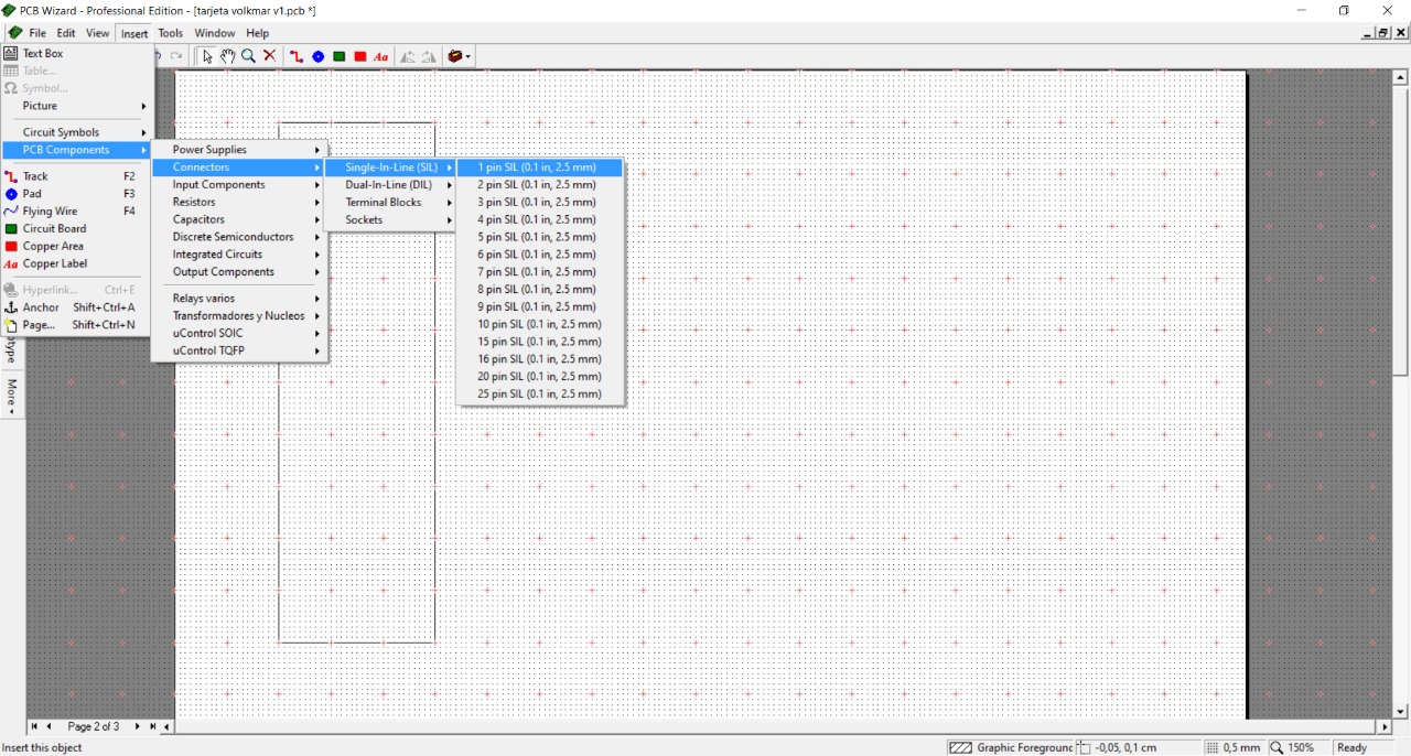
As for this exercise we will use the ESP32, we need to design the space to be able to locate this component, then let's go to the insert/PCB Components/Connectors/Single-In-Line/15 pin tab
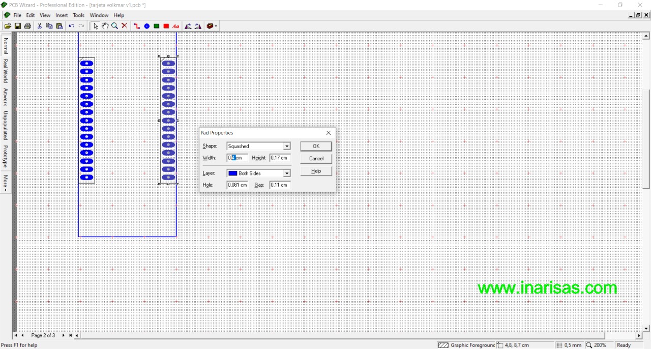
Then, we design the space for the sensors and devices that we want to connect.
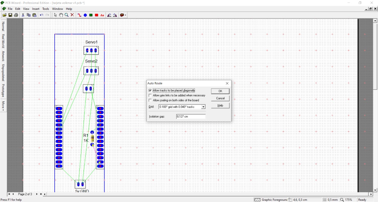
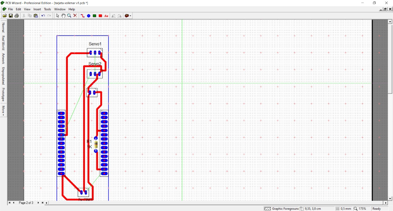
To draw the connections, we use a program tool called "Auto Route" This tool will calculate the routes based on the parameters that the program has for the construction of electronic cards. These parameters can be modified depending on the project.
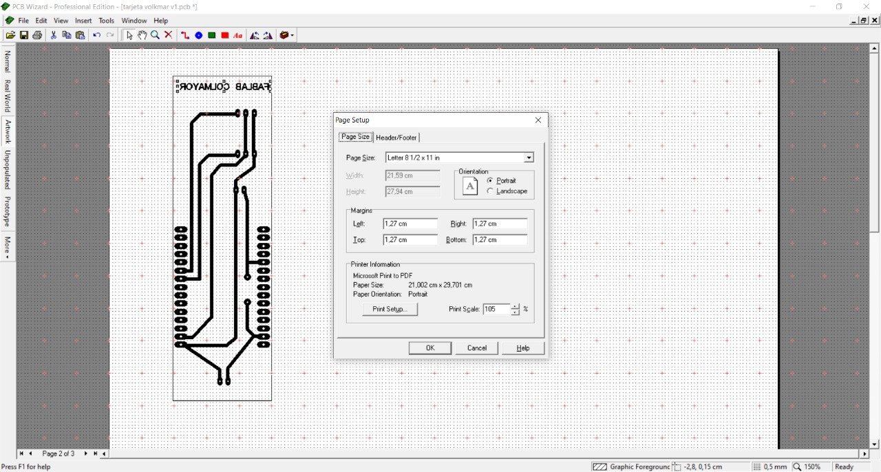
After the design is complete, we proceed to print it on a transfer paper.
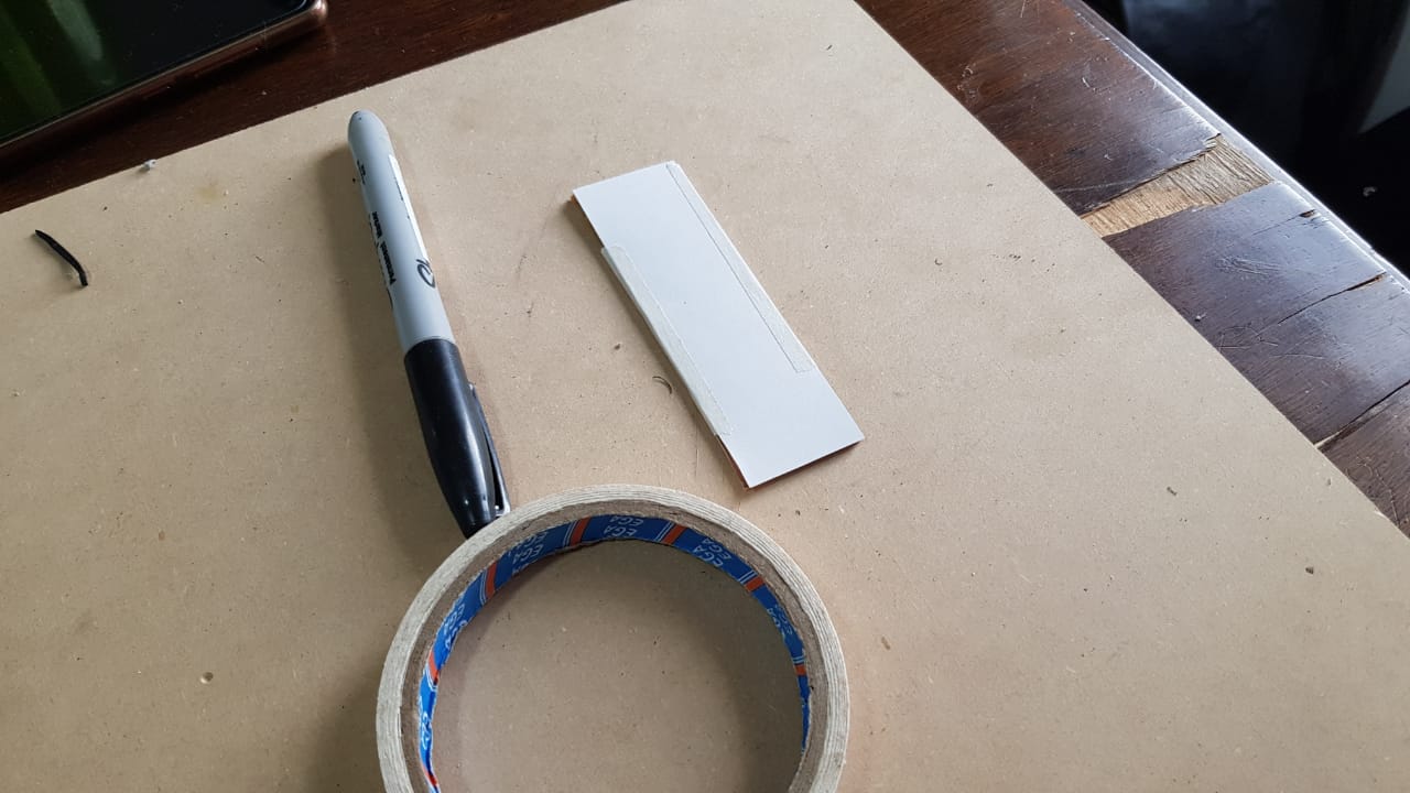
Using a clothing iron, we transfer the design to the PCB.
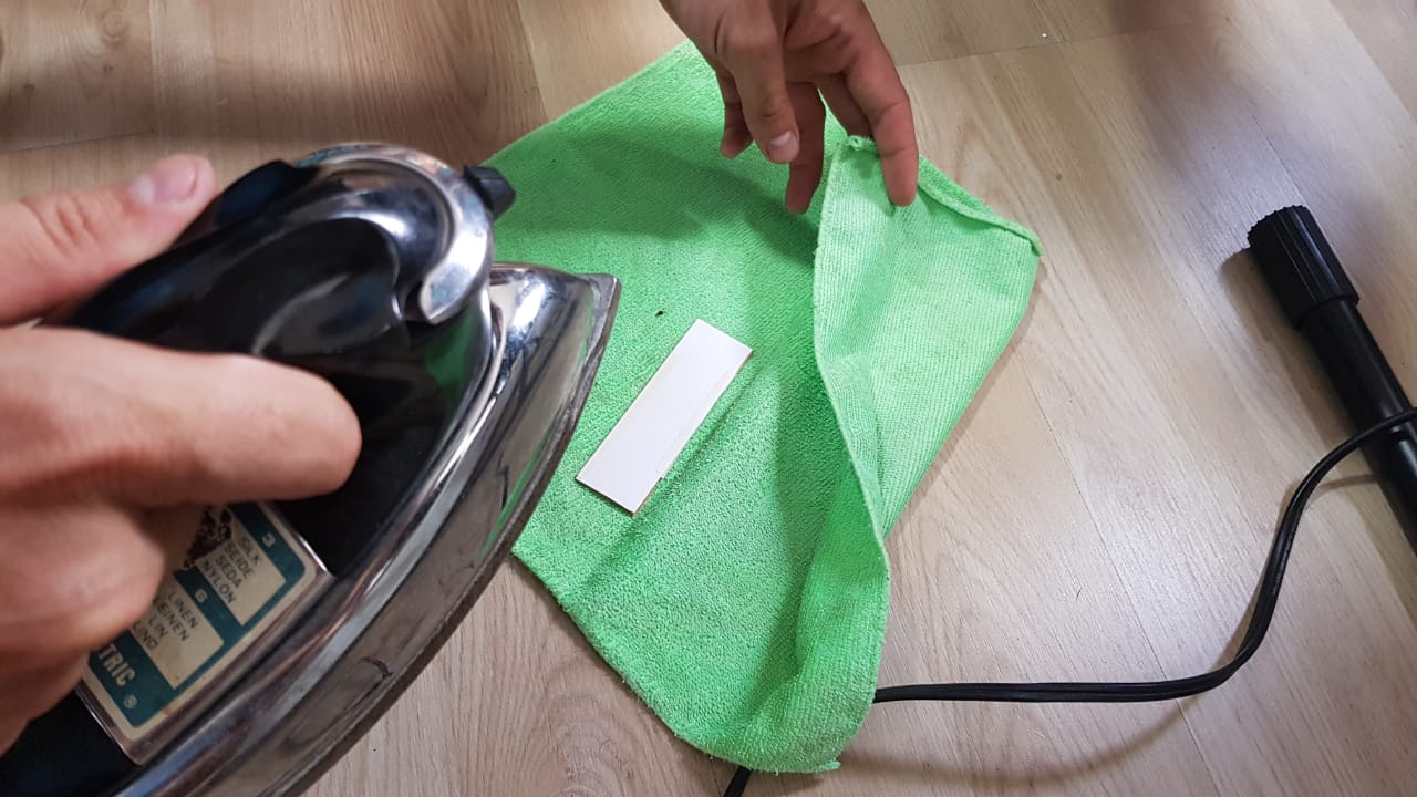
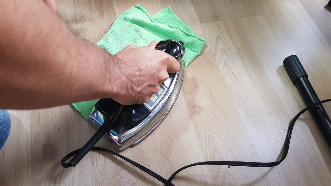
Using a clothing iron, we transfer the design to the PCB.