Applications and Implications
What will it do ?
The main idea of Axolbot is to have set of pieces (sensors, actuators and accesories) to build different types of robots using a clip and play system. These parts can be used to created: a two wheel robot, a spider with 4, 6 or 8 legs, a humanoide, etc. It is not my first time building something for education purposes, and I have learnt a few things that I considered as important to learn when starting in the electronics or robotics field.
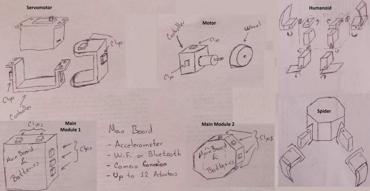
The set must have the following parts to accomplish specific objectives:
- Main module: contains the mother board, the output board and a voltage regulator. These components are used as hub central where the input is the voltage and the code which was previously programmed and the output is the different types of actuator that want to be controlled.
- Servomotor module: It is a module that can hold a MG90S metal gear servomotor and transmit the shaft movement. It is composed of two parts the holder and the moving C-profile
- Motor module: It is a module that can hold a metal gearmotor which has a pre-fabricated wheel
- Acceleromenter module: It is an electronic board that has a MPU6050 and an ATtiny45 connected with I2C protocol. The ATtiny is programmed to send the state of a digital input when the master requires it.
- Spider leg: It is a component that assembles the tip of a spider leg and that can be placed into the servomotor module.
- Free-wheel: It is a component that is used instead of a free wheel in the car mode
I chose two actuators, a servomotor and a gearmotor. The reason I selected the servomotor is that it requires a PWM signal with an specific pulse width to control the shaft position. On the other hand, I chose the gearmotors because they use a PWM signal to control the speed of the motor and a digital signal to control the direction of rotation. Moreover, the servomotors and the motors are the most widely actuators used in these days.
Talking about the sensors, I adapted the board to read an acceleromenter and be able to read another digital or analog sensor such as proximity sensors, microphones, light sensors, etc.
Besides the principles of the sensors and actuators, the robot uses an ESP-32 which can be programmed using the Arduino IDE and most importantly can be accessed via bluetooth and/or WiFi
Who has done that beforehand ?
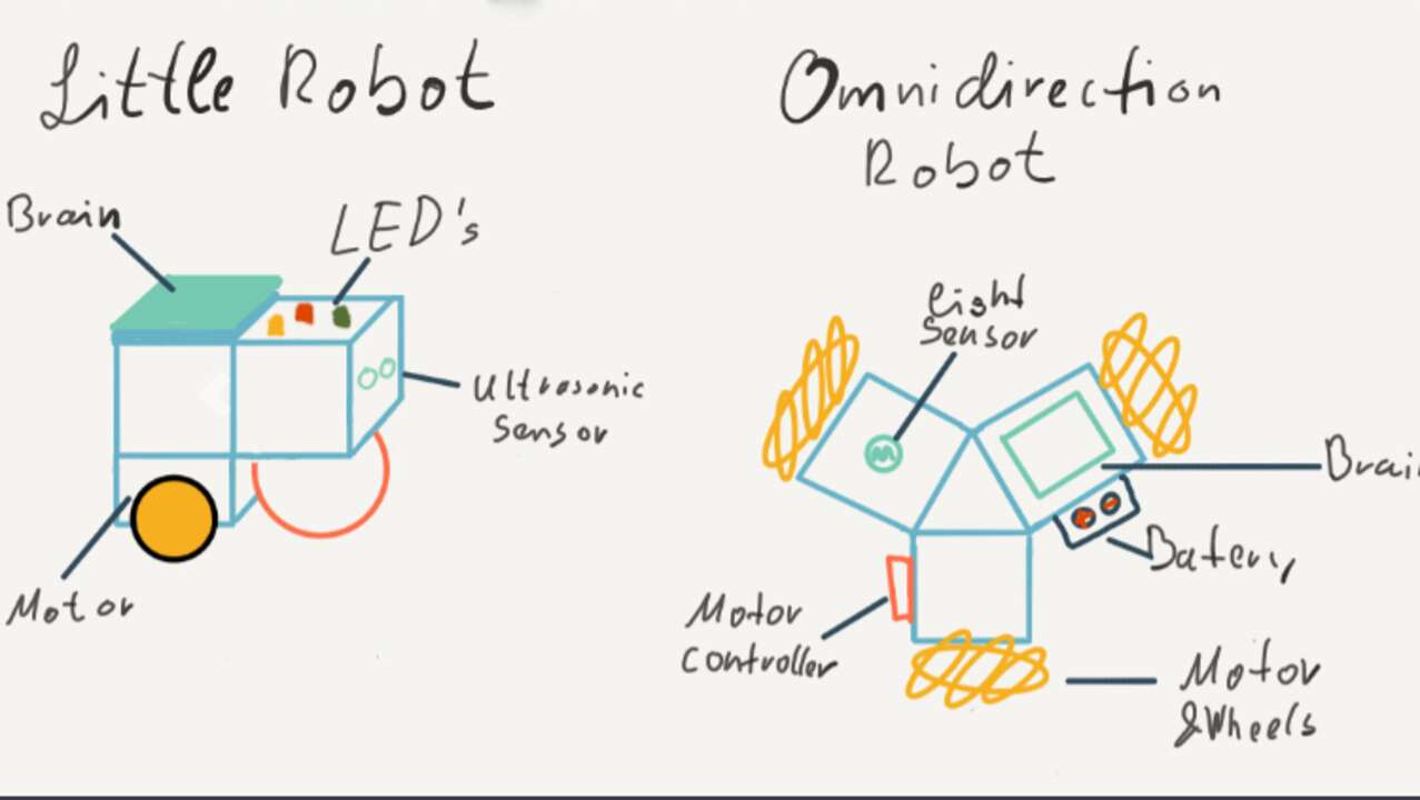
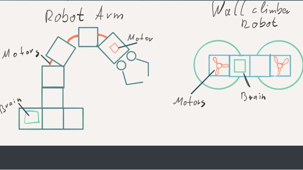
There are two main robots that were created in FabAcademy and I used them to got some ideas about the final product. The first one is called Morph3Dbot and it was developed by Lena Hagenauer in 2020. The robot is a modular cube system with 3D printed parts that can create multiple robot and can achieve multipele purposes depending on the attached cubes. The following photos show some possiblities that can be created with this system
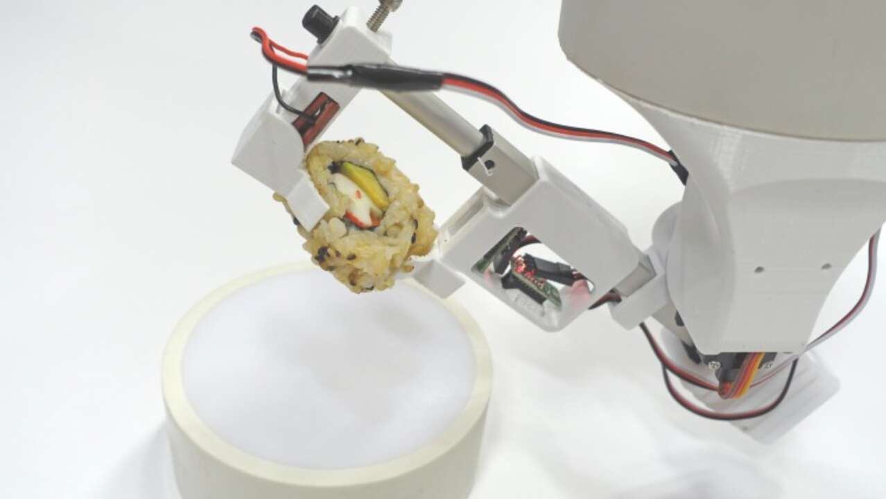
There is another prohect that I used for inspiration which is called Sushi robot. This robot can use multiple accesories to accomplish the required task and the robot is shown below
What will you design ?
I will design every electronic board but the power board (step-down voltage regulator) that reduces the battery voltage from 7.4V to 5V that is required in every board. I will not design this board because it requires many stages to provide with the enough current that the whole robot might requires. The main reason that the robot might requires a lot of current is because it can manage up to 16 servomotors at a time and the necessary current cannot be provided by a single 5V regulator.
Regarding the mechanical design, I will create all the components, parts and accesories using a 3D printing machine. The program of the robot will also be created by me, but there are some parts where I used libraries or tutorials to accomplish the set goals.
What materials and components will be used ?
The systems where I require materials or components is in the electronic and mechanical system.
- Mechanical design:
- 1 Coil of PLA or ABS
- 36 Bolts of 2 mm x 10 mm
- 16 Servomotor MG90S
- 2 Motors Copal
- 2 Wheels for copal motors
- Electronic design: I will divide the electronic system depending on the boards For the main board:
- 1 ESP32-WROOM
- 1 Regulator 5V
- 1 Battery of 7.4 V @ 1.5 A
- Other consumables(leds, resistors, capacitors, LED, etc.)
- 1 PCA9685
- 2 DRV8833
- Other consumables(leds, resistors, capacitors, LED, etc.)
- 1 ATtiny45
- 1 MPU6050
- Other consumables(leds, resistors, capacitors, LED, etc.)
Where will they come from ?
The electronics came from Mouser electronics, SanDoRobotics, FabLab Puebla and Mercado Libre. The PLA, bolts and servomotors came from Mercado Libre. Finally, the motors and their wheel I did not buy them now because I had them from the past but I got them from RobotCombat
How much will they cost ?
| Quantity | Component | Model | Cost | Total Cost |
|---|---|---|---|---|
| 1 | Coil for 3D printers | PLA | 30.15 | 30.15 |
| 36 | Bolts | 2 mm x 10 mm | 0.1 | 3.6 |
| 16 | Servomotor | MG90S | 3 | 48 |
| 2 | Motors | 50:1 | 10 | 20 |
| 2 | Wheels | For copal motor | 5 | 10 |
| 1 | Microcontroller | ESP32-WROOM | 3.89 | 3.89 |
| 1 | 5V Regulator | D24V150F5 | 50 | 50 |
| 1 | LiPo Battery | 7.4 V @ 1.5 A | 25.45 | 25.45 |
| 1 | LED drivers | PCA9685 | 3.11 | 3.11 |
| 2 | Dual H-bridge | DRV8833 | 2.80 | 5.60 |
| 1 | Microcontroller | ATtiny45 | 1.59 | 1.59 |
| 1 | Accelerometer | MPU6050 | 5.15 | 5.15 |
| 1 | Other consumables | leds, resistors, capacitors, LED, etc. | 21.65 | 21.65 |
| 228.19 | ||||
What parts and systems will be made?
- The whole mechanical system, every adaptor and holder of the actuators
- The electronic boards but the step-down regulator to 5V
- The packing box to transport the robot everywhere
What processes will be used ?
The design of every module, the accessories and the configuration of the robots was made in Fusion 360 and 3D printing. The electronic design of all the boards was done in Eagle from AutoDesk and the outline was extracted from Fusion360. For the fabrication of the boards, I used fabmodules and a Mini Mill to manufacture them and the soldering process to sold every component in its place. The programation of the boards was executed in the Arduino IDE while the GUI was programmed in Python. Finally, the packing box was designed in Fusion 360 and manufactured in a CO2 laser machine.
What questions need to be answered ?
The only question is left to be answered is regarding the locomotion of the robot when the configuration is an spider or a humanoide. Even when I have the knowledge to calculate the kinematics and dynamitcs of each configuration I do not know if I will have enough time to do it.
How will it be evaluated ?
Since I'm using an spiral development, I divide my work in the following spirals:
- Create a Clip and Play system which can hold two pieces in multiples orientations
- Control multiples servomotors and gearmotors with the main board and the output board
- Create the accesories for a car like-a-robot and a spider
- Integrate the whole systems in each configuration starting with the car and finishing with the spider.
- Creating a box to pack all the modules of the robot
The original idea was to create a humanoide as well a cause of the remaining time, I might not create the humanoide for the final presentation.
Go Back