Molding and Casting
Safety data sheets
Before I started to do a mold or something, I asked my instructors what type of materials they have and which ones I will use. Nevertheless, I was not able to go to the FabLab since the pandemy is still a big problem here in Mexico. Then, they told me to buy a few materials that I would need in Poliformas which is a Mexican company that creates multiple products for molding and casting. I bought the following materials to do this practice:
- Silicone P-53
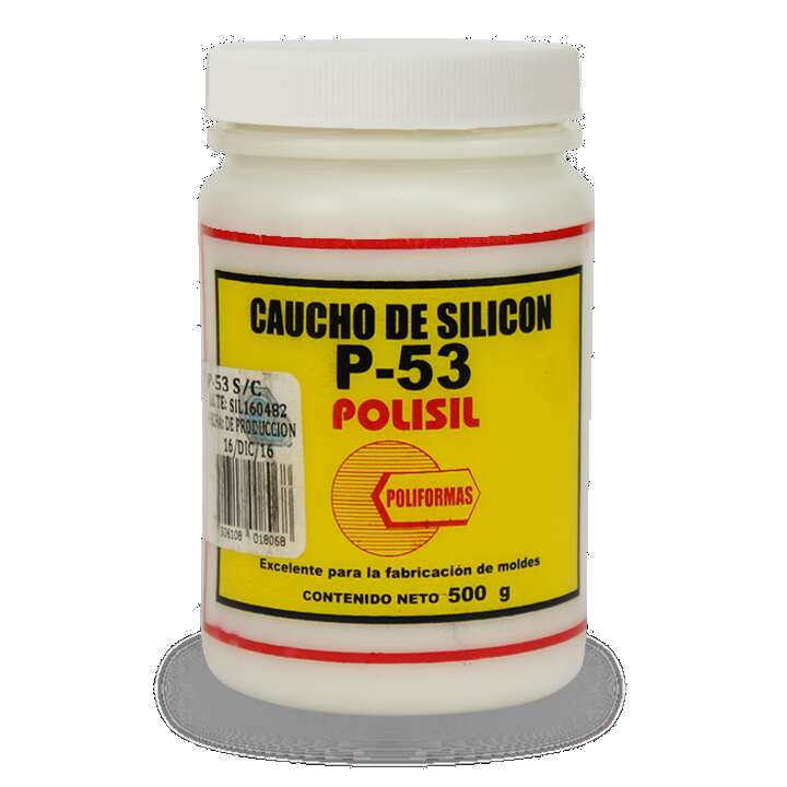 It is a vulcanizable silicone liquid rubber and it is design to create molds used to cast polyester resins, waxes, plaster, and many other.There is no need on using special rooms since it can be cured at room temperature. It is also resistent to high temperatures which can go up to 250° C.
For more information you can read the datasheet here.
It is used with the catalyst TP for curing the silicone at room temperature. The catalyst is liquid and it has a reaction system by condensation.
It is a vulcanizable silicone liquid rubber and it is design to create molds used to cast polyester resins, waxes, plaster, and many other.There is no need on using special rooms since it can be cured at room temperature. It is also resistent to high temperatures which can go up to 250° C.
For more information you can read the datasheet here.
It is used with the catalyst TP for curing the silicone at room temperature. The catalyst is liquid and it has a reaction system by condensation.
- Resin PP-70x60
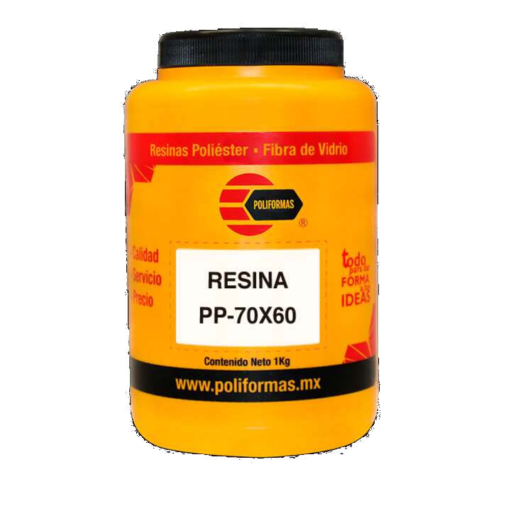 It is an unsaturated polyestes resin with an pre-accelerated averga reactivity. It has a fast curing even in thin section. The curing time can go up to 2 hours depending on the temperature of the room where the casting is been made. It has a good acceptance of mineral charges and it is also has a good barcol hardness development. The best part of this resin is that it do not need a diluent since the formula already contain the diluent and can be applied inmmediatly with the catalyst.
For more information you can read the datasheet here.
The catalyst is the K-200 and it is used to cure at room temperature of unsaturated polyester resins and gel coat's.
It is an unsaturated polyestes resin with an pre-accelerated averga reactivity. It has a fast curing even in thin section. The curing time can go up to 2 hours depending on the temperature of the room where the casting is been made. It has a good acceptance of mineral charges and it is also has a good barcol hardness development. The best part of this resin is that it do not need a diluent since the formula already contain the diluent and can be applied inmmediatly with the catalyst.
For more information you can read the datasheet here.
The catalyst is the K-200 and it is used to cure at room temperature of unsaturated polyester resins and gel coat's.
Designing a mold
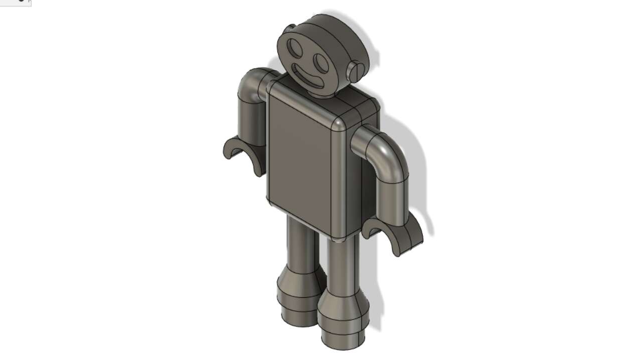
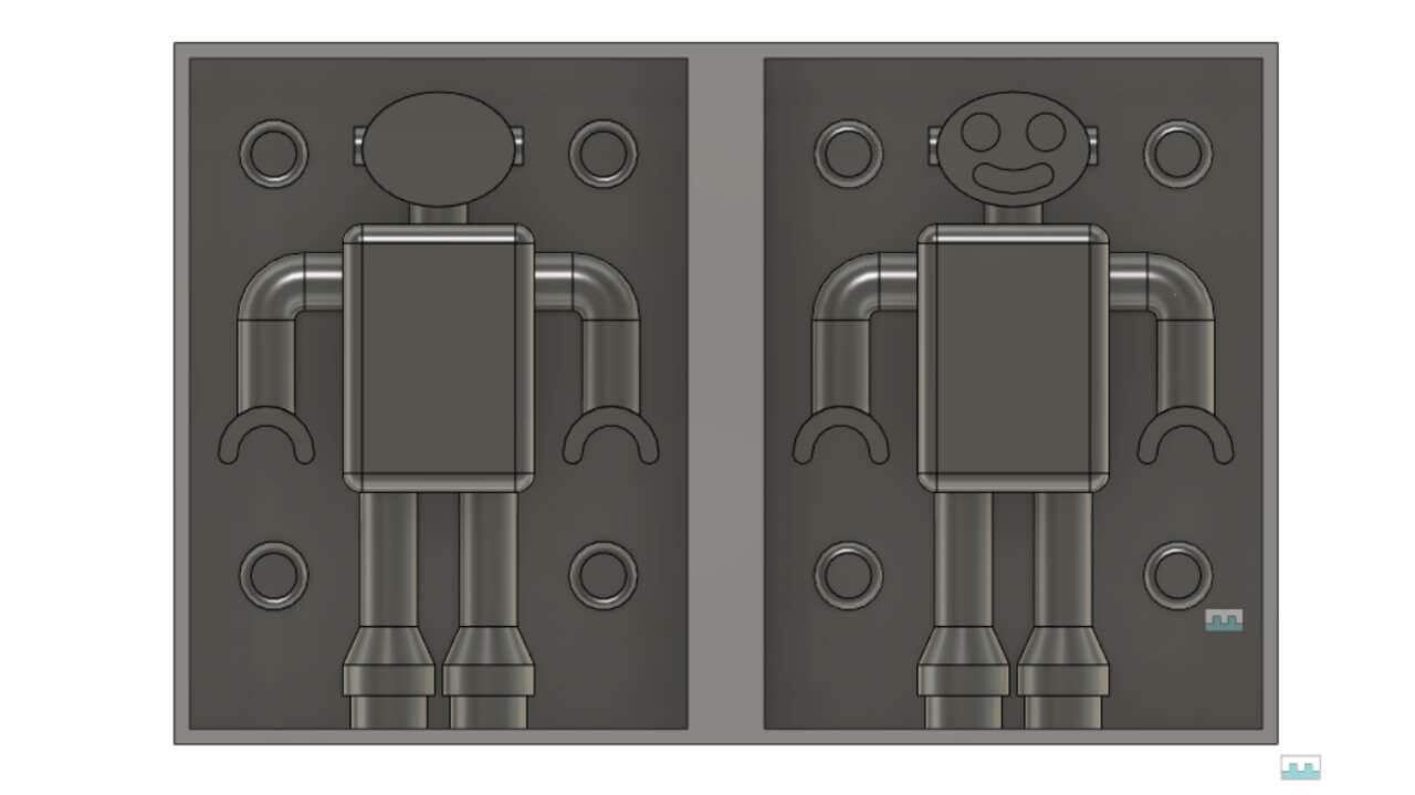
At the beginning I did not know what to do. But later I through that I could create a small robot with geometric shapes to make easier the machining process. Thus, I used Fusion 360 to create the following robot which I would say it looks pretty cool.
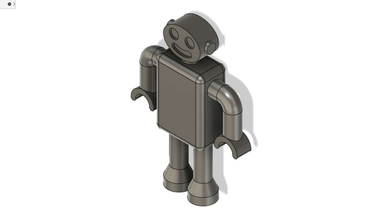
After the figure was created, I used a vertical plane to cut the robot in half. As can be seen in the following picture. Once I split the robot, I created two parts using boolean operation with rectangles. Later I created four pins each per corner to place both parts of the mold in the right position.
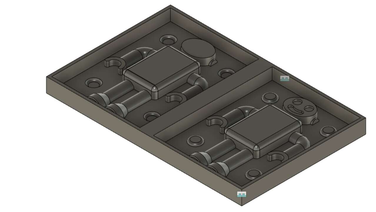
Since, I created both parts with different rectangles, I had to make a union between both parts to get the whole mold and be able to send it in one file to the CNC machine. When I finish the design of the final mold, I exported the design in a STL format so the software can read it. I wanted to share that there is a easy way to create an stl file from objects or components in Fusion 360. You can simply click in File -> 3D print and select the components or object you want to export to STL.
Generating G-Code
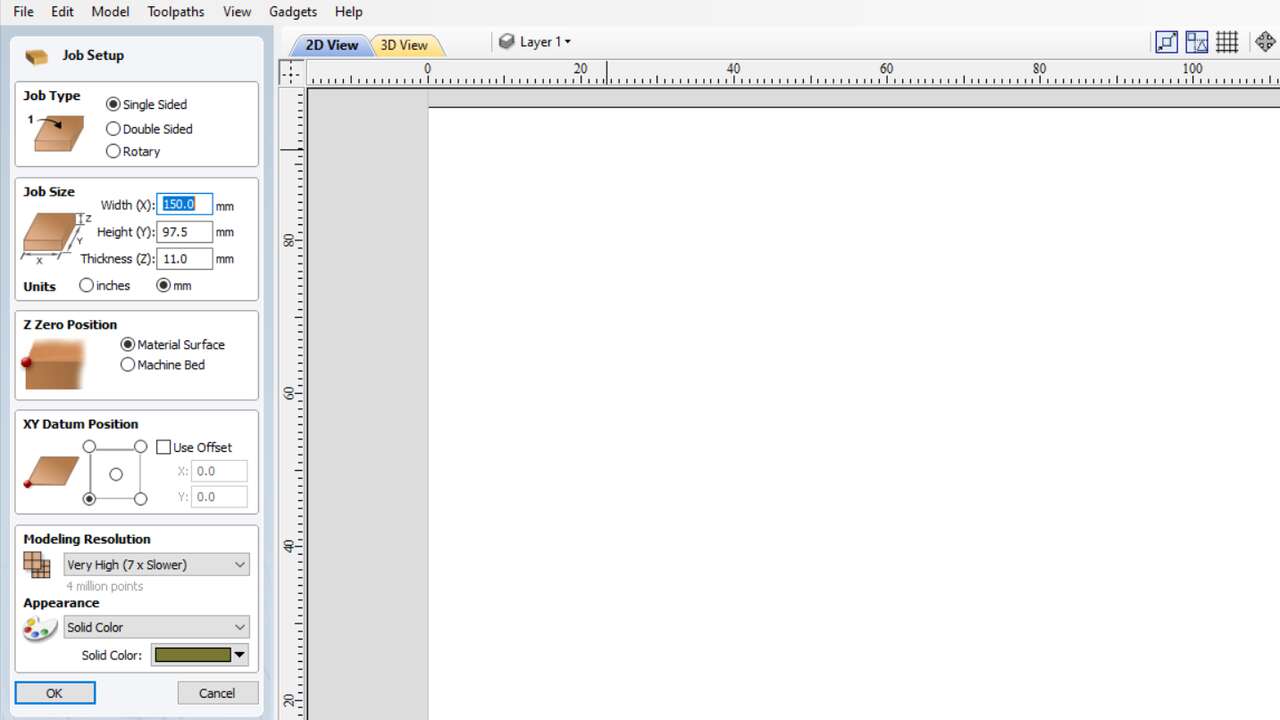
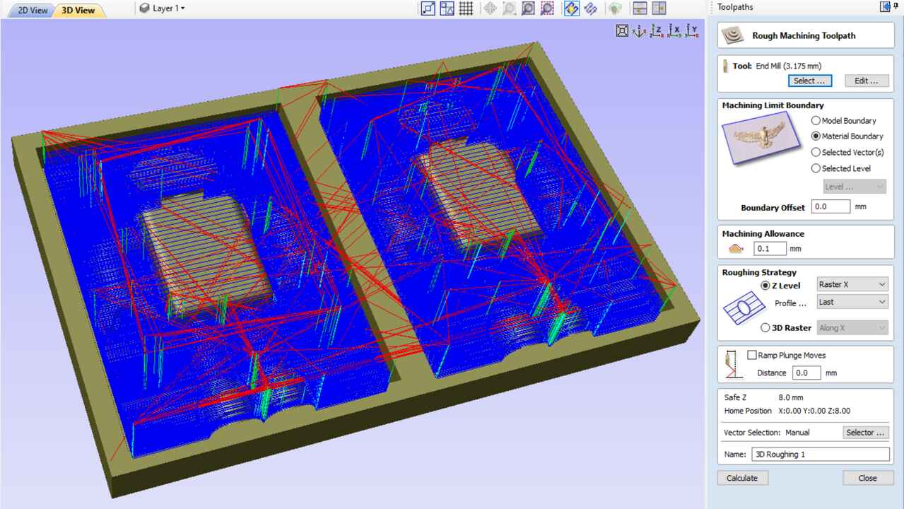
In order to create the G-code, I used VCarve Pro to create it. First, I started a new file where I select the right dimensions of my wood block. Here there are two important parts, The Z zero position must be in Material Surface and the XY datum Position you must select the bottom-left corner.
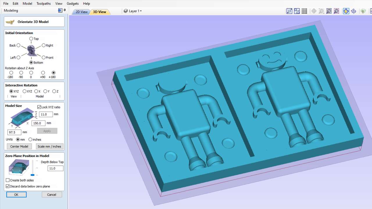
Later, I imported the stl file by clicking in Model -> Import 3D model and selecting the STL file. When the file is uploaded, you have to use the buttons to arrange the STL file in the center of the material block. Again, there is one thing that is important, in Zero plane position in model the Depth below Top must have 0 in order to have the whole model in the software.
For the finishing path, It was almost the same with the difference that I used an ball endmill of 2.5 mm. The feed rate, the stepover, the machining limit and the machining strategy were the same as before. Both path settings can be appreciated in the following pictures.
For the finishing path, It was almost the same with the difference that I used an ball endmill of 2.5 mm. The feed rate, the stepover, the machining limit and the machining strategy were the same as before. Both path settings can be appreciated in the following pictures.
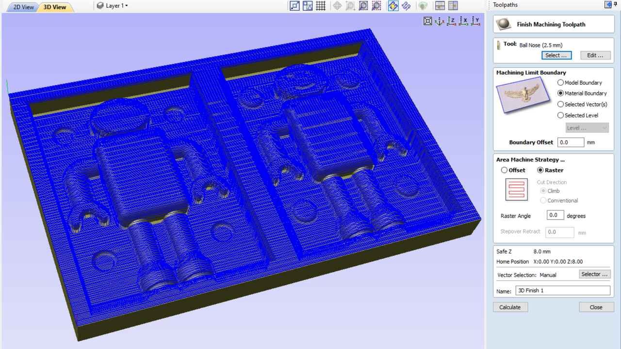
Finally, to save the path I had to change the post-processor for the X-Carve (mm)(*.gcode) which is the post-processor that the Mini Router CNC 3018 PRO accepts.
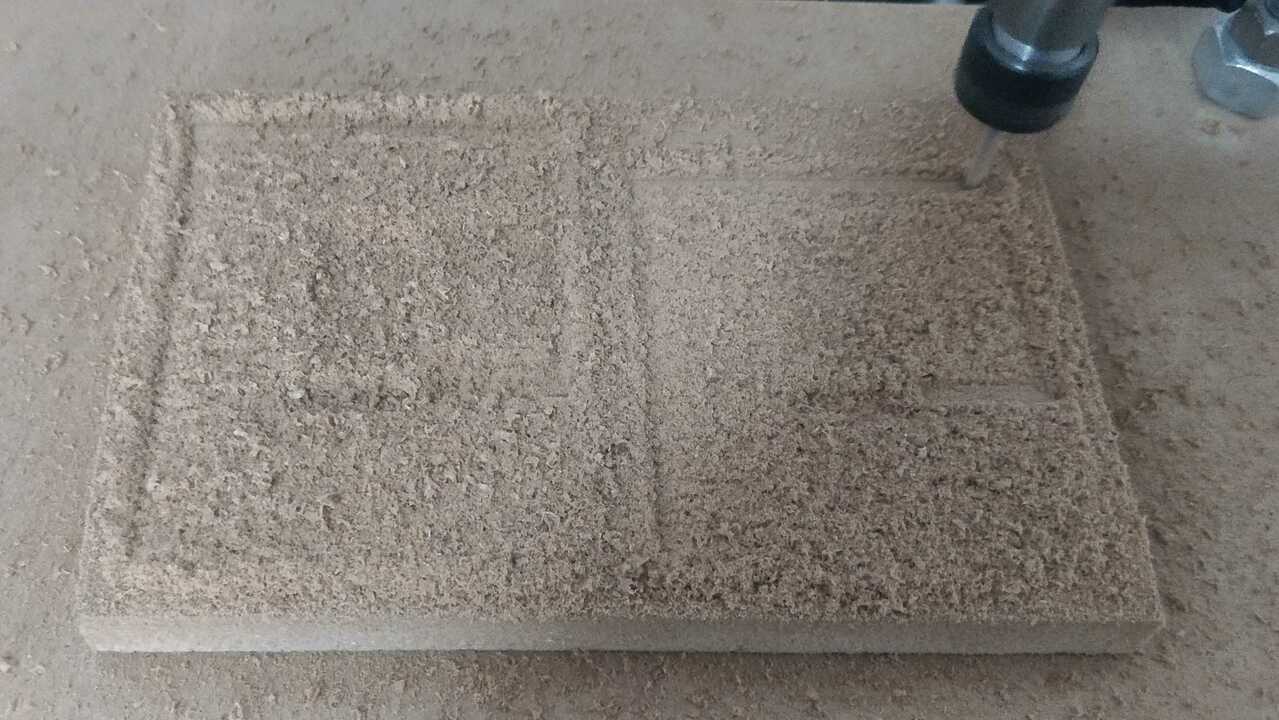
3D Machinning
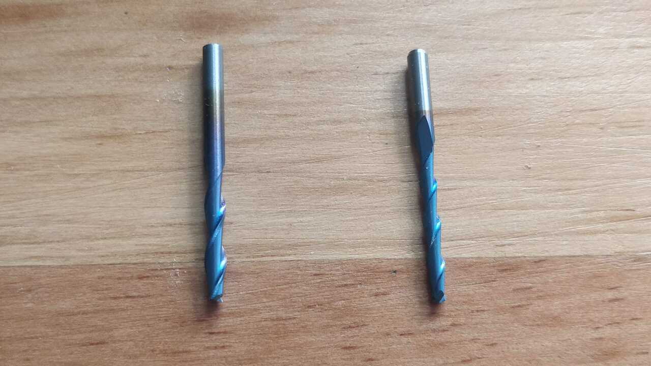
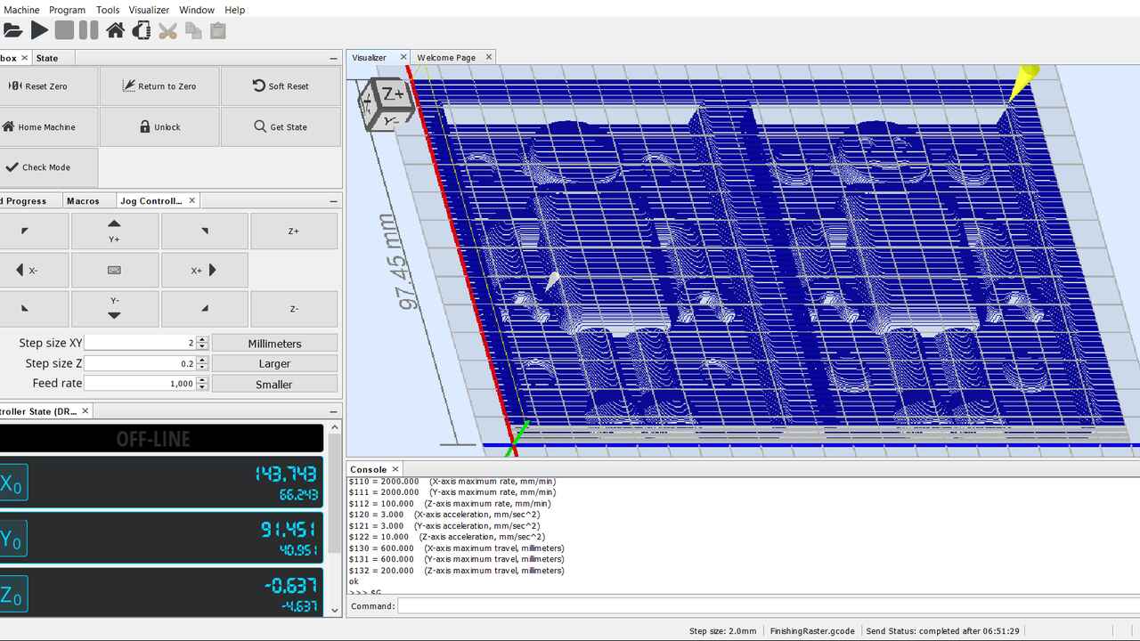
For this practice, I used again the Mini Router CNC 3018 PRO which is a small CNC but really powerfull. I bought a straight endmill of 1/8" and a ball mill of 2.5 mm since it was the easiest end mills to buy near my place. The following picture shows both endmill and the second pictures shows the G-code imported to UGS which is the software that I used to mill in the CNC.
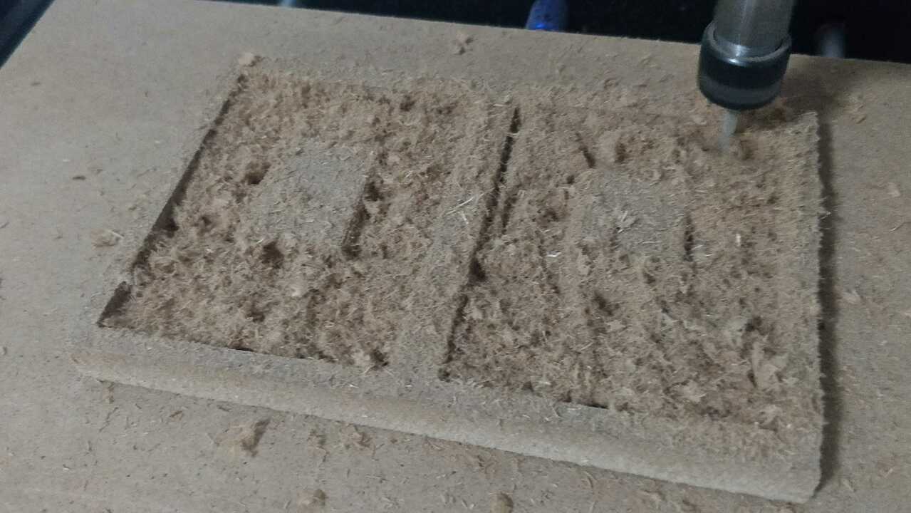
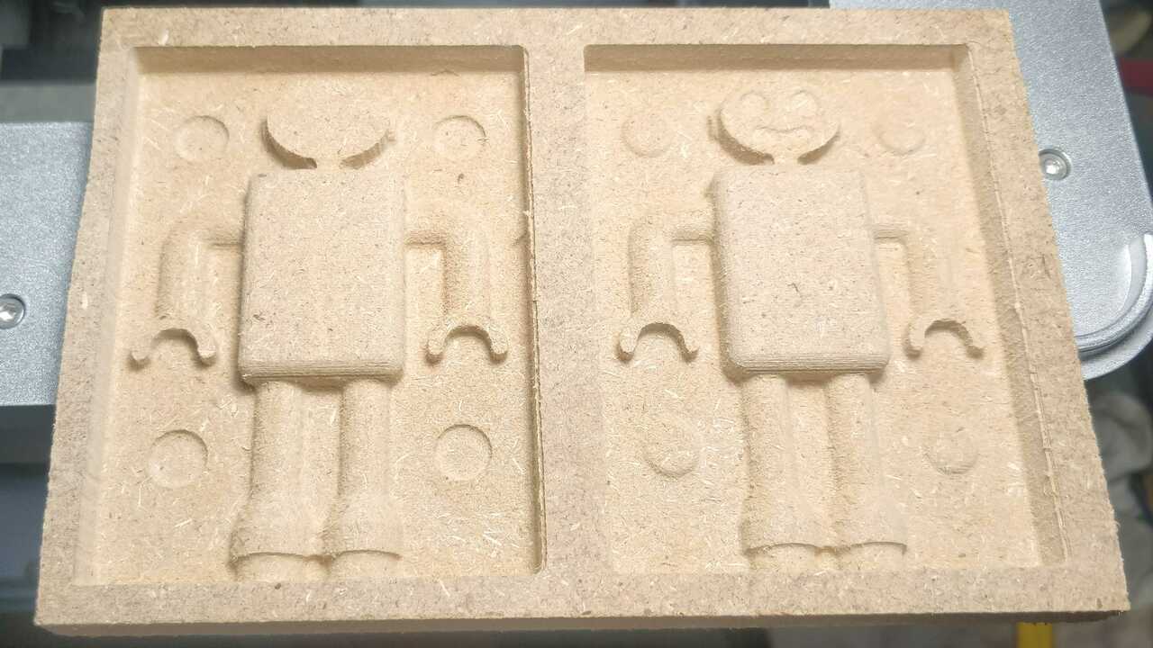
The following pictures depict the machining process of my mold in MDF. It was many hours of machining process since the machine does not have the capabilities to go faster or to cut more material per pass. Nevertheless, I managed to created the whole mold.
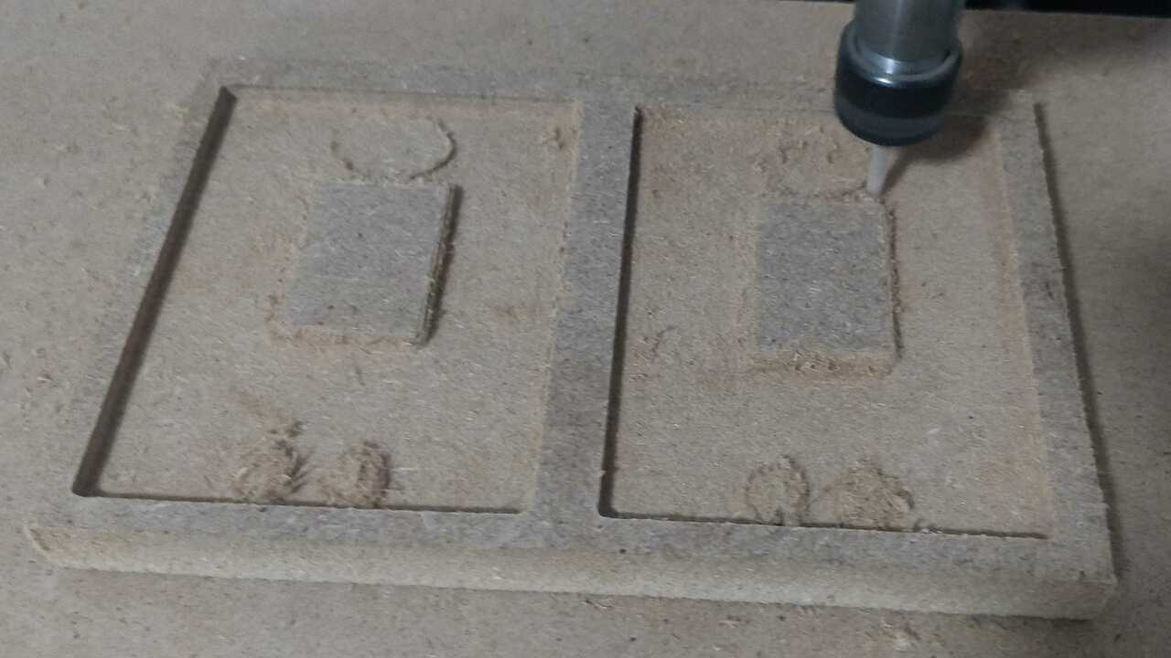
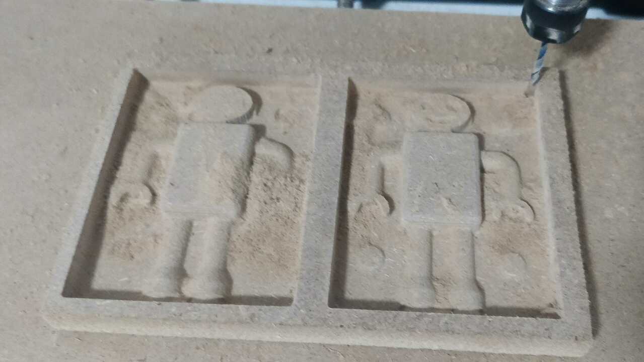
The next figure is showing the final product of the mold and it looks pretty good for a small machine like the one that I have at home.
Silicone mold
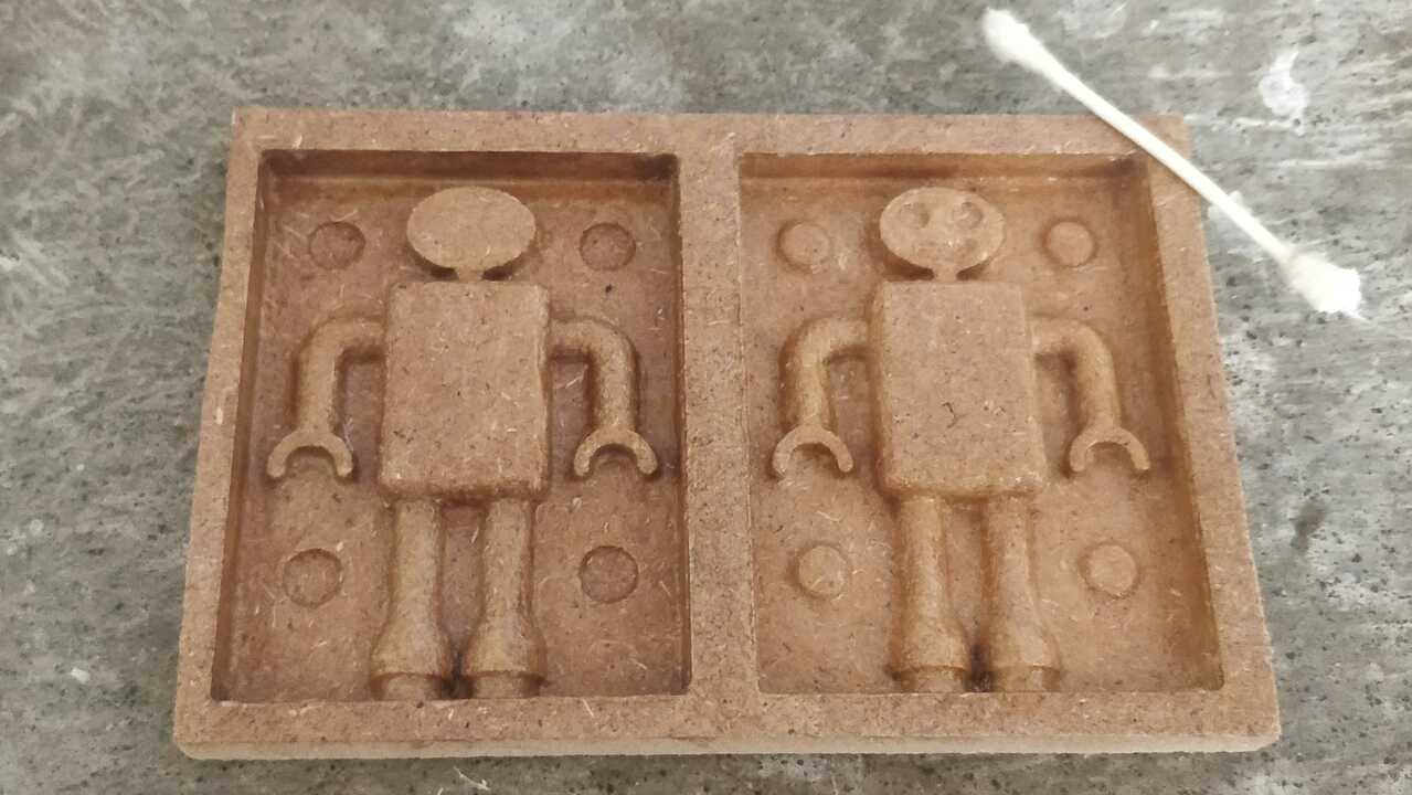
Before I started the preparation for the silicone, I cover the mold with varnish to seal the mold and avoid the porosity of the material. I used an standard varnish for wood. Later, I also cover the mold with vaseline to avoid that the silicone would stick to the wood mold, as can be seen in the following picture.
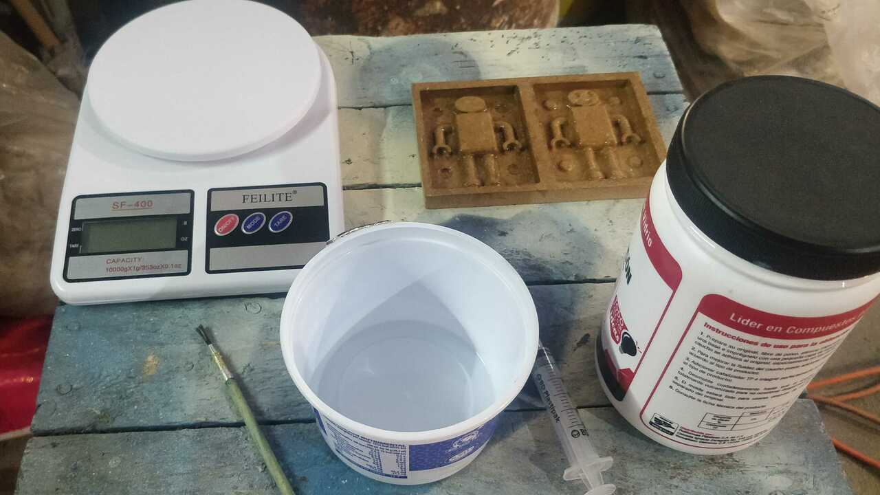
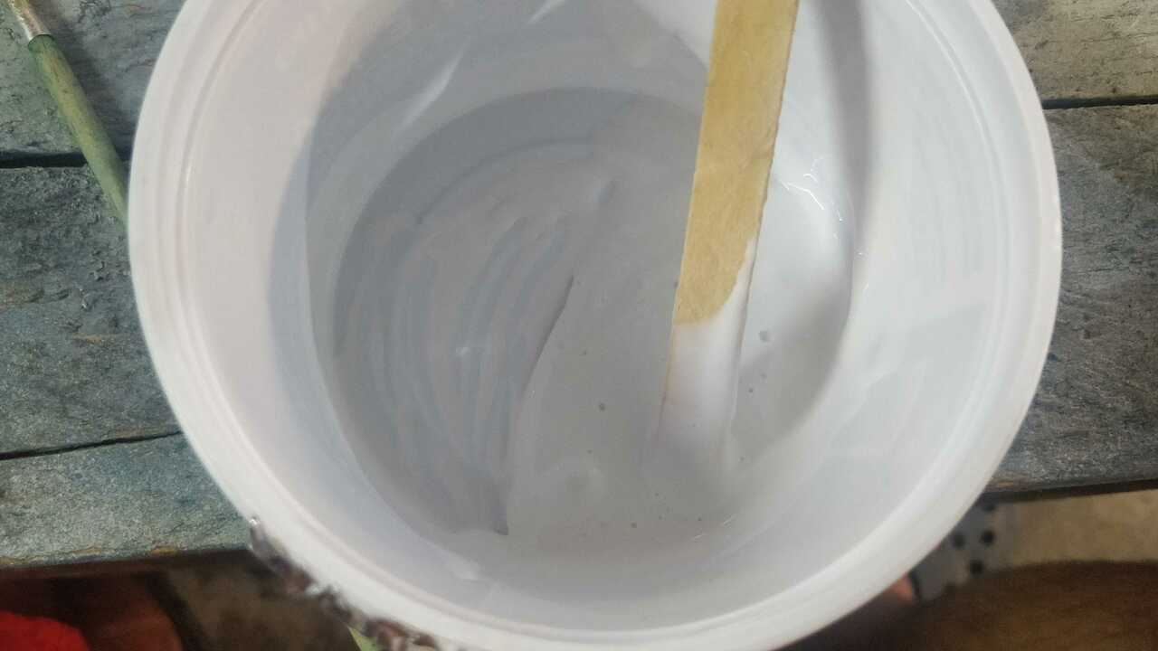
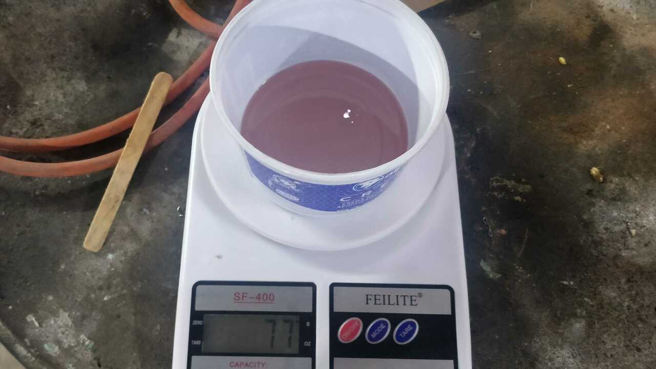
With everything set, I put togheter all the components that I used, which are: a balance, the mold, a recipient, a small brush, the silicone and the catalyst.
After weighting the silicone, I poured it in the recipient and I added the catalyst. It is important to mix both components really well. I did exterior circles in one direction and interior circles in the opposite direction to mix it. When the mixture looked good, I used the small brush to cover all the parts that could created a problem for the air that could be trapped inside the silicone.
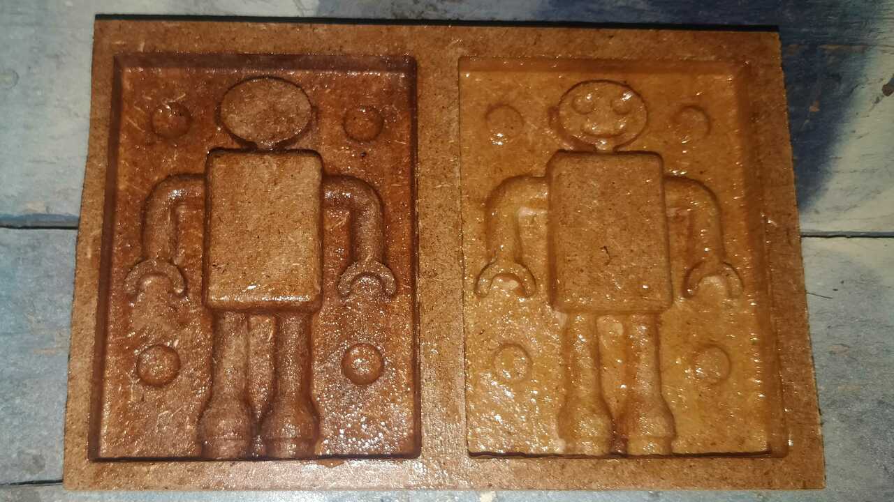
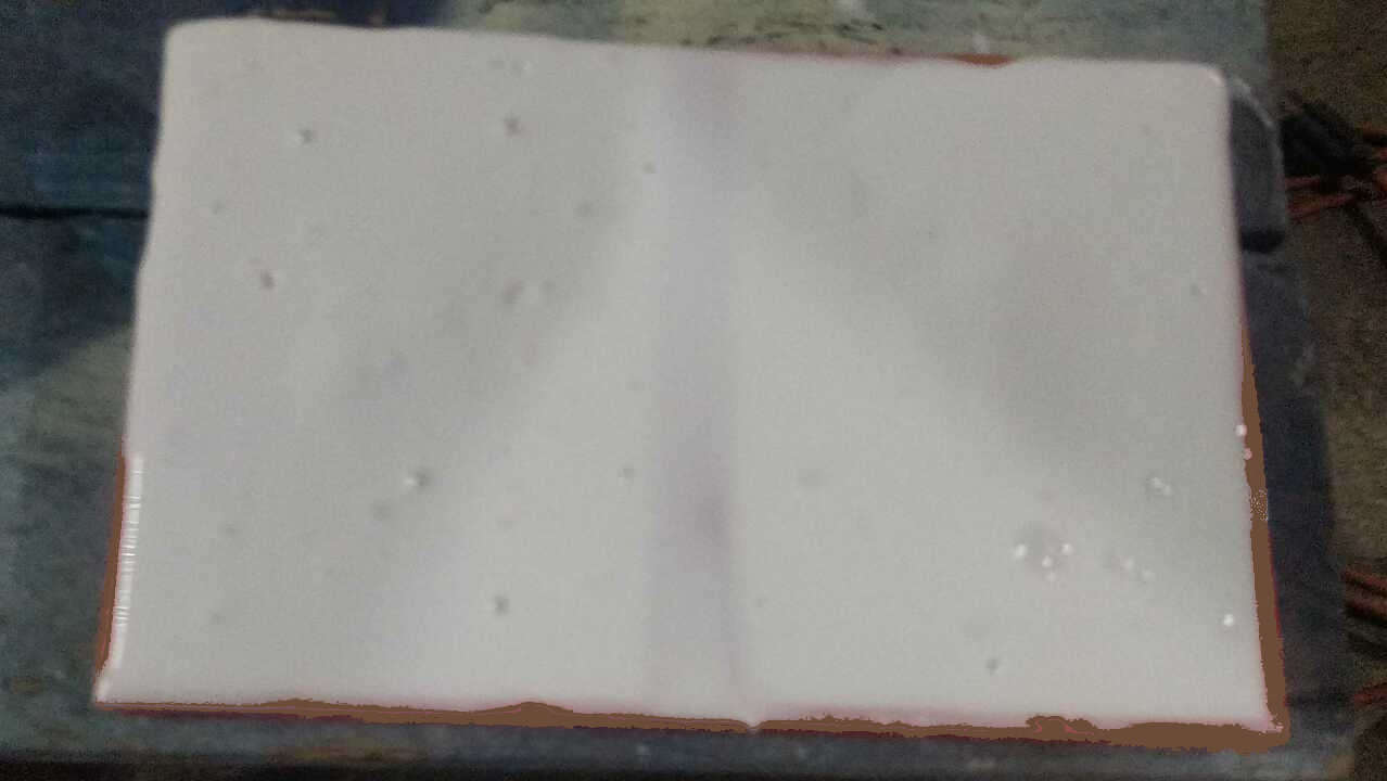
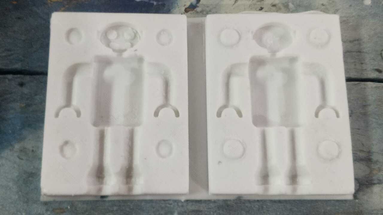
When I finished with the first layer of silicone, I poured the rest of the silicone into the mold and wait for 6 hours to cure. After that time, I was so nervous that I did not want to remove the mold but surprisingly the mold looked perfect as can be seen in the picture. It was my first time doing it and I thinked I nailed it.
Casting
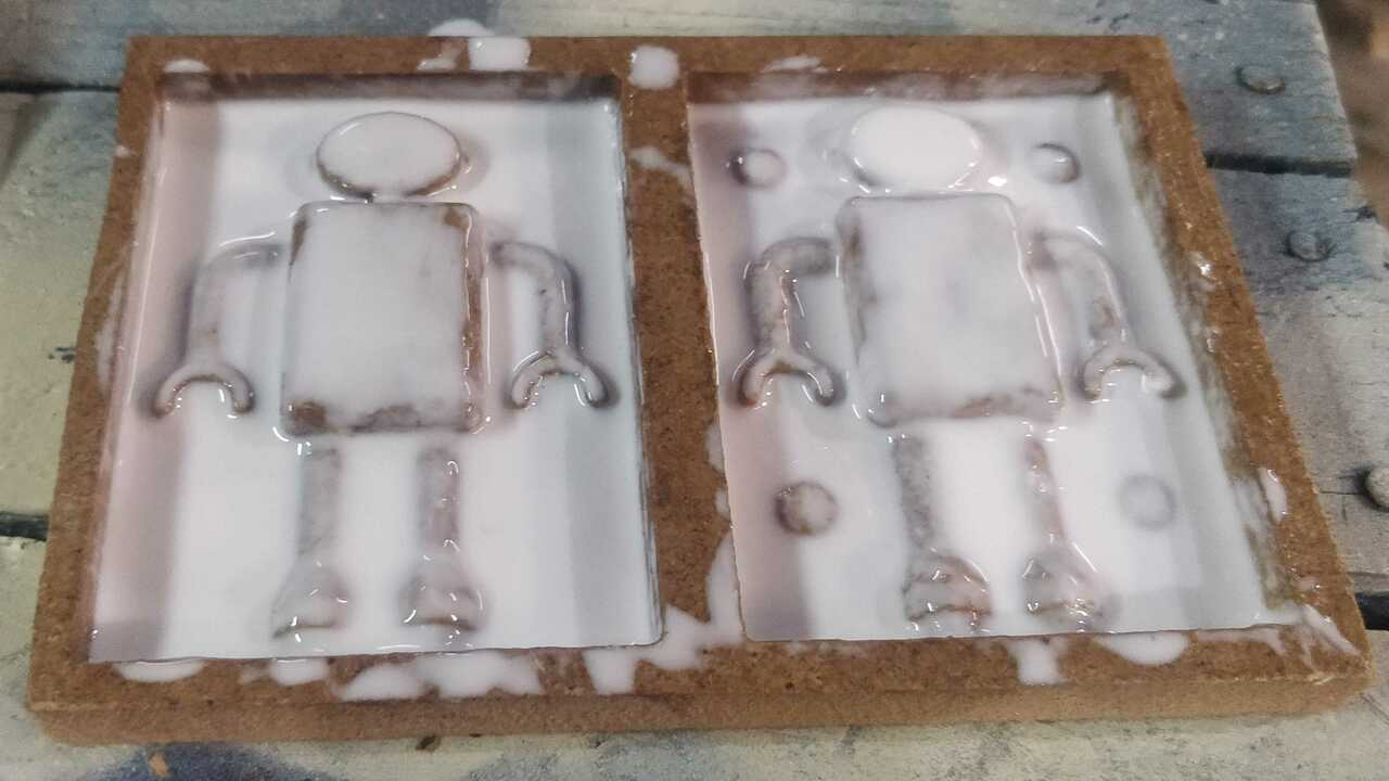
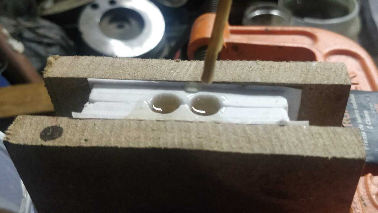
For the casting, I put both sides of the mold togheter and I used two C-clamps to hold them and avoid any weird movement during the casting. When I had everything ready, I measure the required resin and I put the catalyst to mix it really well with the same process as the silicone.
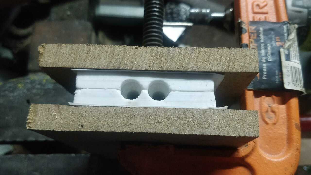
To pour the resin, I used a small wood stick to pour it. Since the holes are not so big and I would say the pouring process it was a lot easier than I expected with the stick. Highly recommendable.
After an hour, I went to verify that the resin had completely cured. And yes, it was solidified but I was really sad to see that the arms of the robot were not done because I did not let veins for the air to scape. Thus, the mold generated a vacuum in the arms and that is why the resin did not enter there.
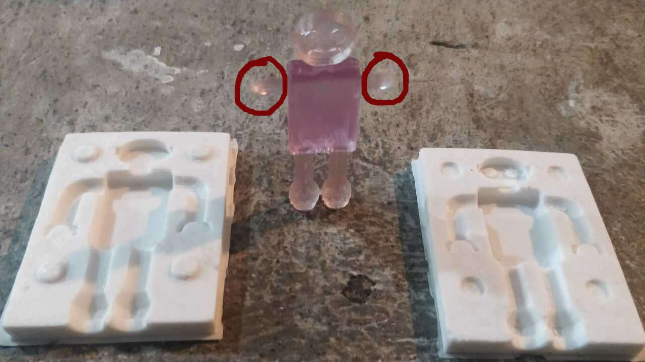
So, I decided to manualy create two exits for the material at the end of both hands but again the opposite finger were not done because a small vacuum was created there.
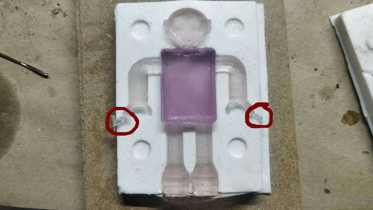
Thus, I create another veins but this time to connect the other fingers with the main body. And finally, the piece was done as expected the first time.
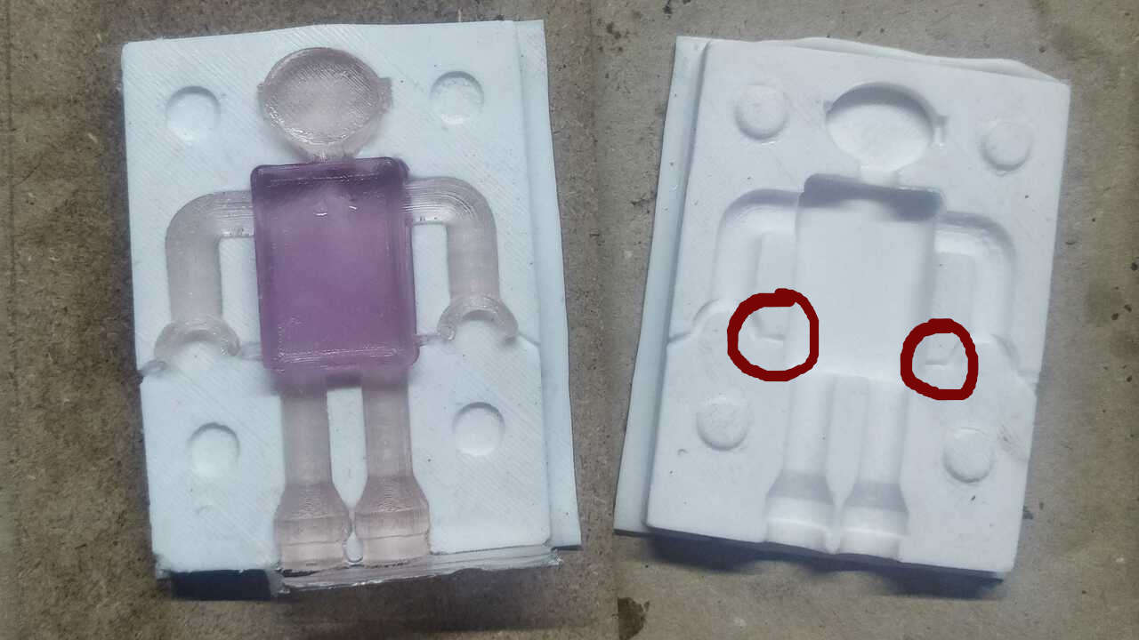
Please remember to verify that there are no parts of the mold where vacuums can be created. When I was designing, I though everything was right untill my first piece was created. Then, be careful and pay attention if you do not want to wast material.
Files created
Useful Resources