Mechanical design
For the mechanical design week, we have a first conversation as a team about the posiblities of the project and we decided that we can create a drawing machine but we did not know about what type of mechanics can be the best. Thus, we did a benchmarking to see multiple examples like the following:
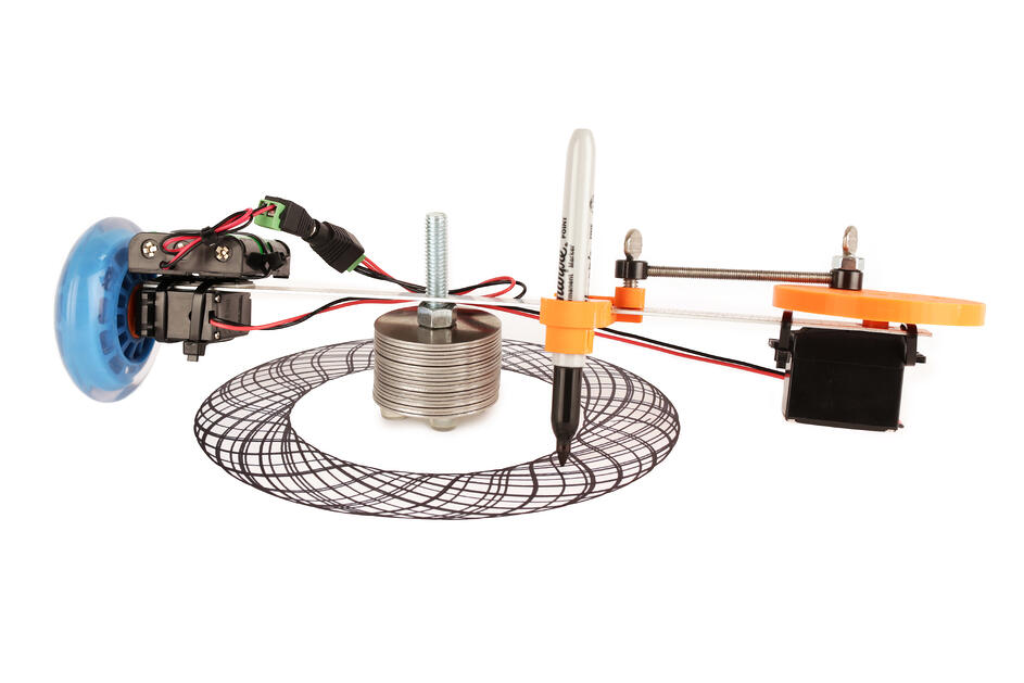
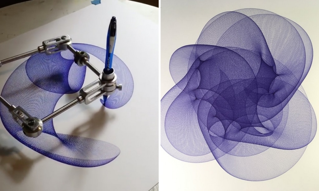
The two previous machines are machines that can draw pretty awesome. The first machine is a Torus drawing machine that can be found in tinkercad and the second is an spirograph developed by James Nolan Gandhi
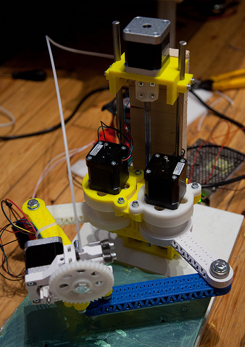
After searching more in the internet I found a 3D printer that uses something really similar to what I was thinking to do, the machine use 4 servomotors, two for the movement in x and y, one for the movement in z and the last one to push the filament, the machine can be seen below:
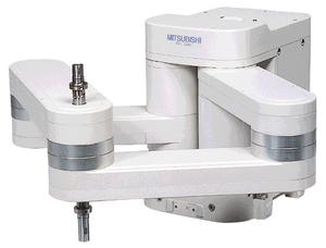
Another great example that was used as a reference was the RP-5AH Scara robot develop by Mitsubishi and which is shown next:
Until this point, we can say that it was a team work and the team was composed by a few students from Colombia and me from Mexico. But they were having troubles accesing the FabLab and I told them that I would create the whole mechanical structure since I have access to a few machines and I can easily buy the required items.
Designing and Machining
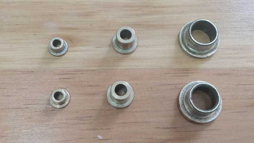
I used the previous examples to imagine how the ScaraGraph will end up. But first I searched for the dimension of the servomotors and the bushing, because depending on those dimension is the dimension of each link. My grandfather had a workshop where he fixed motors and he had a bos full of bushing where I found the following items:
The bushing that I found have an internal diameter of 4, 6 and 11.5 mm. Thus, I decided to use the biggest ones to be able to hold a pencil in the center of one and to pass a bolt trhough the other and stablish a perfect joint between links. The motors that were chosen are the Nema 17 since thery are the ones thar provide the most torque in its range and they are not so big. The most important about the motors is that their shaft has a diameter of 6 mm.
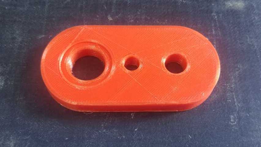
Thus, I created a testing link to see how the bushings will fit into the links and also to analyze if the pressure apply by the tolerance that I used it was engough to hold the bushings. The following picture shows the testing link where I test two time different sizes until I got the right one.
Once, I found the best diameter for the bushing on the links. I proceed to create the two required links. I took into consideration that at the beginning of the links I would place a motor and I decide to put an octagon in that part, so later on I can create a couple for the motors. Regarding the links. I try to save the material and I created a type of structures link with holes in multiples places.
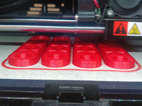
When the design was done, I proceed to 3D print the four arms that are needed as teh following picture shows. It took me a while to get these links, maybe aorund 5 hours to be completed.
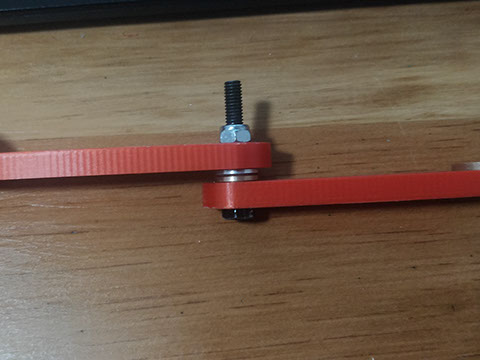
Now is time to use a 6 mm x 1" bolts with security nuts to create a joint and avoid that the nut will move when the link rotates. The joint must be seen like the followign picture:
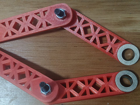
After I verified that the joint was working correctly, I proceed to join the next two links and I fell really happy to see that the idea is becoming real.
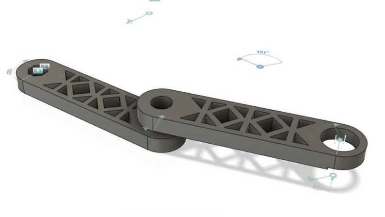
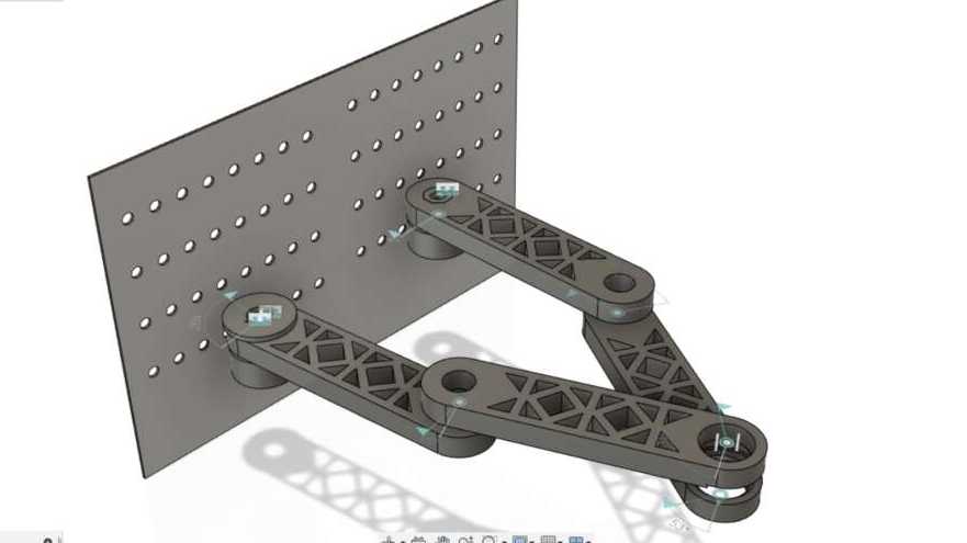
Since I already knew the dimensin of the shaft and the dimension of the pencil. I created the rest of the components to be 3D printed and/or machined. The following picture shows the final design in Fusion 360.
The followign video shows a smal video clip about the designing process that I developed when I was iteration, changuing and modifying the files.
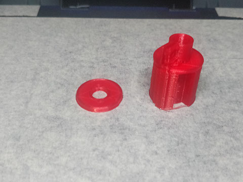
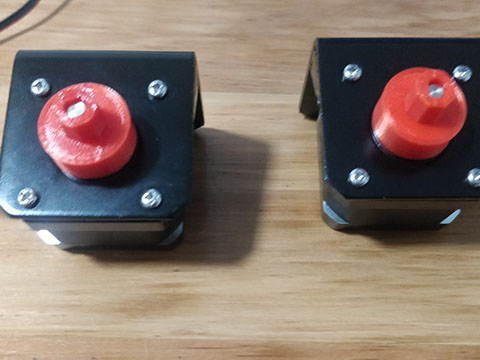
So, i 3D printed the couples for the motor shafts and also the pencil holder. Both of these pieces can be seen in the following pictures where it can be appreciated that the coupler ends wiht an octagon to fit into the links and avoid any slippage.
Now, it is time to create the back plate which has multiples holes to be able to adjust the motors and modify the capabilities of the machine just by changuing a couple of bolts. So, I used a Minimill for PCB to cut a the pattern in a MDF even if the final plate is a Polypropylene. I did it in MDF because I do not have an endmil for plastic and if I do not use the right one is possible that the endmil gets stuck and break while cutting.
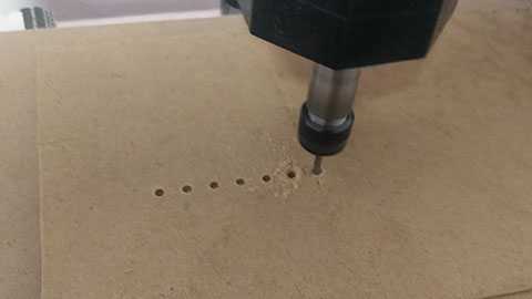
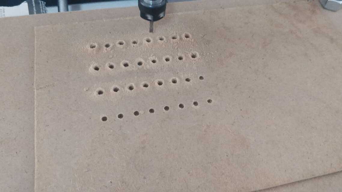
When the machining was done, I used the MDF plate as a pattern to drill the holes into the polypropylene sheets. I used polypropylene because it is plastic which has the capacbilities to support the machine while avoiding any flexion or any other damages.
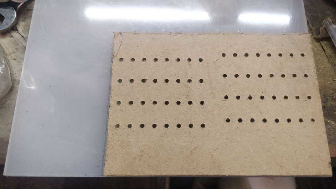
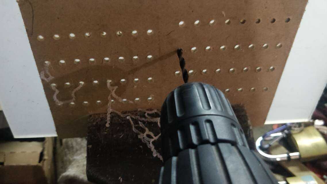
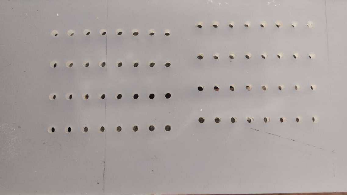
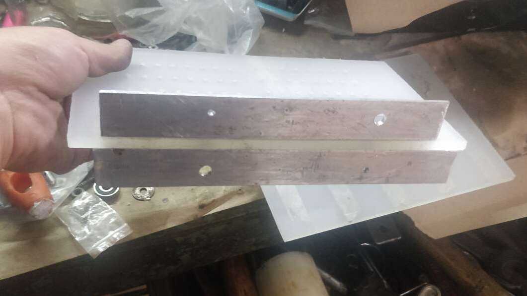
The final plate is shown below and it can be seen that even when I was not able to do it with the Minimill, the pattern worked perfectly to create the required holes. Now it is time to put two aluminium profiles of 1/2" to hold the back plate with the base. i did not buy these L profiles but I did created two holes along the profile to go trough the plate and hold it. here I used four bolts to hold two L profile to the bottom of the back plate as the picture shows:
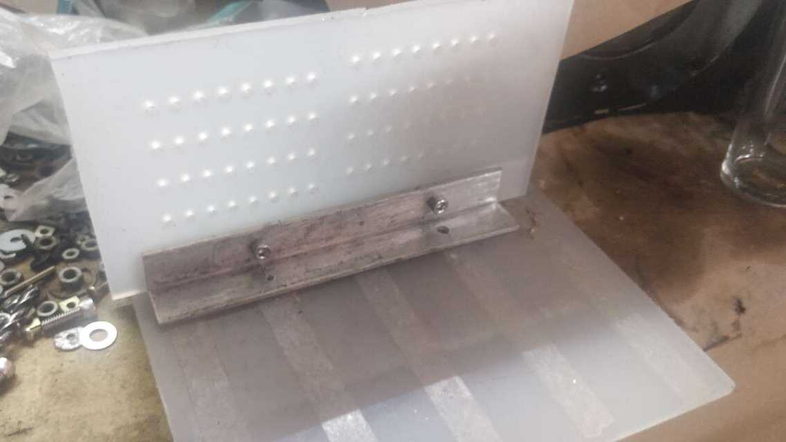
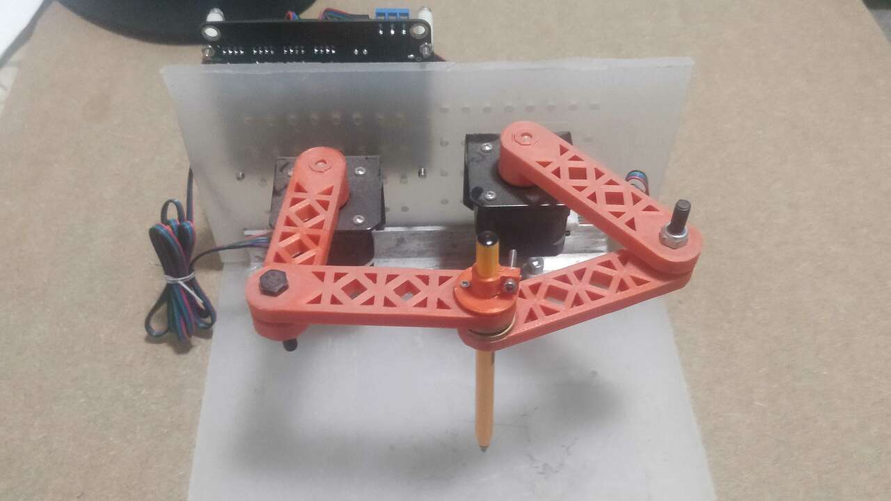
Later, I took the rest of the bolts and hold the back plate with the bottom plate in the same way I did the previous step. In case everyhtin worked perfectly, you must have an similr structure like the one below:
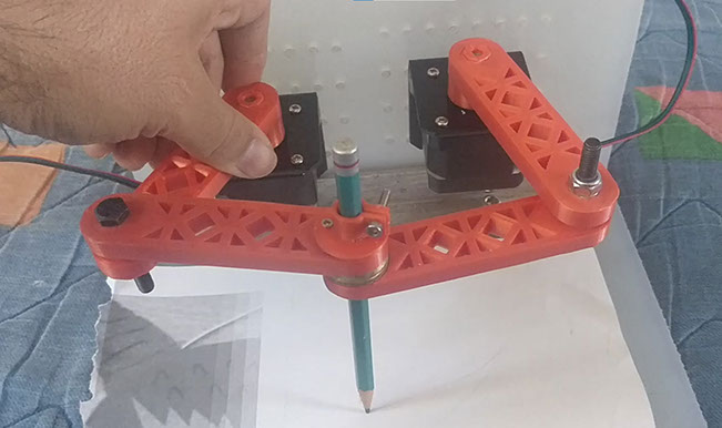
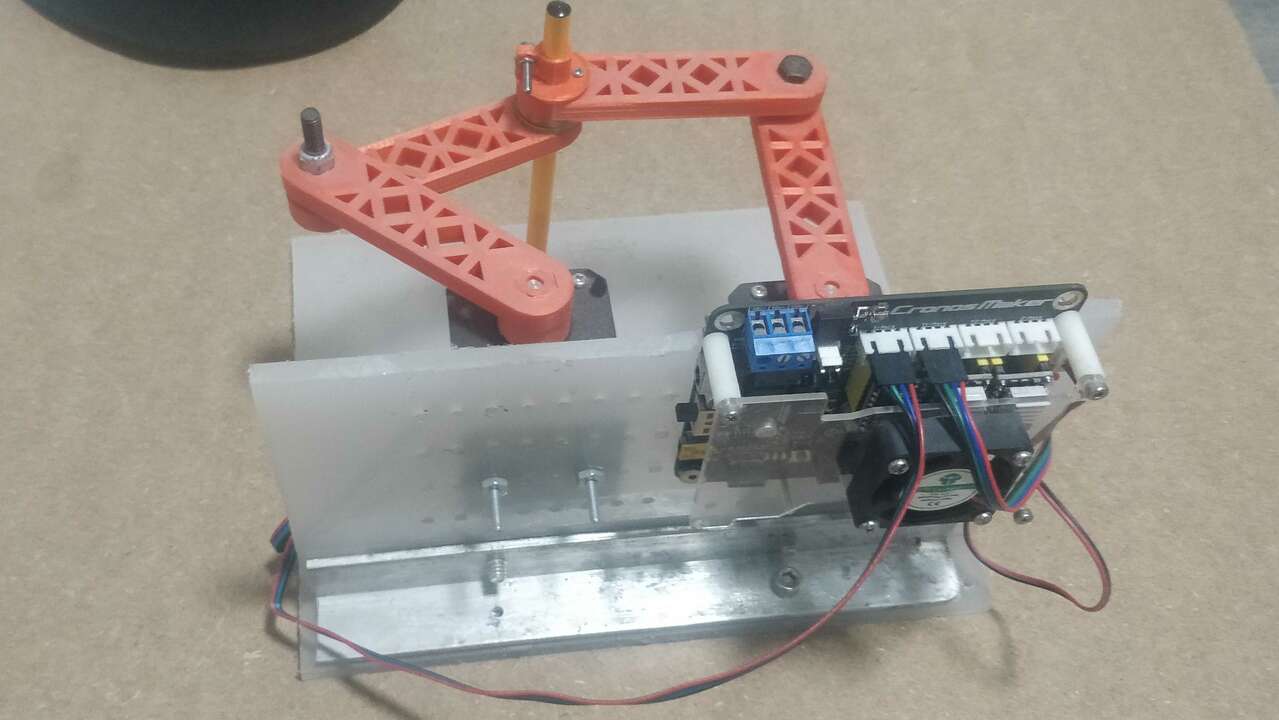
Regarding the motor I simply use the 1/8" bolts with their nuts to hold the motor in place and avoid any movement. For the motor I use two L supports to hold the motor to the back plate and the rest was already created but I added the pencil at the end to see how it wilk look.
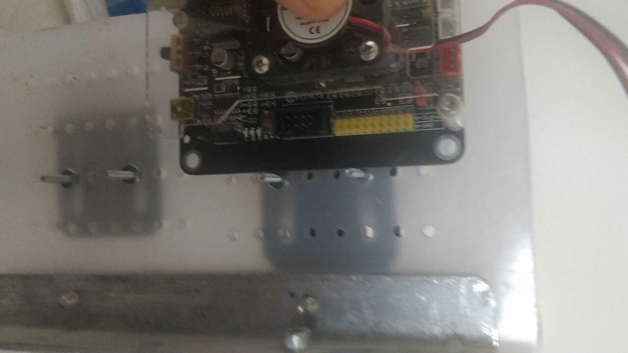
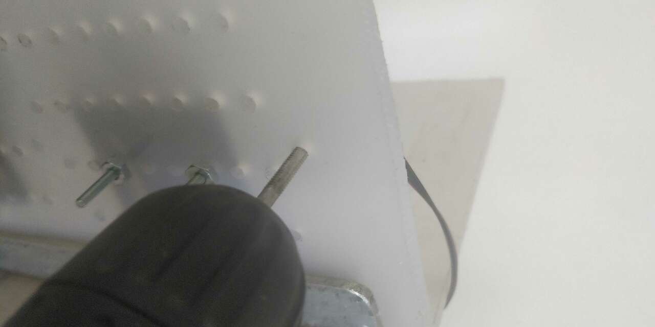
Now, it is time to place the GRBL controller in the back part of the ScaraGraph. Thus, I put the board in the back part and I marked a point in the middle of the holes to hold the board. Later I used a 3 mm drill and a 4mm tap to create a thread and place two 4mm bolts to hold the board. The following picture shows the initial board and the tap process.
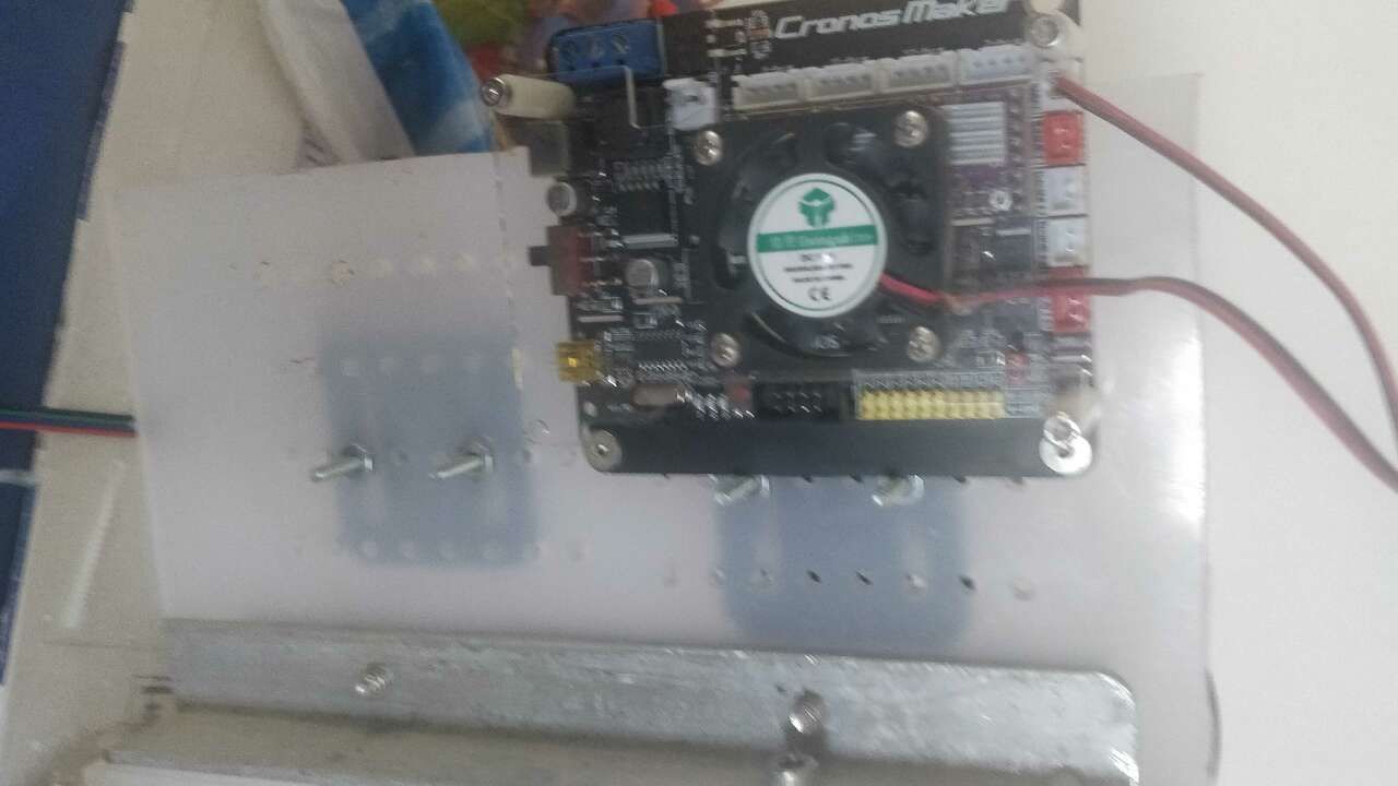
When the thread was done, I put the 4mm bolts and this is the final result.
Finally, the following video shows how the machine is moving manually so we can get an idea about how it will move in the future.
The following table shows the bill of material to create the ScaraGraph.
| Quantity | Component | Model |
|---|---|---|
| 2 | Stepper Motor | Nema 17 - 42BYGH34 |
| 2 | L support | For Nema 17 |
| 2 | Polypropylene sheets | 25 cm x 20 cm |
| 1 | GRBL controller | Cronos Maker |
| 1 | Charger for GRBL controller | 24V / 5A |
| 1 | Mini USB to USB cable | N/A |
| 2 | L profile | 1/2" x 20 cm |
| 8 | Bolts | 1/4" x 1/2" |
| 2 | Bolts | 4mm x 1/2" |
| 8 | Bolts | 1/8" x 1/2" |
| 8 | Nuts | 1/8" |
| 2 | Bolts | 6 mm x 1" |
| 2 | Security nuts | 6 mm |
| 4 | Brass flange bushing | I.D (6mm), O.D(10mm), and Height (8mm) |
| 2 | Brass flange bushing | I.D (9mm), O.D(16mm), and Height (8mm) |
| 1 | Pencil | 7 mm diameter |
| - | Multiples Wires | N/A |
Programming the ScaraGraph
At the end, the other students from Colombia were not able to use their machines. Thus, I decided to finished the machine by myself. To facilate the programming, I used G-code to create a routine in the ScaraGraph and draw an especific pattern. In order to achieve this goal, I had to adjust the parameters in the GRBL controller.
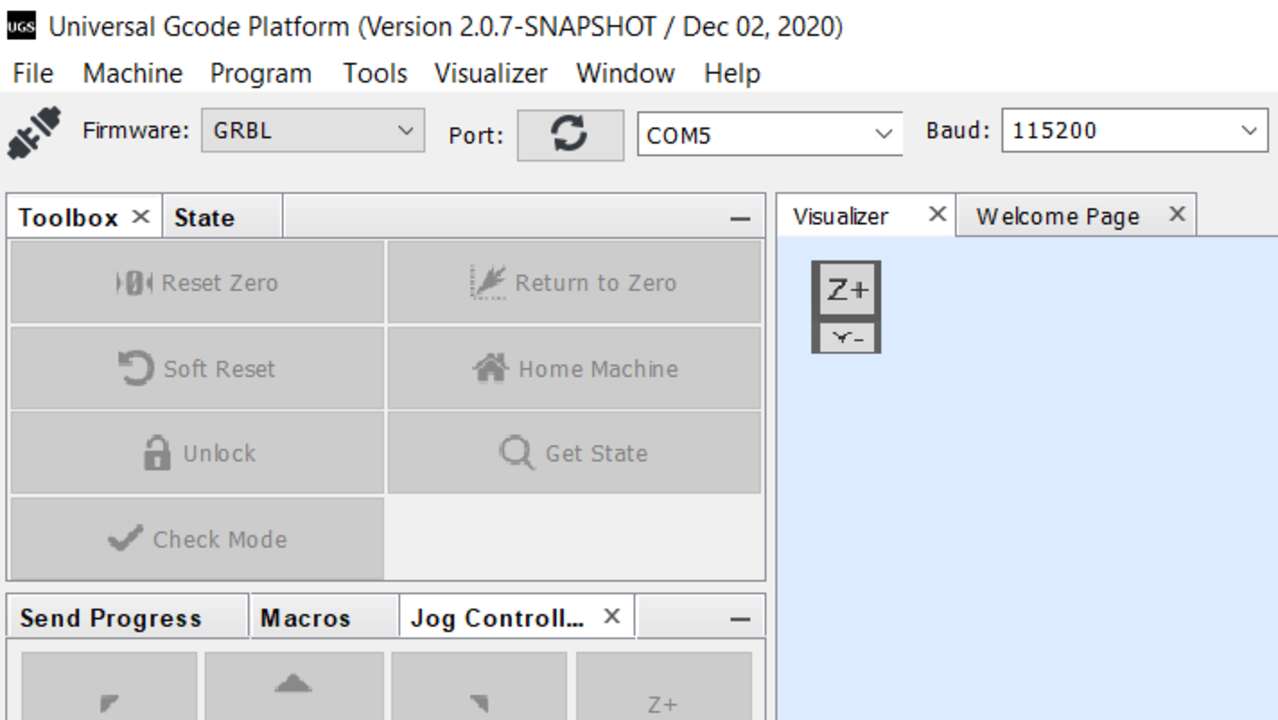
Thus, I used UGS like in the Electronics Production week to obtain the parameter that the board has. The first step is to connect the power supply into the board, later the usb cable to the computer, after we can verify the COM number in the device manager for windows, finally we open the UGS program and we connect the program to the board just by selecting the COM port and click in the top left icon just like the following picture shows:
If the connection was a successful, you will se that in the bottom of the window all the parameters will show up:
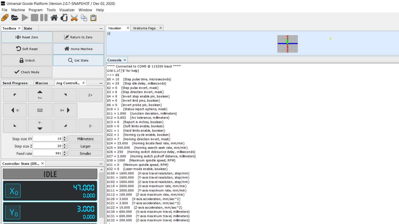
To avoid any possible error, please copy the parameters and save the in a txt file for future reference. In my case I changed the parameters with the following parameters
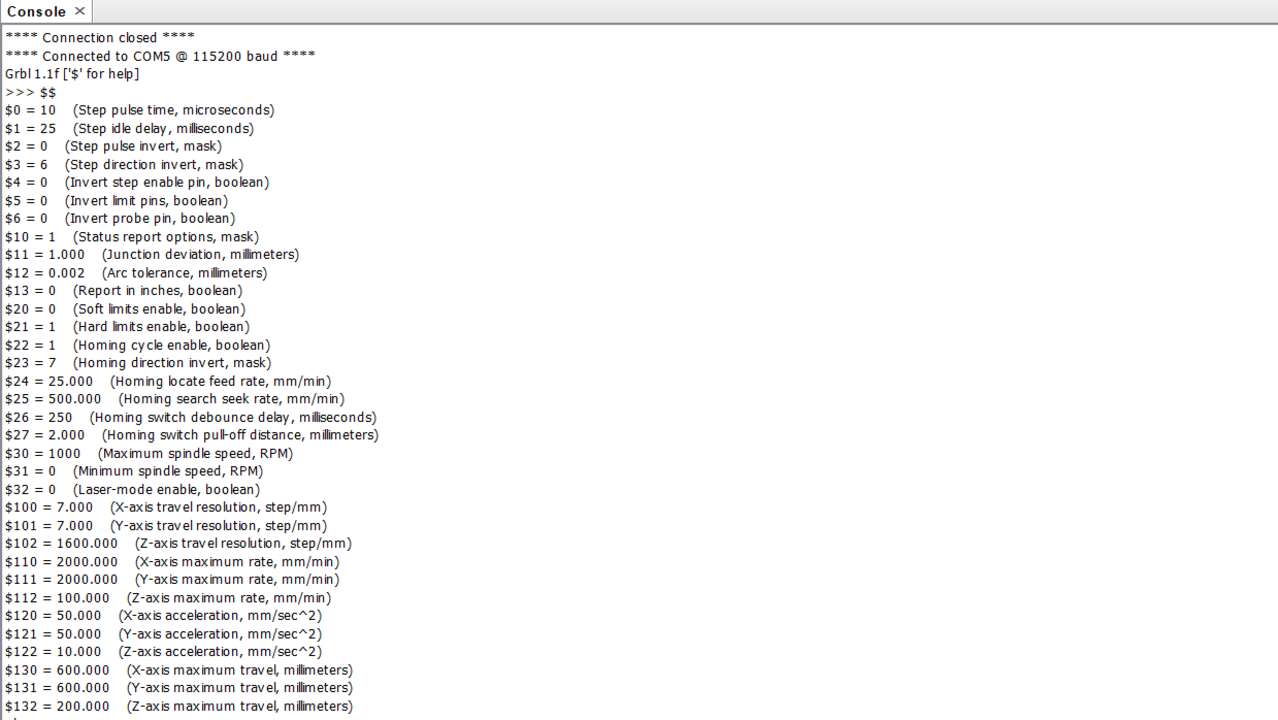
As can be seen, the only parameter that I changed are the x and y resolution and acceleration. To change the parameter you must write the "$" followed by the parameter number later an "=" and finally the new value. An example of changuing the x travel resolution to 7 is below:
$100 = 7
Later I verified that the motors were moving in the right direction by changing the step resolution to 0.01 mm and by clicking in the arrow and see where the motors were moving. The arrows to move and the resolution can be change in the left side panel just like the picture below shows:
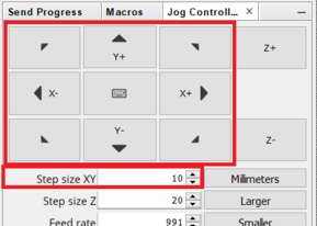
In my machine the motors were reacting in the way that the picture shows where is important to see that the right motor looking from the fron is connected to the X axis while the left motor the the Y axis. Remeber that the GRBL board has the connector with the axis that it moves for easy identification.
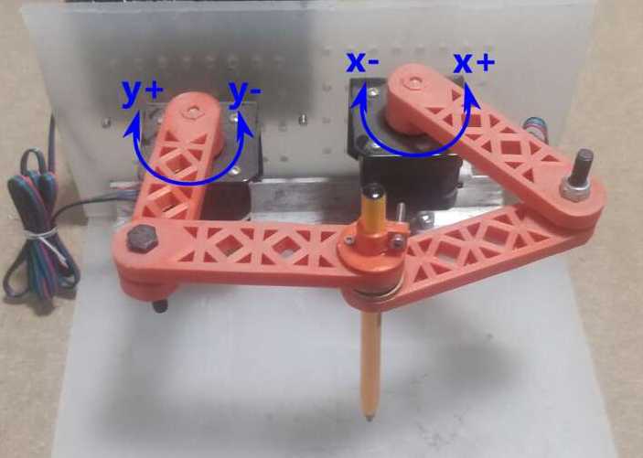
In case that the motors are moving with a diferent axis just change the wire to the right connector. If the case is that they are now moving in the right direction just change the orientation of the connectors. If everything is right it means that the machine setup is done.
After the setup was executed, I created a G-code that basically creates a pattern because it moves the same proportion in both axis with the difference that in one it moves to a differente coordinates every cycle to create a pattern like in the spirograph. The G-code created is shown below:
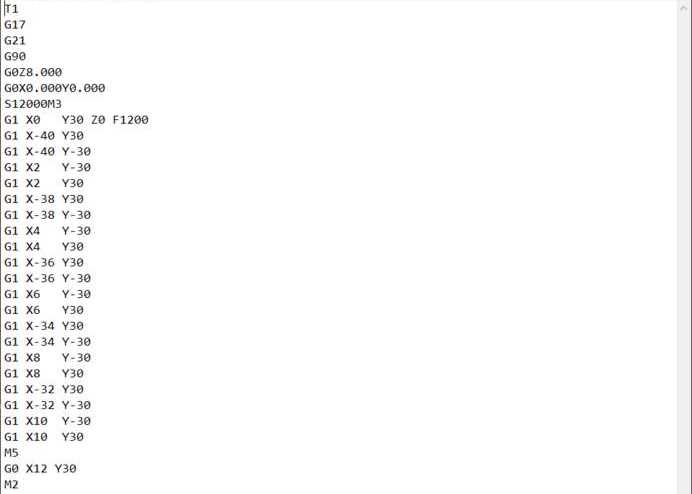
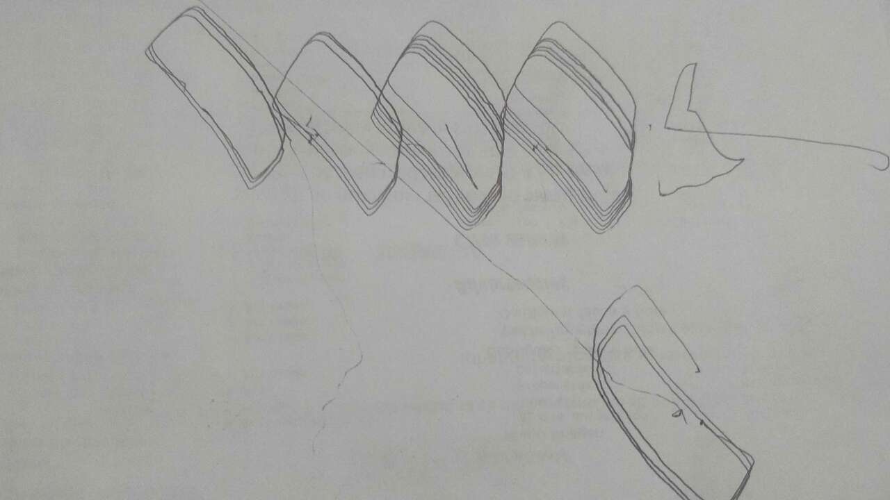
To upload the code you just have to click in the open button in the top-left of the window and select the file where the gcode is saved. In my case I used NotePad and save it with an .gcode extension. Once the code was running I just place a piece of paper and let the machine draw the patter. The next picture shows some pattern that I drew with the machine.
Finally a video that shows how to upload the code, place the paper, send the file is shown below. However, the most important is to see the machine working.
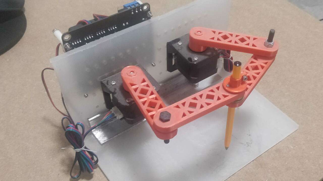
I also placed more pictures of the front, back and side of the machine for a better reference of the final machine
I think I nailed this assignment even if I could not have the help of a team to create the machine. Nevertheless, I think it would have been better if the whole team could have participated.
Files created
Useful Resources