Computer-Controlled Machining
Router
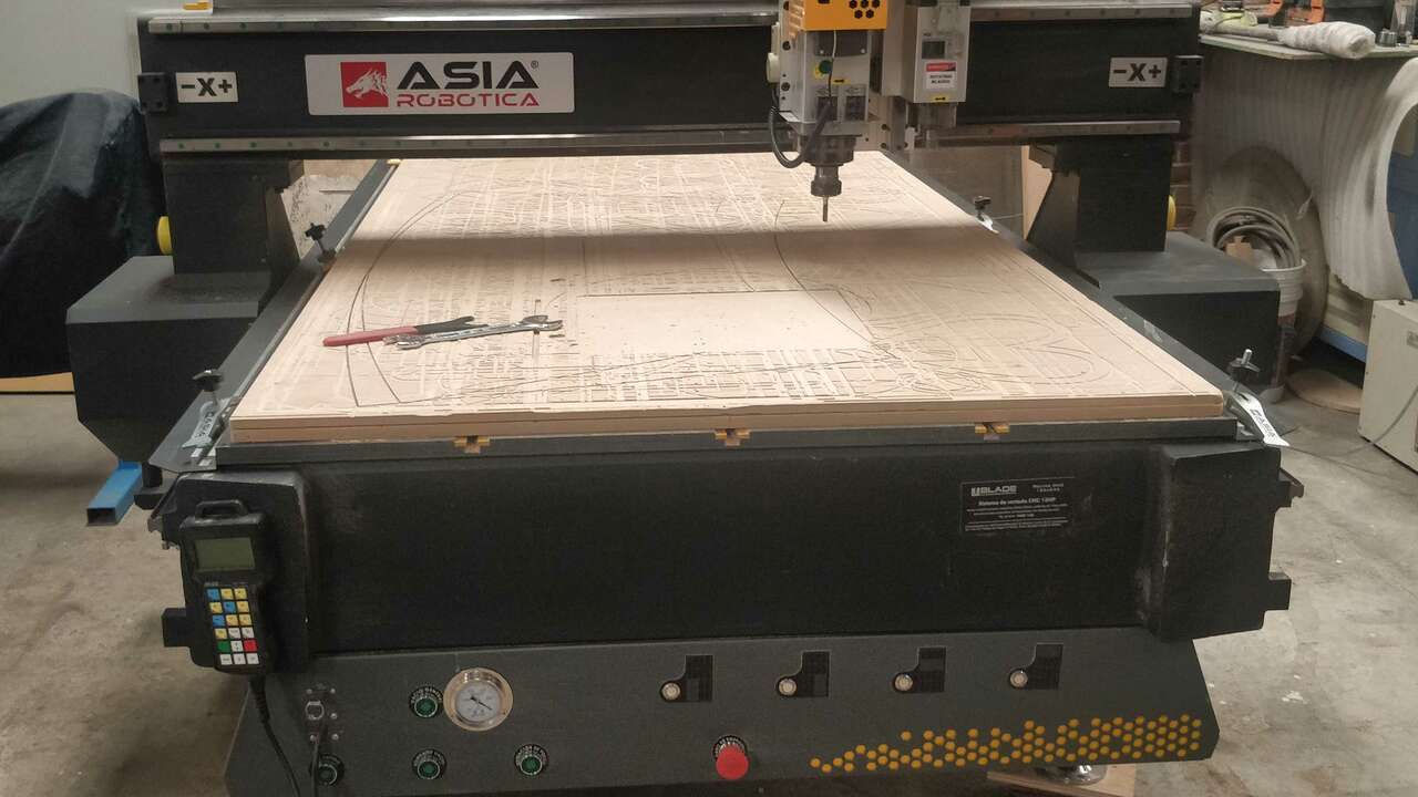
The router machine where I developed my practices is the WORKS 1325 from Asia Robotica. It is a really powerful machine since it is equipped with two spindles, 9HP and 2HP both of them are developed by HSD which is a italian brand and it is well known by the quality of its motors. A router machine uses a spindle and an endmill to produce a cut through materials. The router machines has a controller which reads G-code to route tool paths and created the required cut. There are multiple softwares where you can import a design or create one and calculate the required toolpaths to obtain the desired piece. Nowadays, there are many router sizes but the most commonly used are big and we can create whole cabinets, furniture, sculpture or almost anything we cn image. Nevertheless, the router manufacturers have been developing multiple deskotp CNC router which can be used the same day they arrive and they can cut small parts since the cutting dimension are small. The next figure displays the big machine that I used:
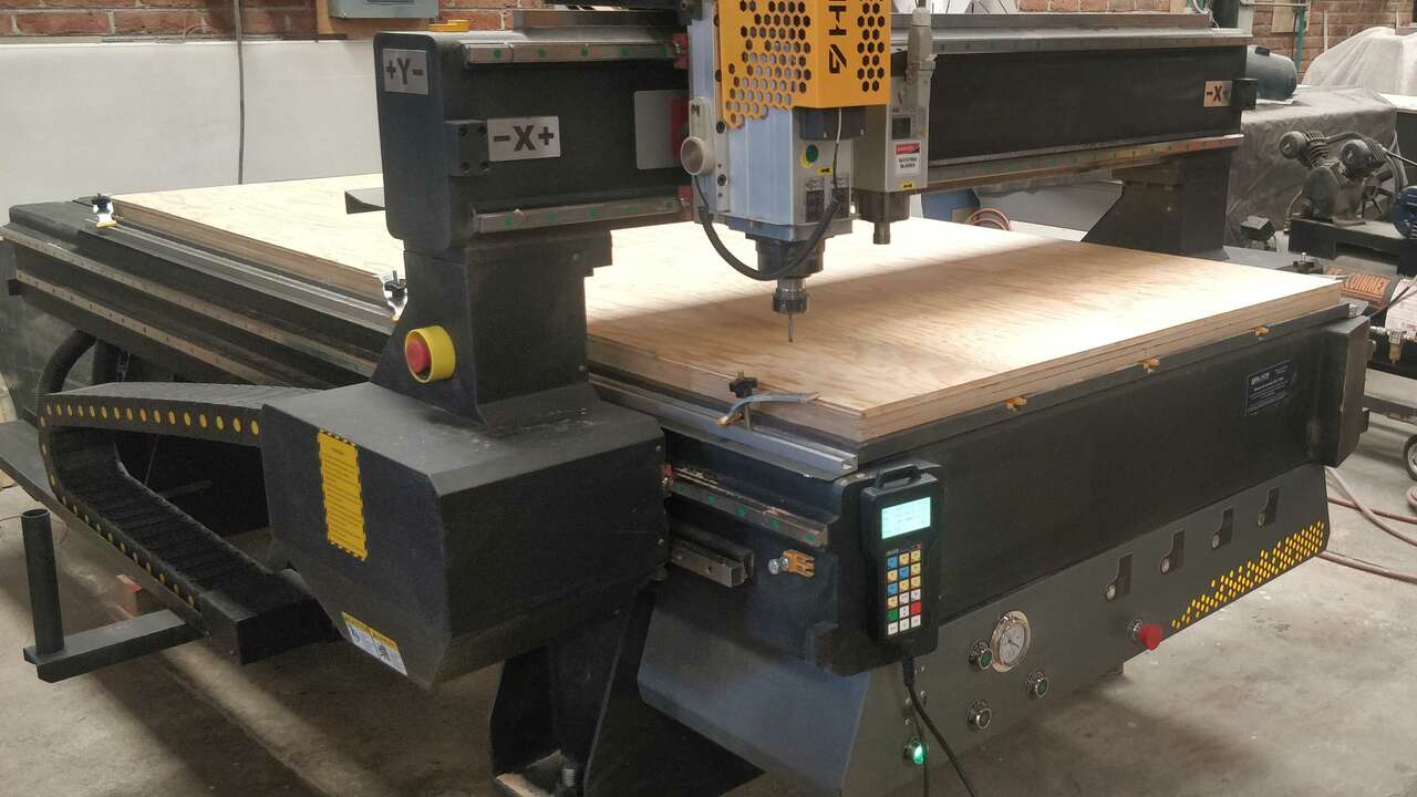
The following table shows the main specifications of the machine:
| Characteristic | Value |
|---|---|
| Model | Works-B |
| Working area | 1220 x 2440 mm |
| Spindle power | 9 HP/ 2 HP |
| Maximum feedrate | 30000 mm/min |
| Software | V-Carve Pro |
The supplier provided us with the following list of materials that can be cut and/or engraved with this type of machine:
- ABS
- Acrilyc
- AlUCOBOND
- Aluminium
- Copper
- Hard wood
- MDF
- Nylon
- Plywood
- Polycarbonate
- PVC
- Soft wood
Testing Router Machine
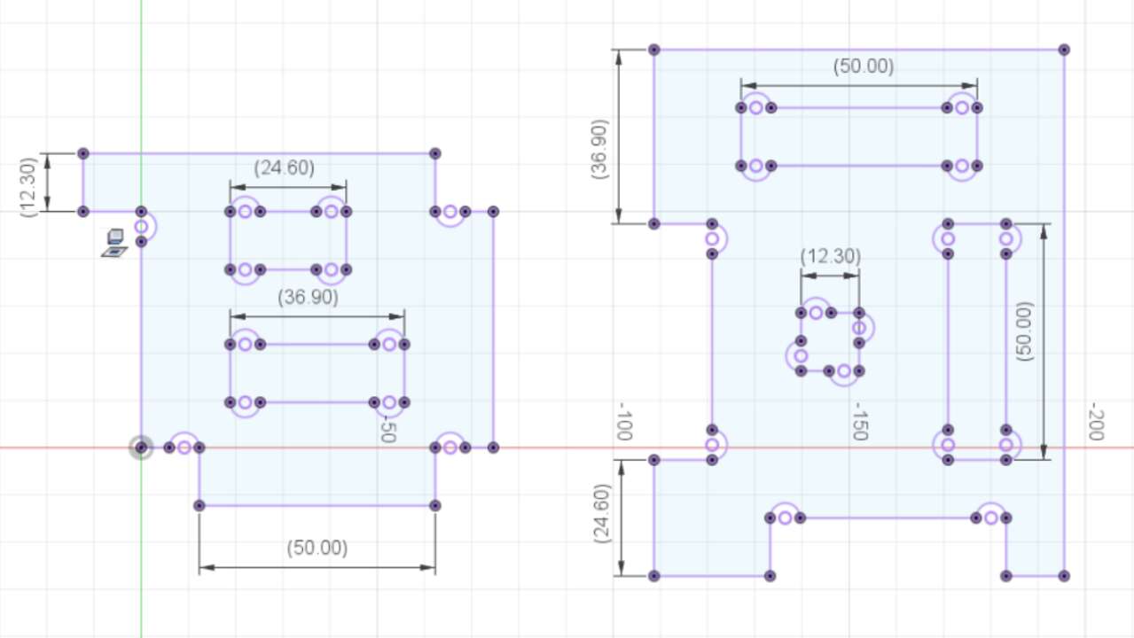
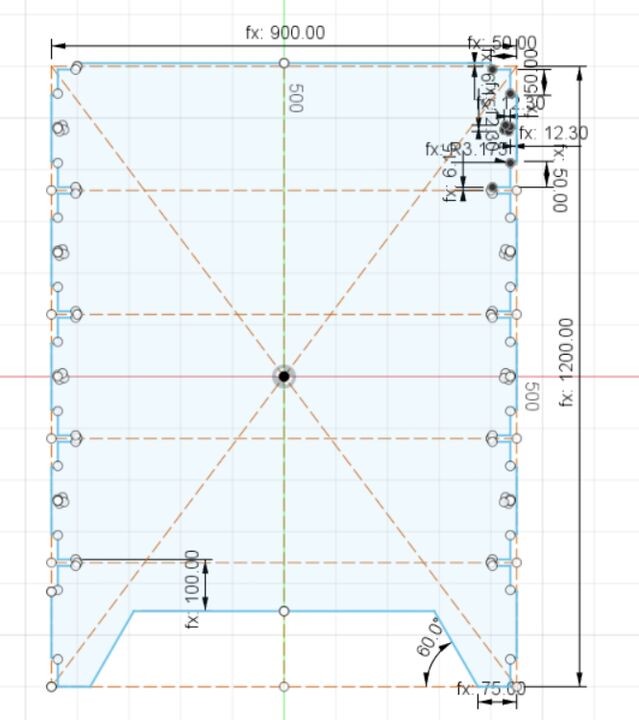
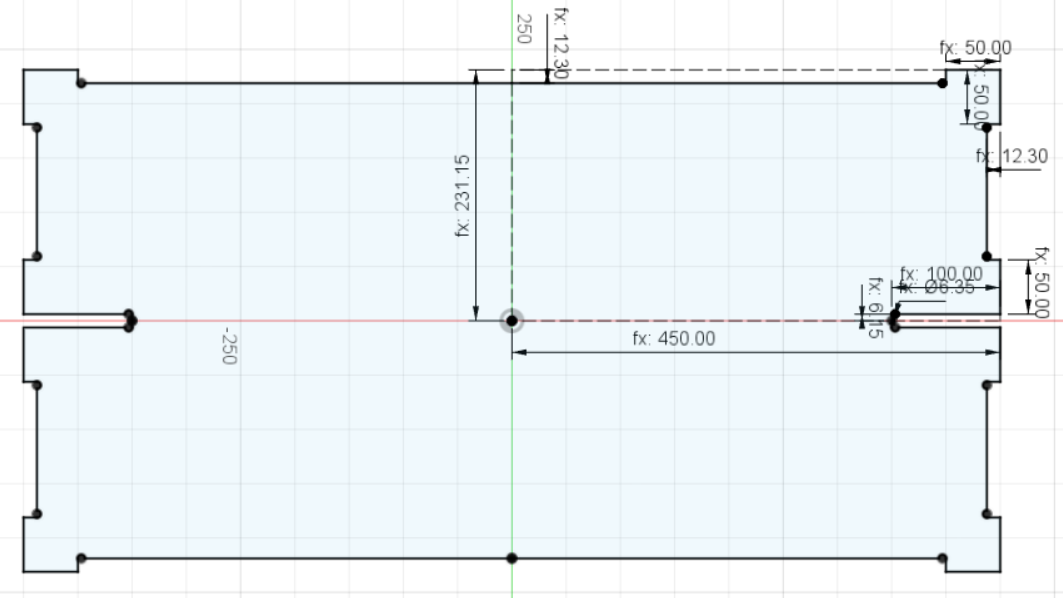
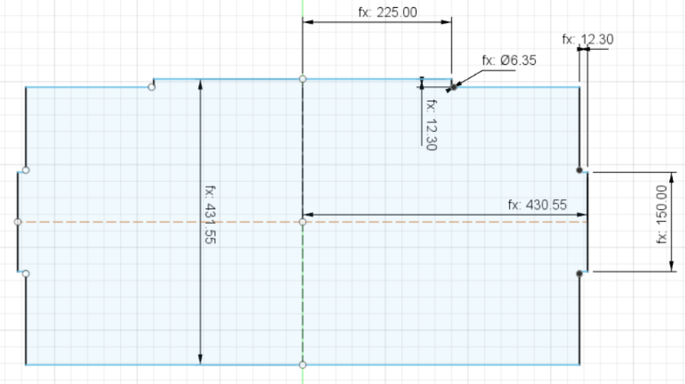
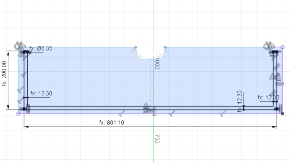
Since, I am the only one that is taking FabAcademy in FabLab Puebla that is in Mexico, I will document all the group assignment in my own webpage. Thus, I created a parametric file of a furniture where I can control the thickness of the material to do multiple tests on the material to be used and find the best dimension to make easier the assembling process. The following picture shows the design created in Fusion 360. It is important to note that the dimension that marks 12.3 mm is the dimension that can be modified depending on the parametric input.
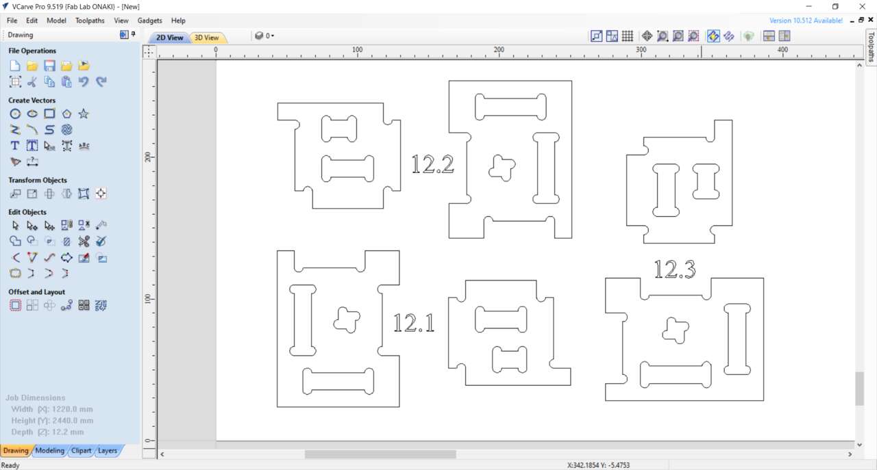
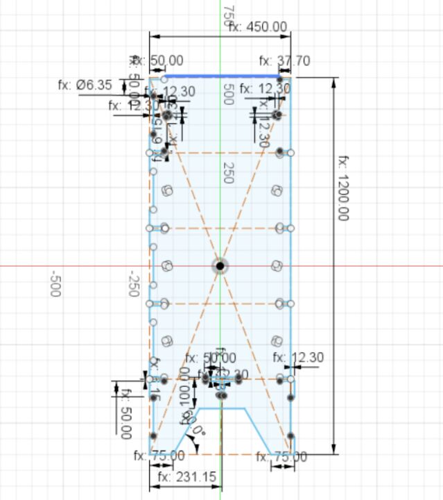
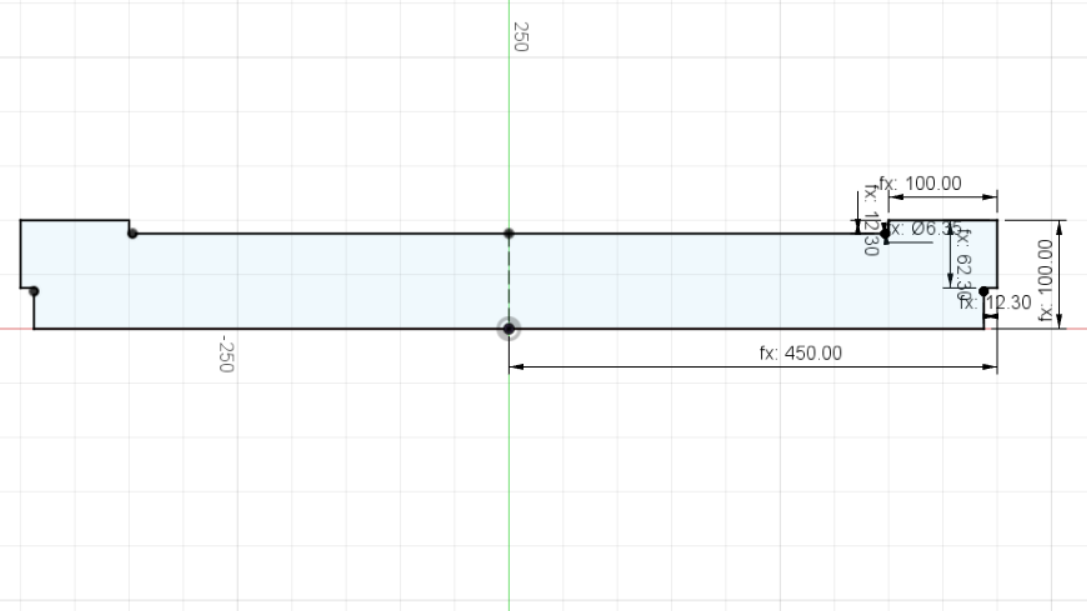
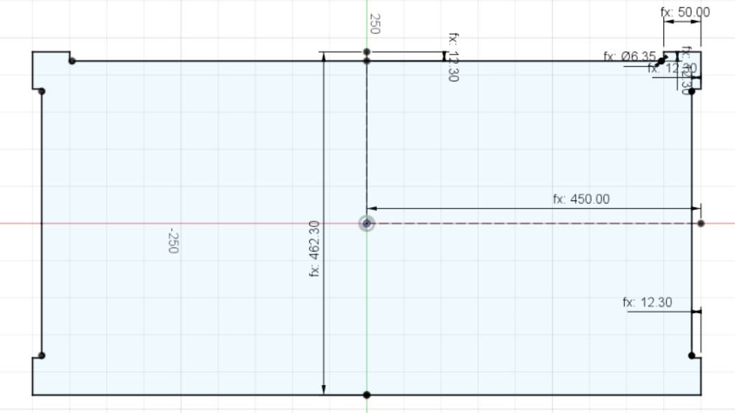
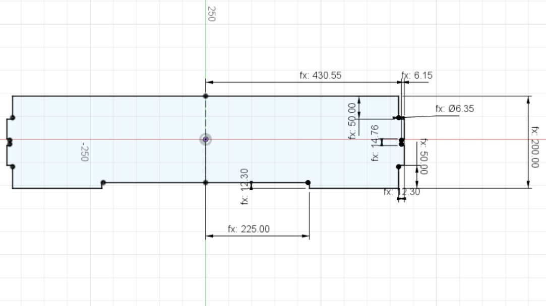
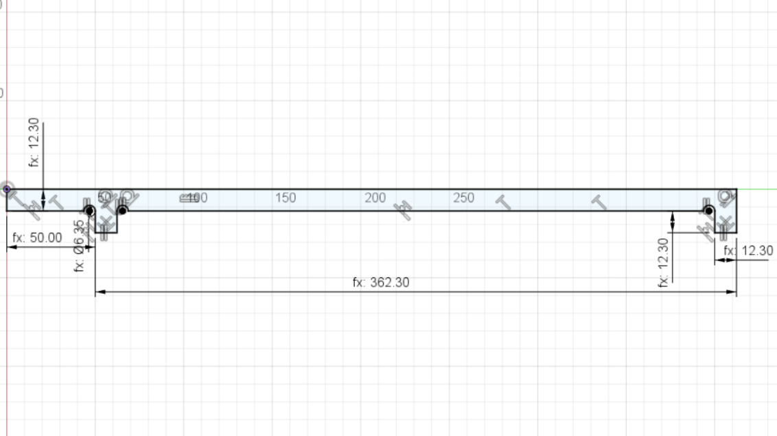
For this week I want to build something with a 12 mm thickness plywood. However, the real thicknes of the material when I measured was of 12.2. Thus, I changed the parametric thickness and test three different muasurements 12.1 mm, 12.2 mm and 12.3 mm. The file to be created is shown in the following picture.
Now it is time to create the profile toolpaths to cut the exterior and the slot in the pieces. To create the toolpath, you need to select the vector where the toolpath will be created and click on the toolpath menu that is on the right side of the window. But before se set the toolpath parameters, I calculated the spindle speed and the feedrate. There are two equations to calculate the cutting parameters which are the spindle speed and the feed rate, the following pictures shows the equation and the variables that we need to calculate them.
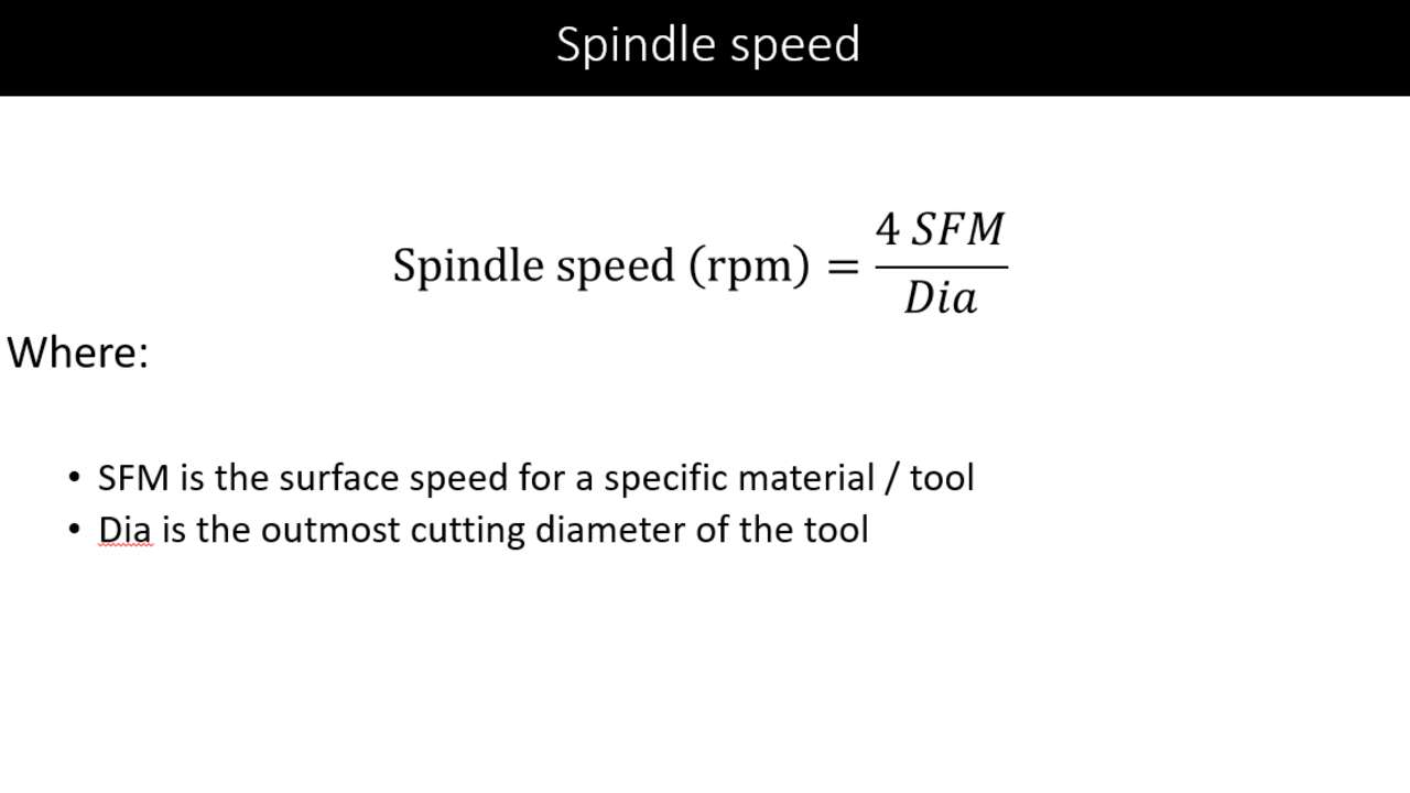
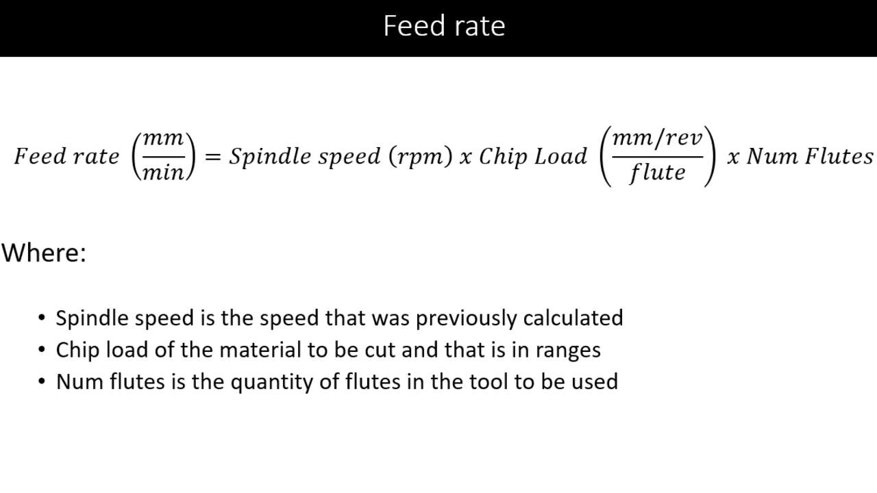
According to the previous equations we need to know the surface speed and the chip load of the material for soft plywood. And we also need to know the diameter tool and how many flutes it has. These parameters are shown below:
| Parameter | Value |
|---|---|
| Surface Speed | 16,510 mm/min |
| Chip Load | 0.28 - 0.33 mm |
| Diameter tool | 6 mm |
| Flutes | 1 |
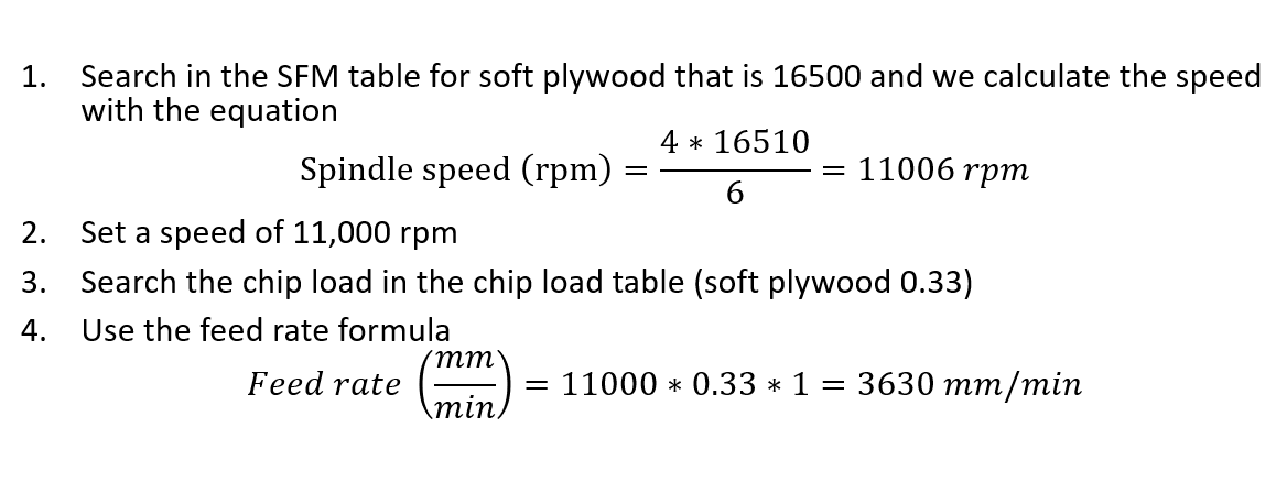
With these parameters, we can calculate the spindle speed and the feed rate with the following procedure:
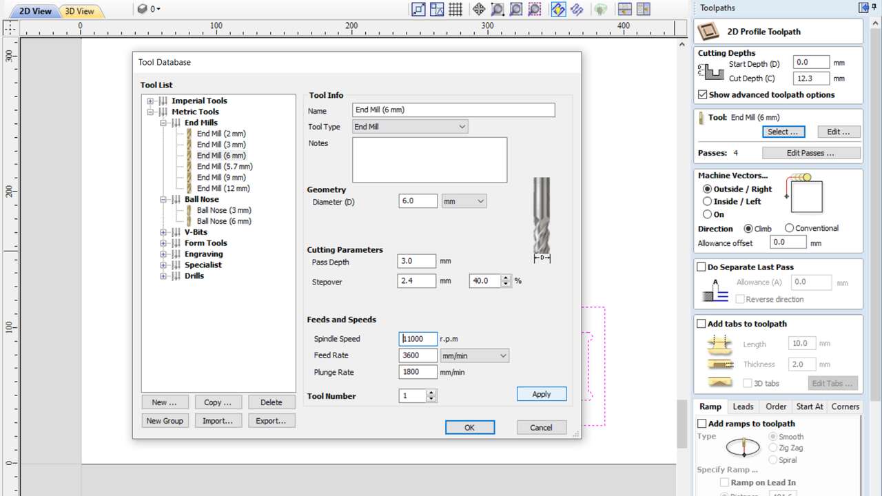
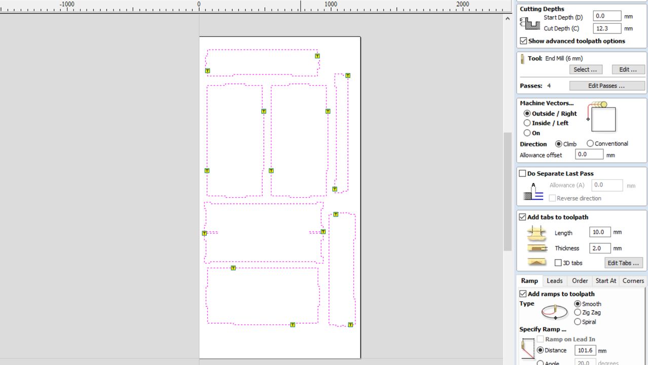
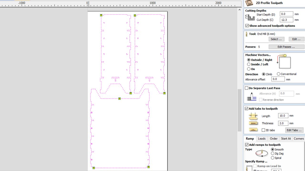
Now is time to move to VCarve and create the first profile toolpath. When selectin the toolpath, I set the "Cut Depth" to 12.3 mm to make sure that the endmill will go through the material. In the tool section, I clicked in "select" to choose the 6mm endmill that we have at the FabLab. When I selected that tool, I changed the parameters with the calculated parameters as shown in the following picture.
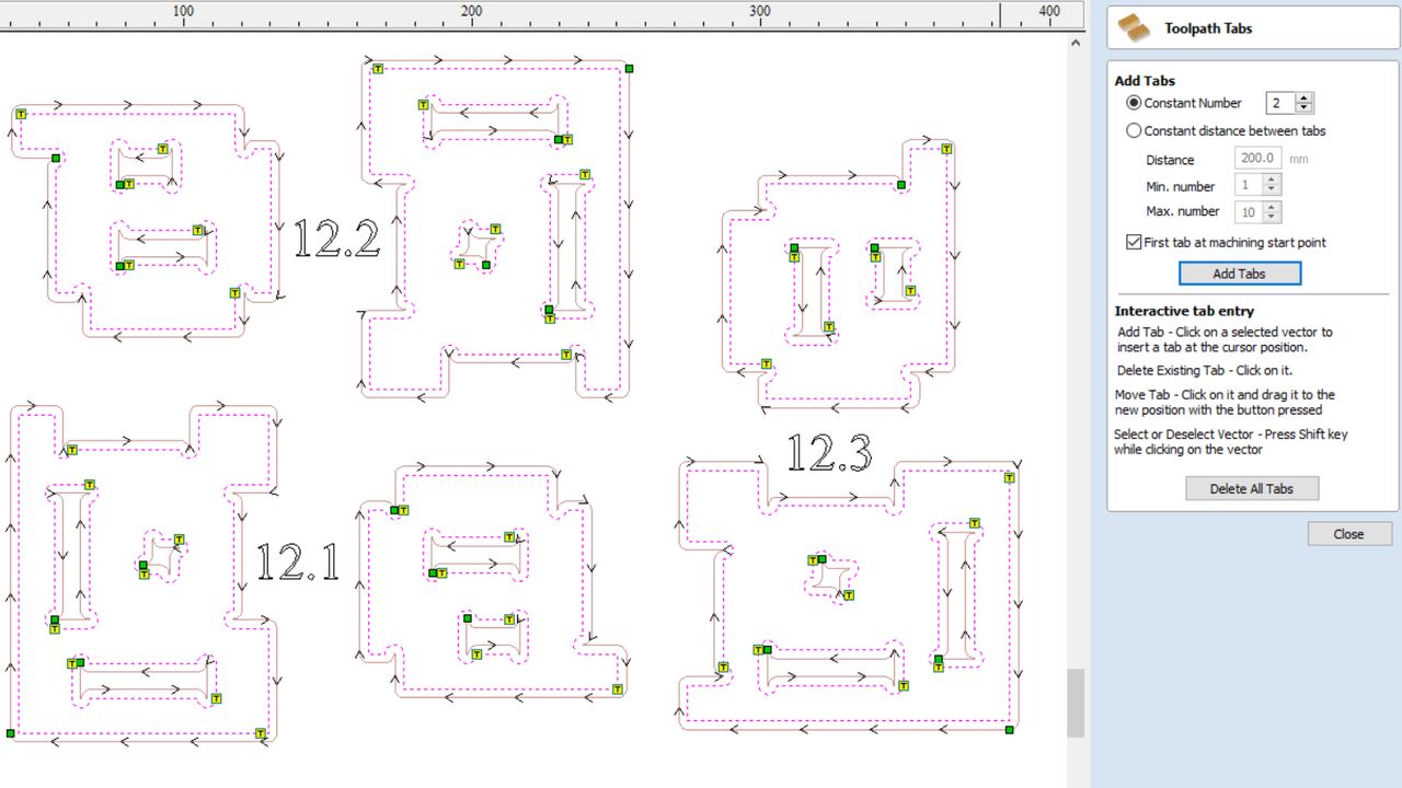
I set tabs of 2 mm thickness and with a length of 10 mm to avoid that the pieces move in tha last pass by the spindle speed. I added ramps in the entry point where I chose a smooth entry with a distance of 100 mm. After I set all those parameters I clicked on calculate at the end of the setting and the software showed me the next picture.
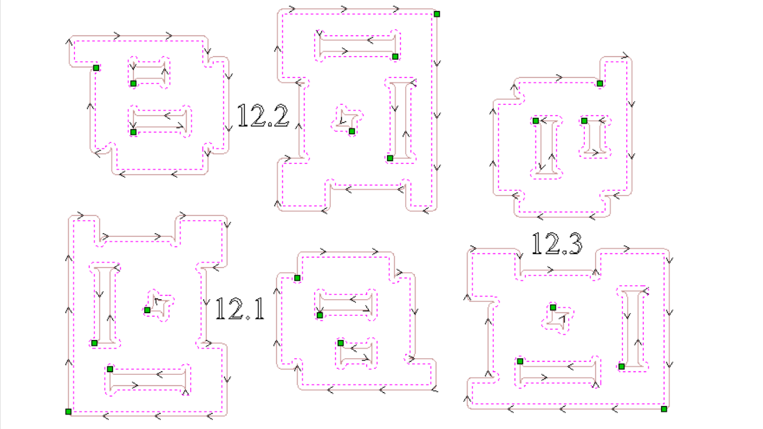
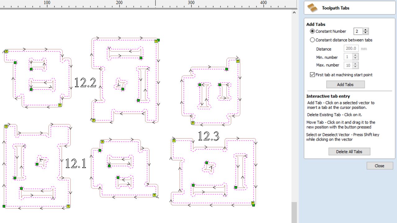
The lines with arrows show the paths that the tool will follow and the direction while the green points are the entry points of the tool. The most surprising thing is that the tabs were not display because I did not set them. Even if you click on add tabs you also need to click the button "edit tabs" to set the quantity, distance, or position of the tabs as the first window shows. Nevertheless, I did not want tabs in the interior of the piece. Thus, I deleted all the tabs and I left click where I want tabs as shown in the second picture.
The last part in the software is to select the right Post-Processor and save the toolpath as a G-code. This file was saved in a USB and plug it into the router control. Before plugging the usb with the file, I change the endmill with the machine off and with the tools that are shown in the first picture.
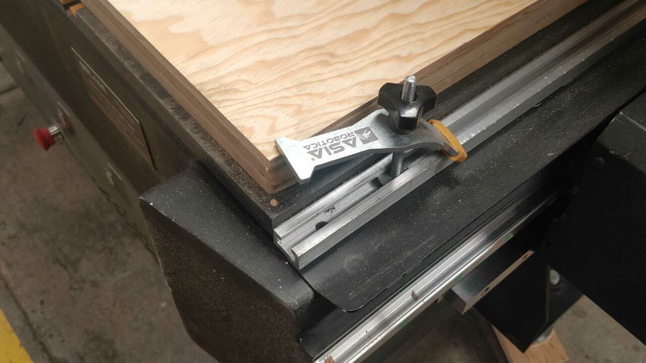
Afterwards, I place the plywood in the working table and I hold it the router clamps that were given by the manufacturer and which are really useful.
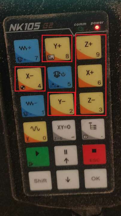
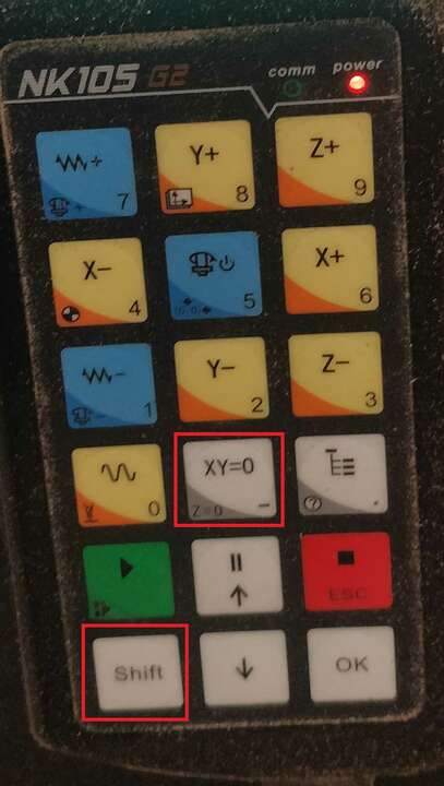
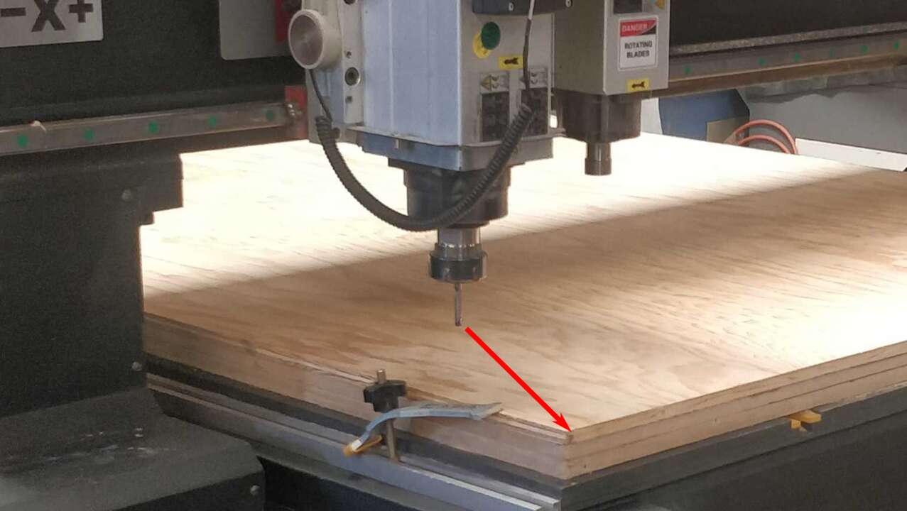
Now, it is time to reset the zero position in the router controller with the endmill and the material. To do that, I manually moved the tip of the endmil to the bottom-left corner and place it just over the material. The movement was done with the (X-,X+,Y-,Y+,Z- and Z+) of the DSP that are shown in the first picture. When the tool was perfectly positioned, I clicked the button XY -> 0 to set the XY position and later I click Shift + the same button to set the Z position.
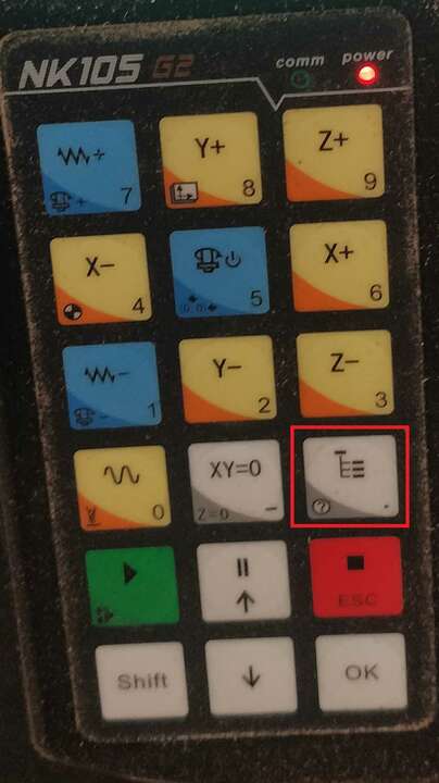
Finally, I sent the G-code and let the machine works. In order to do that, I connected the usb to the DSP, later I click the menu button that is shown on the first picture and later I move to select USB files with the arrows that are shown in the second picture
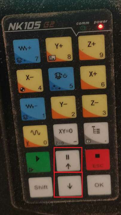
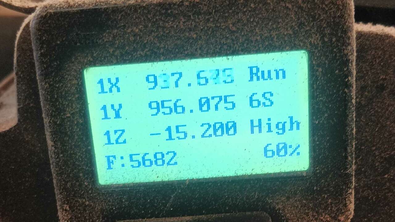
When I found the file to be sent, I click the green button that says OK and later I click the blue button with the number 1 to confirm the machinning process. Afterwards, You must see on the screen the actual coordinates of the endmill, with the feedrate and the spindle speed just like the picture above shows.
When the cut was done, I used a special tool to cut wood and with that tool I removed the tabs that were made by the router. However, at the end I had to use files and sandpaper to remove the tabs and smooth the edges.
After I tested all the slots, I realized that the parts with thickness of 12.1 and 12.2 mm were ok for some slots but not for all of them. Nevertheless, the thickness of 12.3 mm was the best because with that dimension all the slots fitted perfectly without problems. Therefore, I will use this thickness for my final design.
Make something big
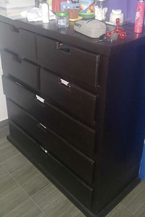
For this section I did not know what to do but during classe a link to get ideas to make furniture in the CNC was shared. This website is called At Fab and I helped me to decided what to do. After navigate the website, I remembered that my mom wanted a new drawer for her room at the beginning of the year and also that her birthday is very closed. So, I used the given sample of the website and a drawer that my mom likes to built my own drawer. The picture on the left shows the drawer presented in the website and the drawer on the right shows the drawer that my mom likes.

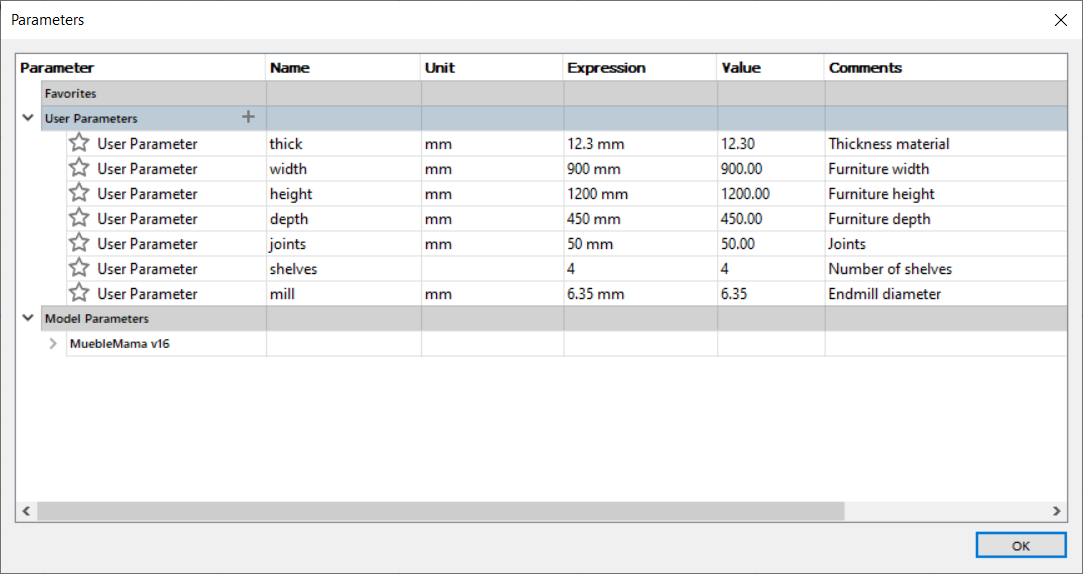
Now that I have the idea of what I will design, I decided to declared multiple parameters to make a parametric design and change the design according to the material thicknes. The next picture shows the parameter that I created along with its value and the use of it.
With the parameters, I can start creating the back part of the drawer and the sides. These parts must be assembled togheter and they must use the same parametric values.
After the back and the sides, I created the base of the drawer and its support.
The last two parts for the drawer frame are the top piece and the support front which are shown below.
Now it is time to create the sketches to build the drawers, first I sketched the base and the back pieces of the drawer.
Second, I created the drawer side which are the same but on is the mirror of the other. It is also important to note that the sides and the front pieces of the drawer contain a slot to move through the drawer and to fit the sides and the base into the front piece.
Finally, I created the front of the drawer and the support of the drawer. This support is meant to be the part where the whole drawer will slide in ordet to move.
The following picture depicts the final assembling of my drawer
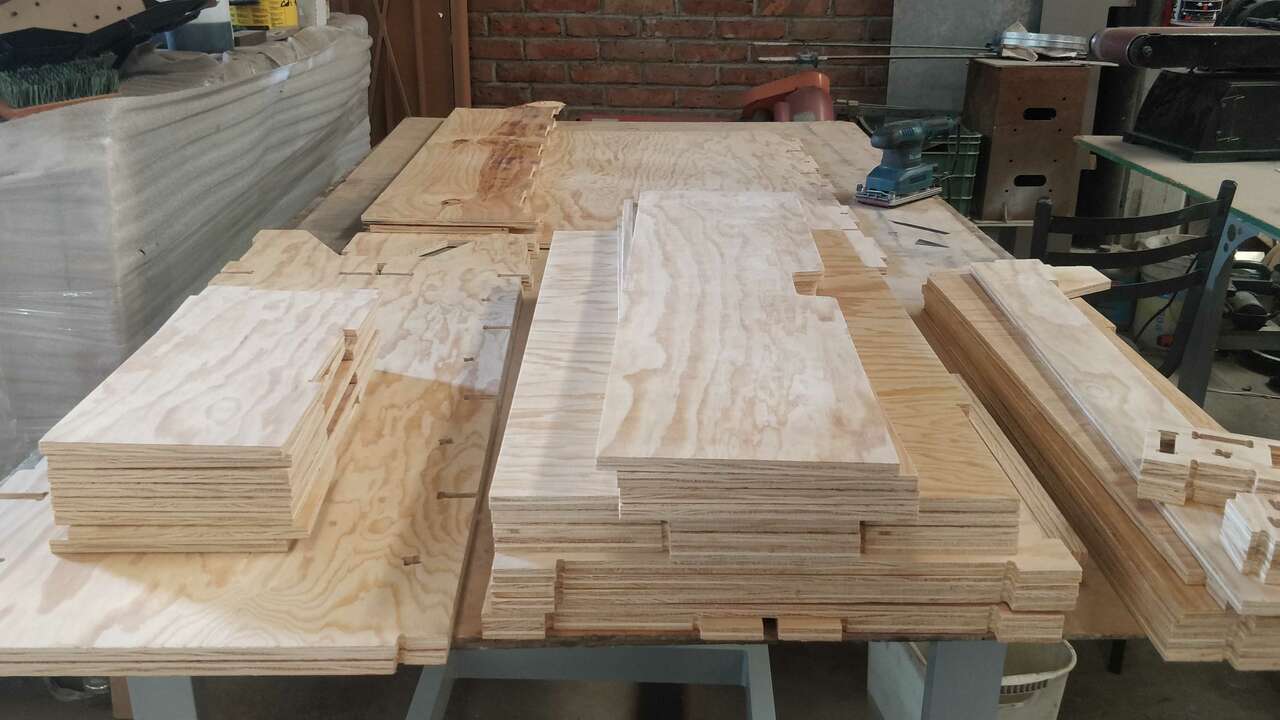
When I finished all the parts and I verified that my assembling worked perfectly in the Fusion 360. I proceed to save a single dxf file for each part because in Fusion 360 they are declared as individual components. After all the dxf were design I import each of them into VCarve Pro and start moving aroung to spend as less as possible of the plywood. Thus, the following picture shows how I organized each triplay to be cut.

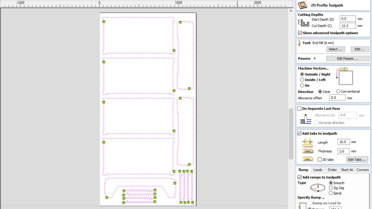
Later, I create the profile paths for each plywood where I used the same cutting parameter as the testing parts created at the beginning. It is important to note that each part has two tabs to avoid any movement on the pieces. The two following pictures illustrates the profile paths created for the first two plywoods.
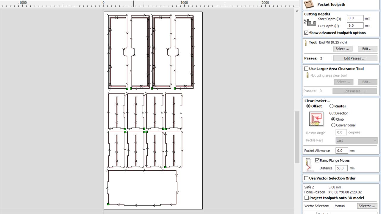
The next two parts show the other two plywoods. However, the last plywood has something different beacuse I had to create a pocket toolpath to create a slot in the drawer parts. When the pocket toolpath was done, I created a profile toolpath to cute the pieces in the same way as the previous parts.
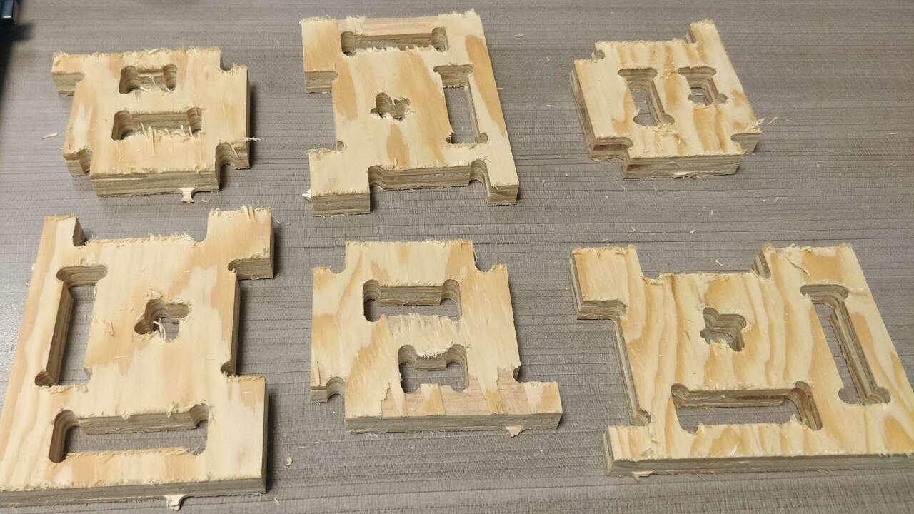
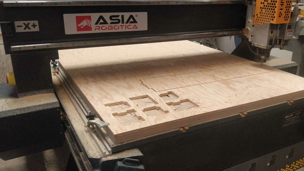
Once I generated all the required gcodes that contain the router toolpaths. I proceed to place plywood by plywood and send the file to cut with the same procedure that was shown in the previous section with the testing pieces. The followings pictures shows the machining process of some of the parts.
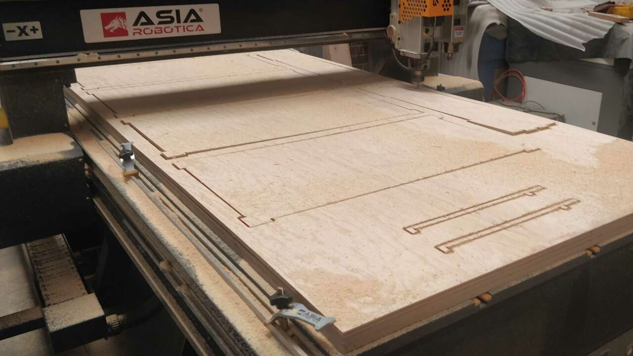
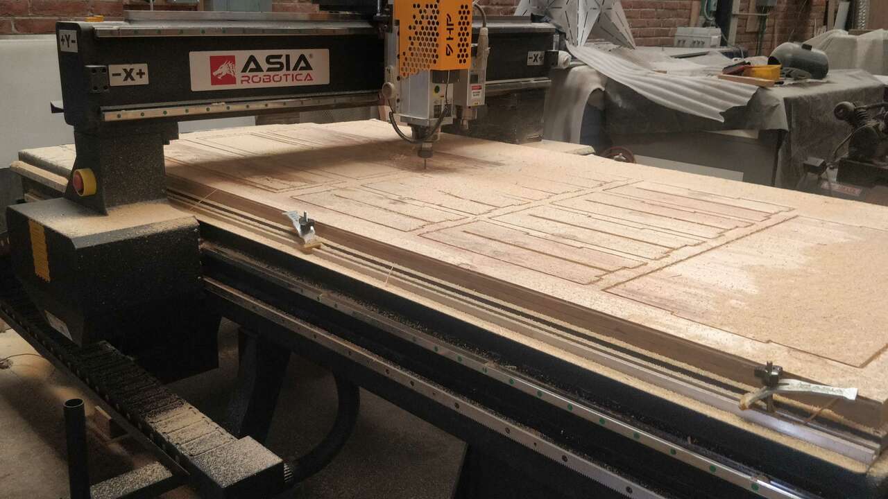
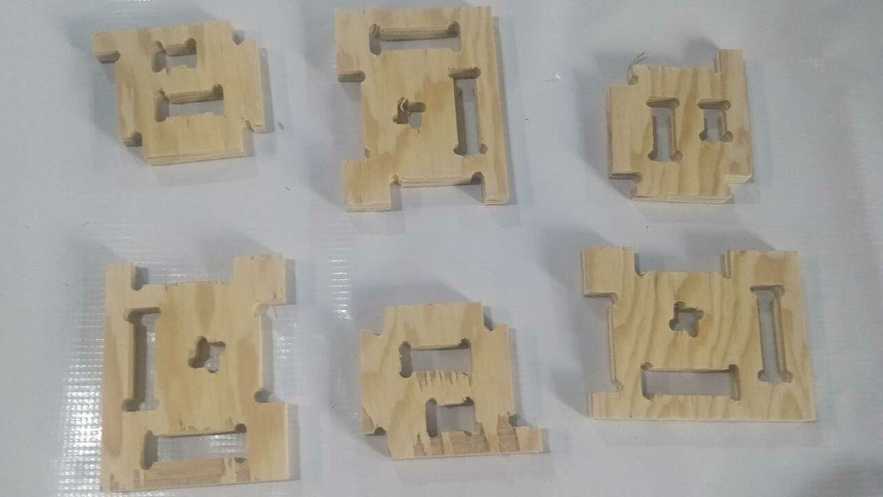
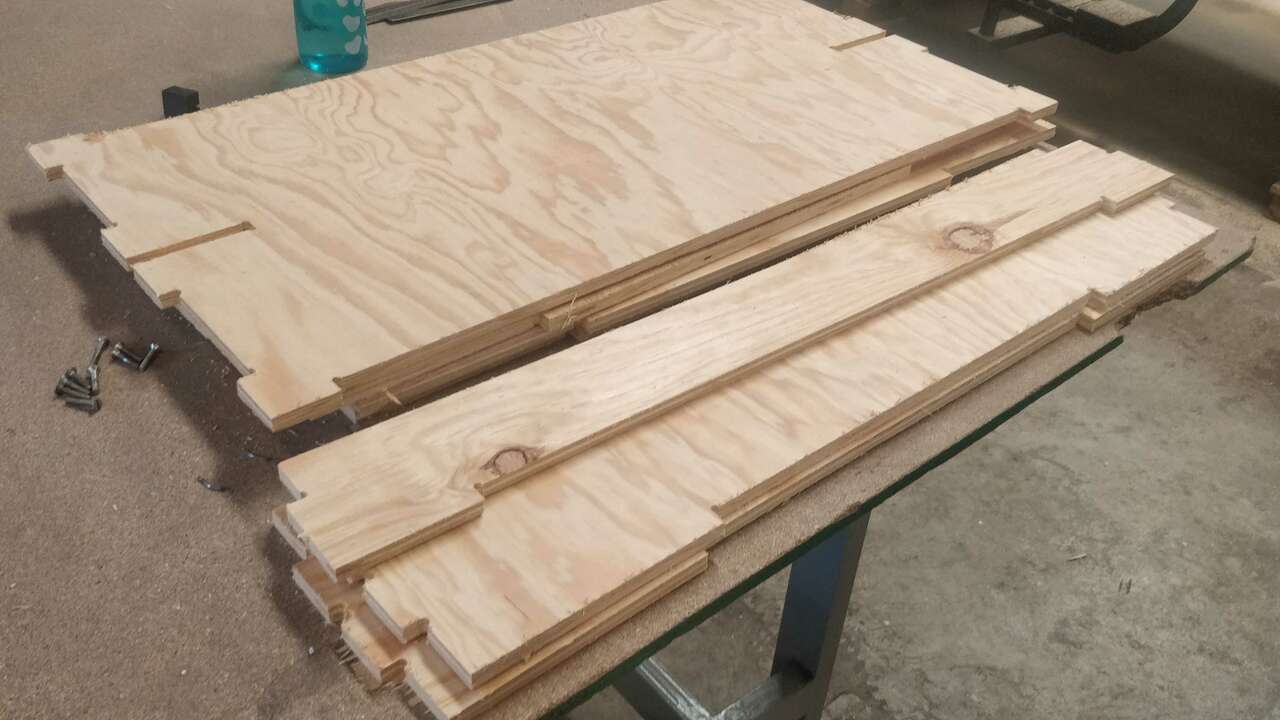
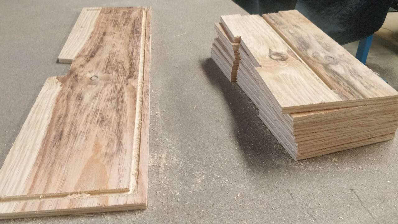
When I finished the machining process in the router, I used sandpaper to smooth the edges of all the pieces. The pictures above show how the parts came out of the machine and the last picture show all the parts.
Here I show an small video when the router machine was cutting.
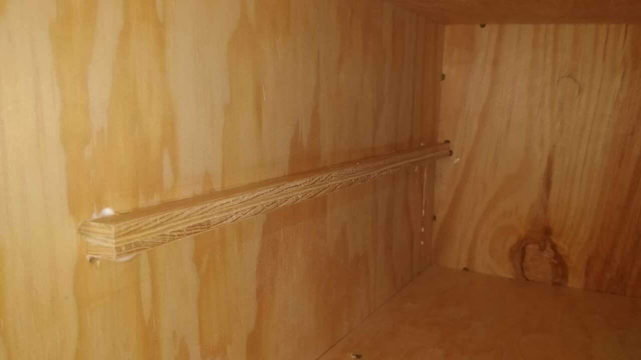
After I cut and sanded all the pieces, I started assembling the main frame with the use of wood screws of #6 x 1 1/2" and glue for some parts as the drawer supports. The next pictures show how the frame was assembled and the drawer supports.
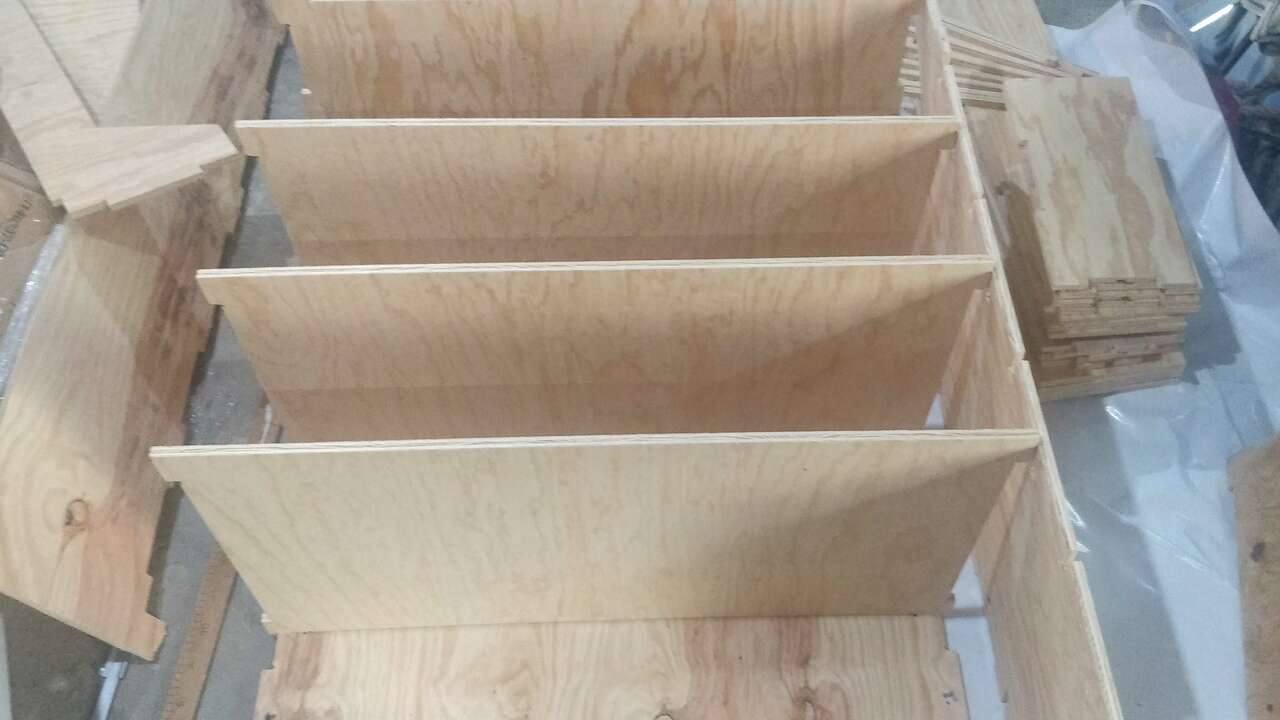
The asembling process of the drawer was a way easier than the main frame because they are small and it is easier to manipulate. Nevertheless, it was also a challengue because the front piece of the drawer has a slot where the rest of the pieces enter with pressure.
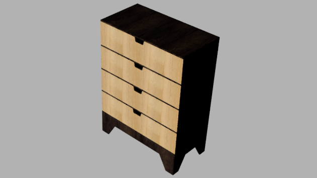
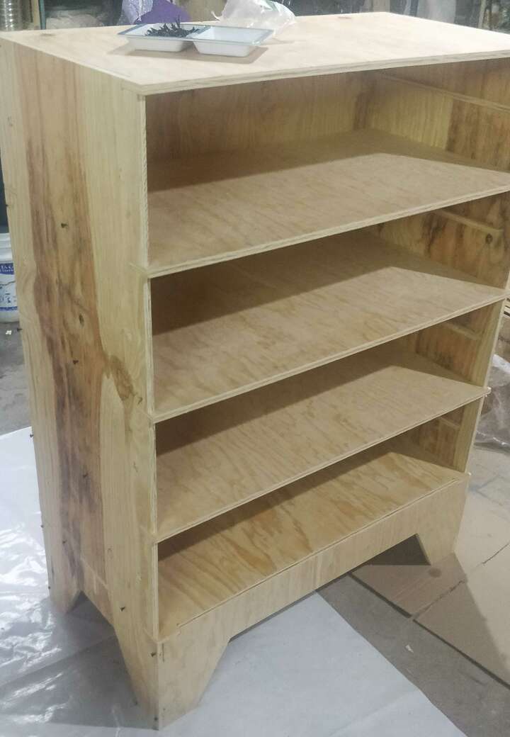
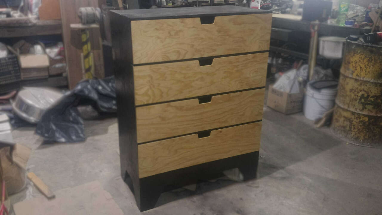
Finally, I used dark oak and transparent varnish in all the pieces. The dark oak was used in the main frame while the transparent in the drawers. I really love the assembling process and the final result is shown below.
I got the chance to give the drawer to my mom and I think she look very happy with it.
Files created
Useful Resources