3D Scanning and Printing
3D printing
3D printing or additive manufacturing (AM) is a manufacturing process of making three dimensional object from a digital (3D shape). The creation of the 3D object is achieved through an additive process which means that the object is manufactured by laying down successive layers of material until the objected is created. This technology was initially developed in the 80's for industrial use. However, during the past decade 3D printers have been developed for desktop/personal use.
3D printers utilize an onboard controller to manipulate the printer head and build a plate to print each 2D layer in the right order and position. Nowadays, these printers are compatible with sotwares that slice the 3D design, adjust the settings of the printer, and generate a set of instruction in machine laguage called G-code. The 3D design can be drawn by a CAD software which was previously analyzed during the course and they can also be created through 3D scanning process which I will talk at the end of this assignment.
There are many 3d printing technologies and some of them are:
- Stereolithography (SLA)
- Selective Laser Sintering (SLS)
- Fused Deposition Modeling (FDM)
- Digital Light Process (DLP)
- Multi Jet Fusion (MJF)
- Direct Metal Laser Sintering (DMLS)
- Electron Beam Melting
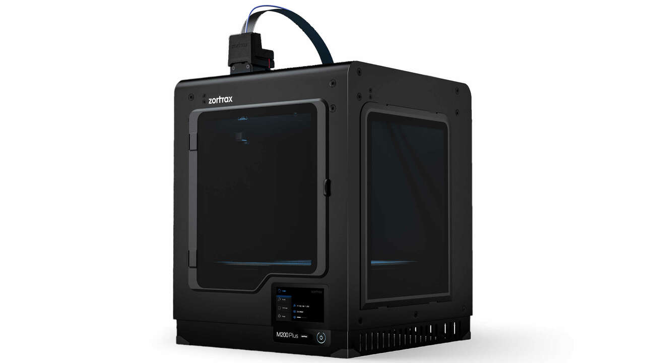
Its main specifications are:
- Build volume: 200 x 200 x 180 mm
- Material diameter: 1.75 mm
- Materials:PLA, ABS, CPE, PC, Nylon, TPU 95A
- Nozzle diameter: 0.3, 0.4 and 0.6 mm
- Layer thickness: 90 - 390 microns for a 0.4 mm nozzle
- Maximum printing temperature: 290° C
- Software: Z-SUITE
- Others: Automatic measurement of platform points' height, Wi-Fi, Ethernet, USB and Camera included
At the FabLab we also have the Form 3 from FormLabs which uses stereolithography. This technology is the original 3D printing process, and it is commonly known as resin 3D printing. The 3D object in these machines is created by selectively curing a polymer resin layer by layer using an ultraviolet laser beam. Therefore, the materials used in SLA technology must be photosensitive thermoset polymers that come in a liquid form.
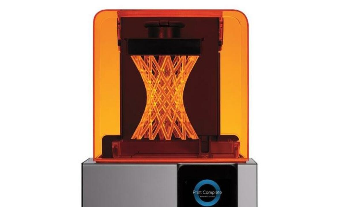
Its main specifications are:
- Build volume: 145 x 145 x 175 mm
- Materials: Photopolymer resin
- Layer thickness: 25 - 200 microns
- Software: Formlabs Preform
- Others: Wi-Fi, Ethernet, and USB
Testing 3D printers
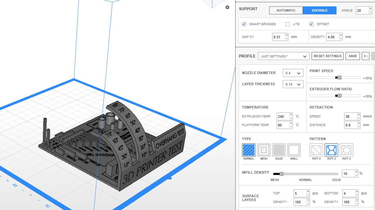
Since, I am the only one that is taking FabAcademy in FabLab Puebla that is in Mexico, I will document all the group assignment in my own webpage. To analyze the limitations of each printer, I decided to use a torture test developed by majda107 and can be found here. This design has overhangs, bridges, holes, supports, thin walls and more to find all the possible limitations that the machines could have. However, The form 2 printer was not working and I was only able to do the test in the Zortrax.
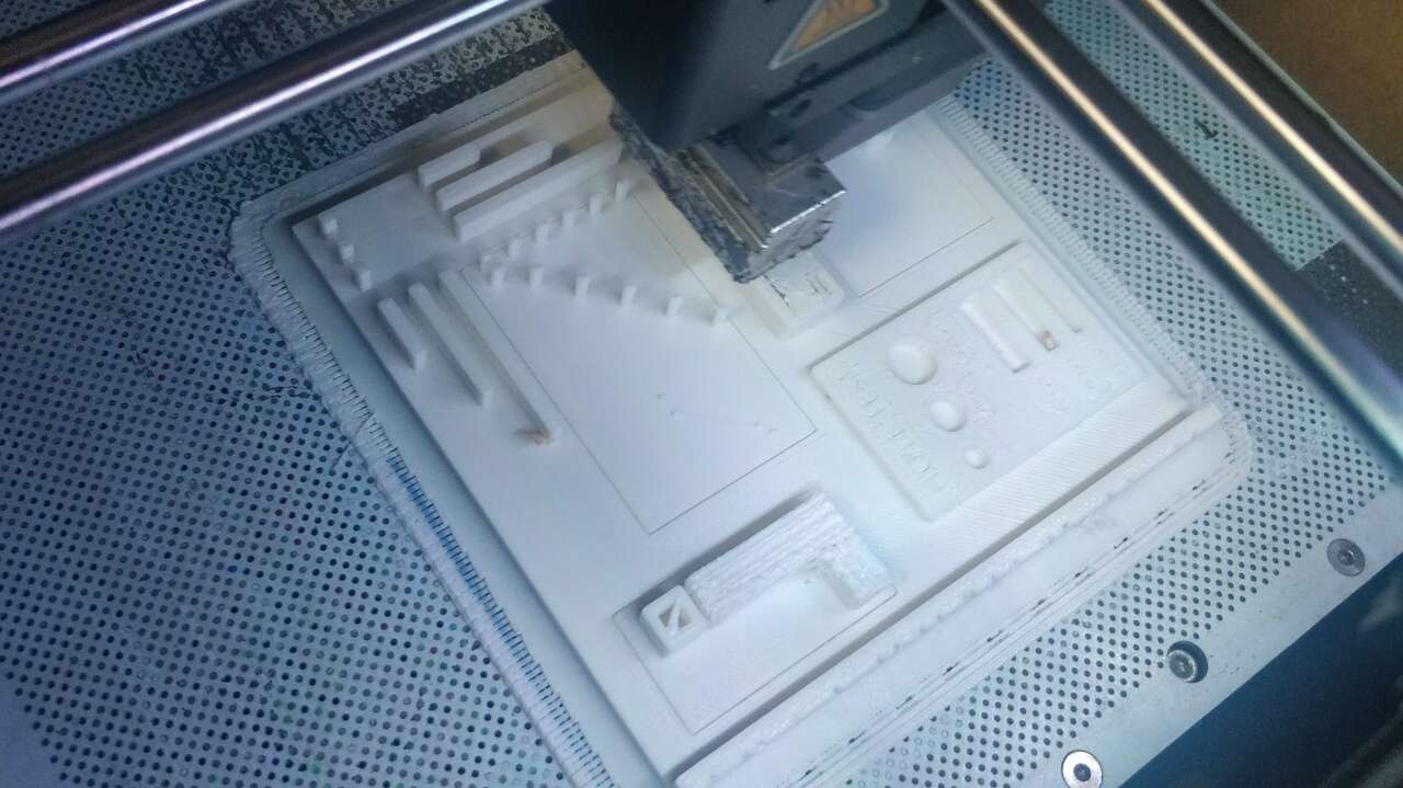
The test was printed in ABS with 0.15 mm layer thickness and 10% infill, the following pictures show the main setting as well as the printing process of the object.
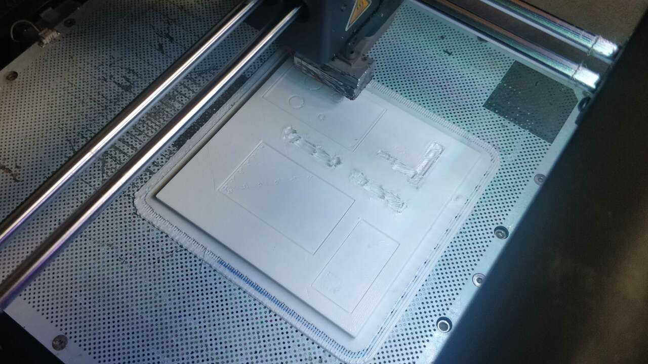

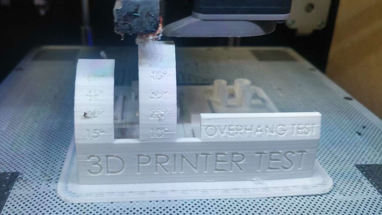
In the next picture is clear that the machine needs support after 60° becase the material got stuck in one place.
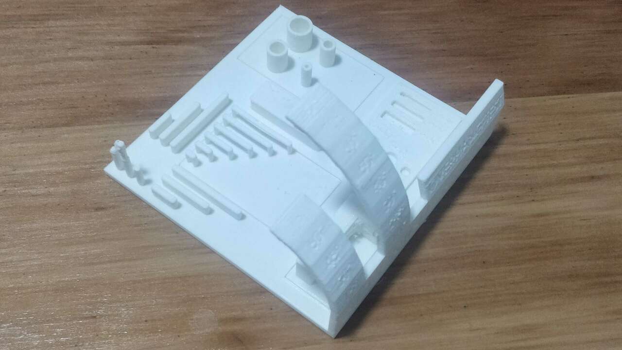
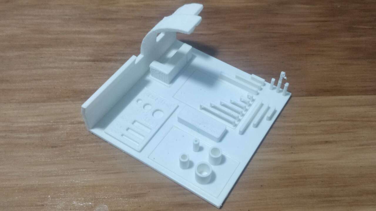
Above, the final piece can be appreciated from the back
The following table depicts the main results of the testing part
| Test | Expected Value | Real Value |
|---|---|---|
| Overhang | No support up to 80° | Needs support after 60° |
| Bridges | No support up to 25 mm | No support up to 25 mm |
| Holes | 2, 3, and 4 mm | 1.8, 2.8, and 3.8 mm |
| Cilinders | 4, 6, 8, and 10 mm | 4, 6, 8, and 9.9 mm |
| Small towers of 2 mm | 10, 20, and 30 mm height | After 10 mm it does not keep the shape |
Design to be made by 3D printers
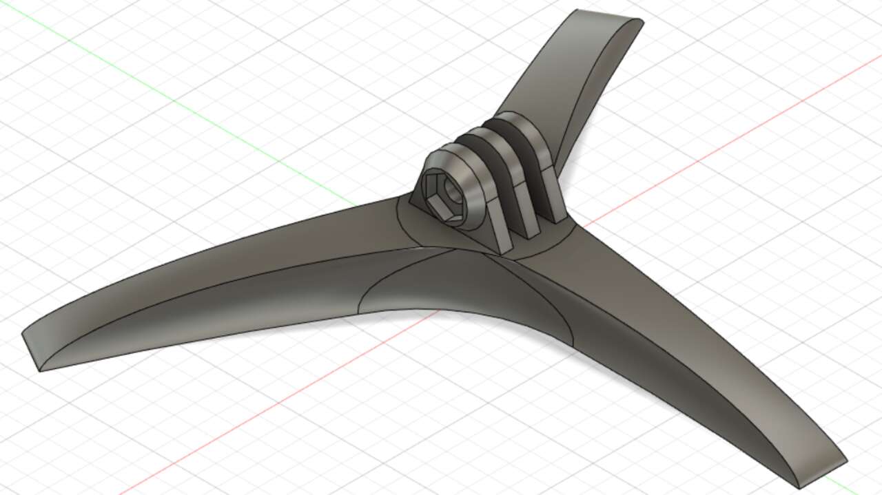
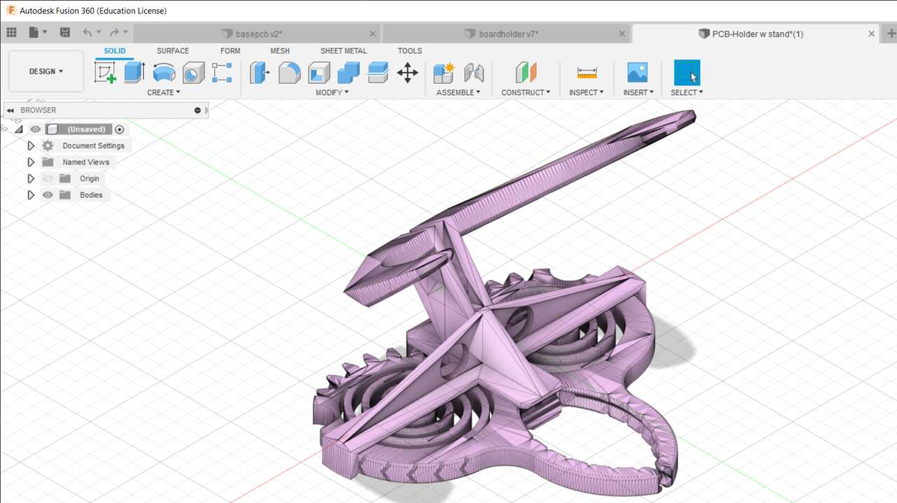
Regarding the assignment to print and design something that cannot be made subtractively. I did a research to find an inspiration about a design that I want to develop and I found out that there is one guy who created a PCB holder and can be found here. Nevertheless, I wanted to improved the design to be used in a separate base and also increased the semicircles to open the gripper.
The gripper I want to create can only be made with 3D printer since it is made in a single 3D printing. There will be a small gap between both gears and between the gears and the support which allows us to break the possible support that was generated by applying a small amount of force or by using a cutter. It is not possible to manufature the same design with a sustractive process unless the whole design is changed to multiples small files to create each component separately and it is possible that we need to add some bolts and/or bearings.
Base
Thus, I started with the base which was relatively easy. First, I draw an sketch with a triangular shape for the base and later I created another sketch with an offset of 15 mm that only containd a circles that was cut by the first plane.
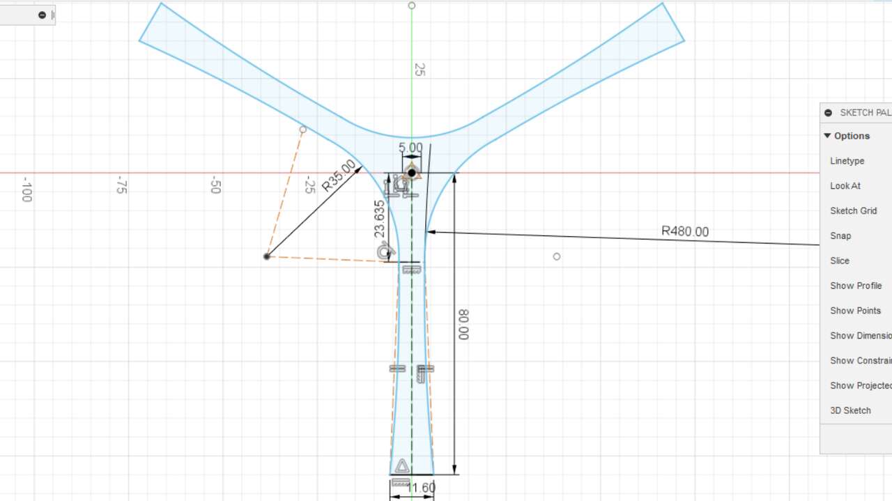
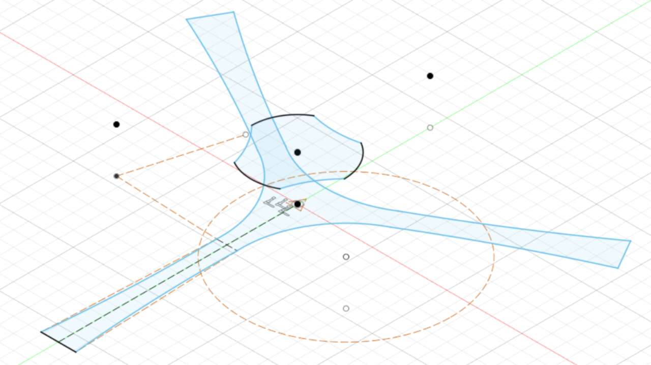
Once these two plane were created, I executed a Loft operation between both sketches. This operation is under Solid->Create->Loft and you just need to select both planes. The next part was to support for the gripper, so I draw three support with the same shape on the base center.
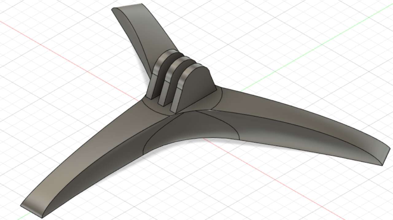
Finally, I create a cilinder with a chamfer and a hexagon hole to hold a nut in order to place a bolt and make pressure over the gripper.
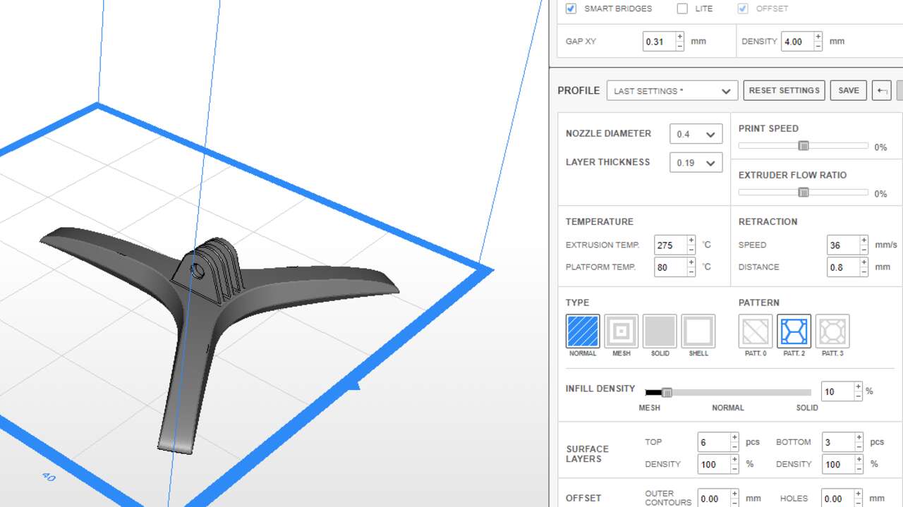
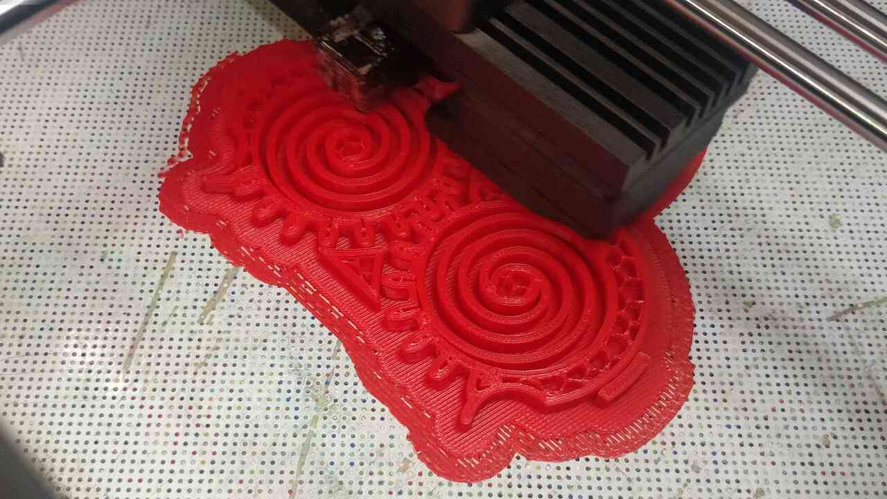
The design was transform into a stl file and later sent to the 3d printer. The base was printed in was printed in ABS with 0.20 mm layer thickness and 10% infill, these setting and the rest can be seen in the first picture, and the following pictures show the printing process.
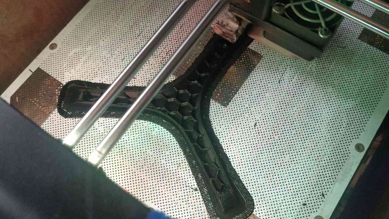
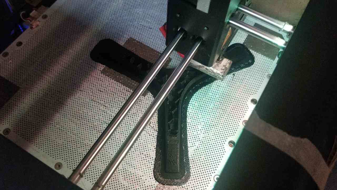
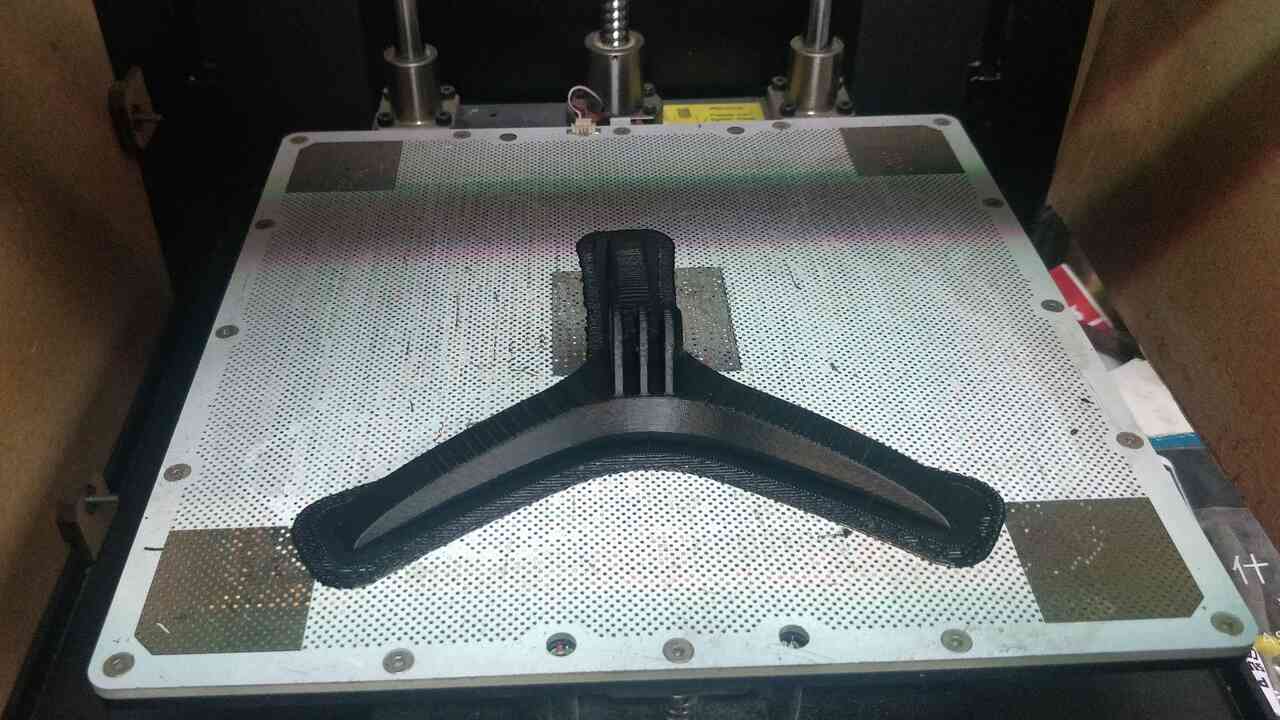
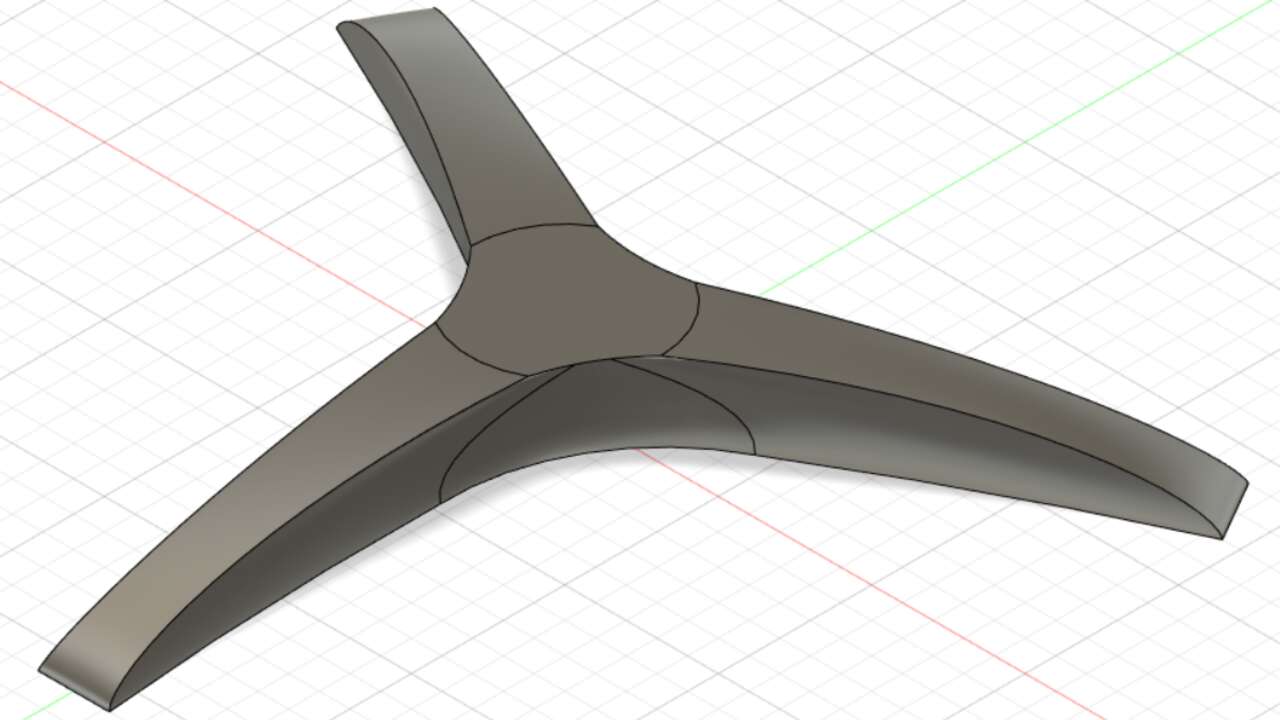
The result was pretty awesome and it is shown in the picture above:
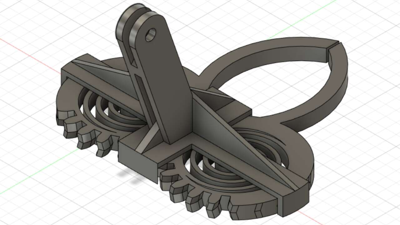
Gripper
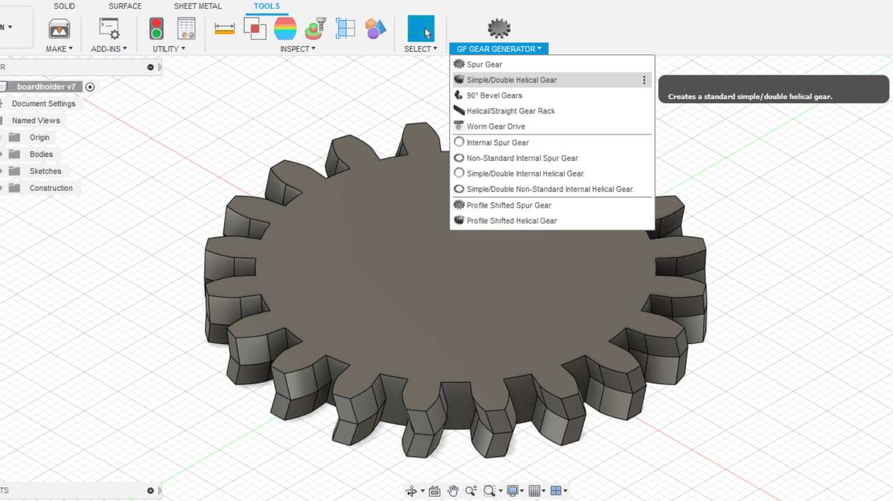
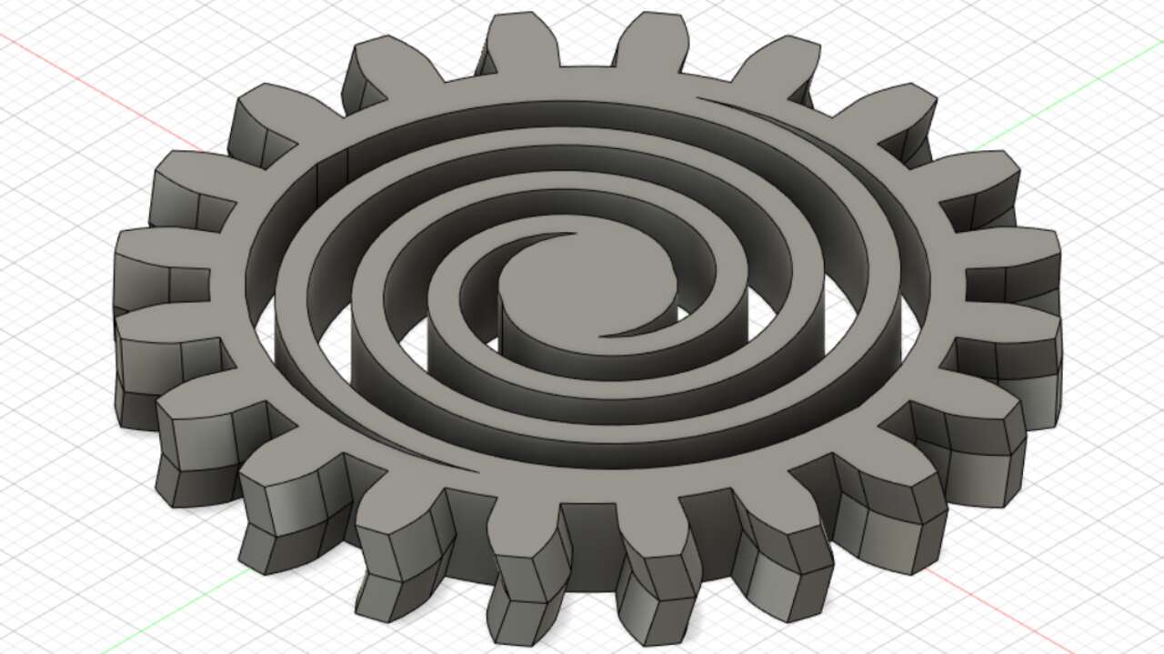
Since we cannot edit and STL file easily, I measured the gripper in the first picture and extracted the main dimensions to recreate the gripper. Thus, I started with a double helical gear which was created with an Add-In called GF Gear Generator and can be download here. To install it, you just need to double click on the file, restart Fusion 360, go to the tools menu under Add-Ins, on the new window select Add-Ins again and search for GF Gear Generator, finally click on play while selecting the Add-Ins. In my case, I used a gear of 20 teeth with a module of 2.5 mm and a height of 6 mm. These setting were set to avoid that set the diameter of the gear and avoid that a bridge between the center and a edge does not exceed the 25 mm that were tested in the first file.
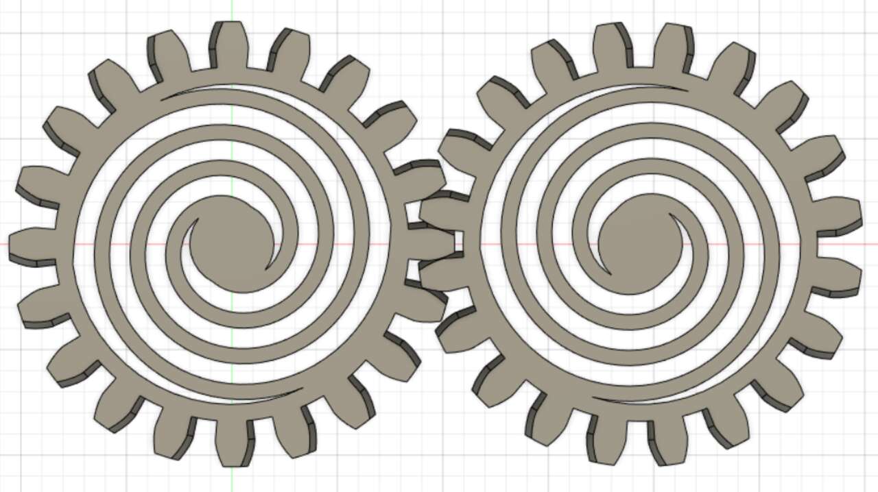
With the gear creation, I was able to extracted material in the middle of the gear and leave two spiral that have the function to close the gripper when external force is not applied. Later, I mirror the gear while leaving and offset of 0.5 mm between teeth.
Now is time to create the gripper as well as the required support to keep in place the gear when they move. These supports were used to created a plate over the gear with a clearance of 0.5 mm between the gear and the plate.
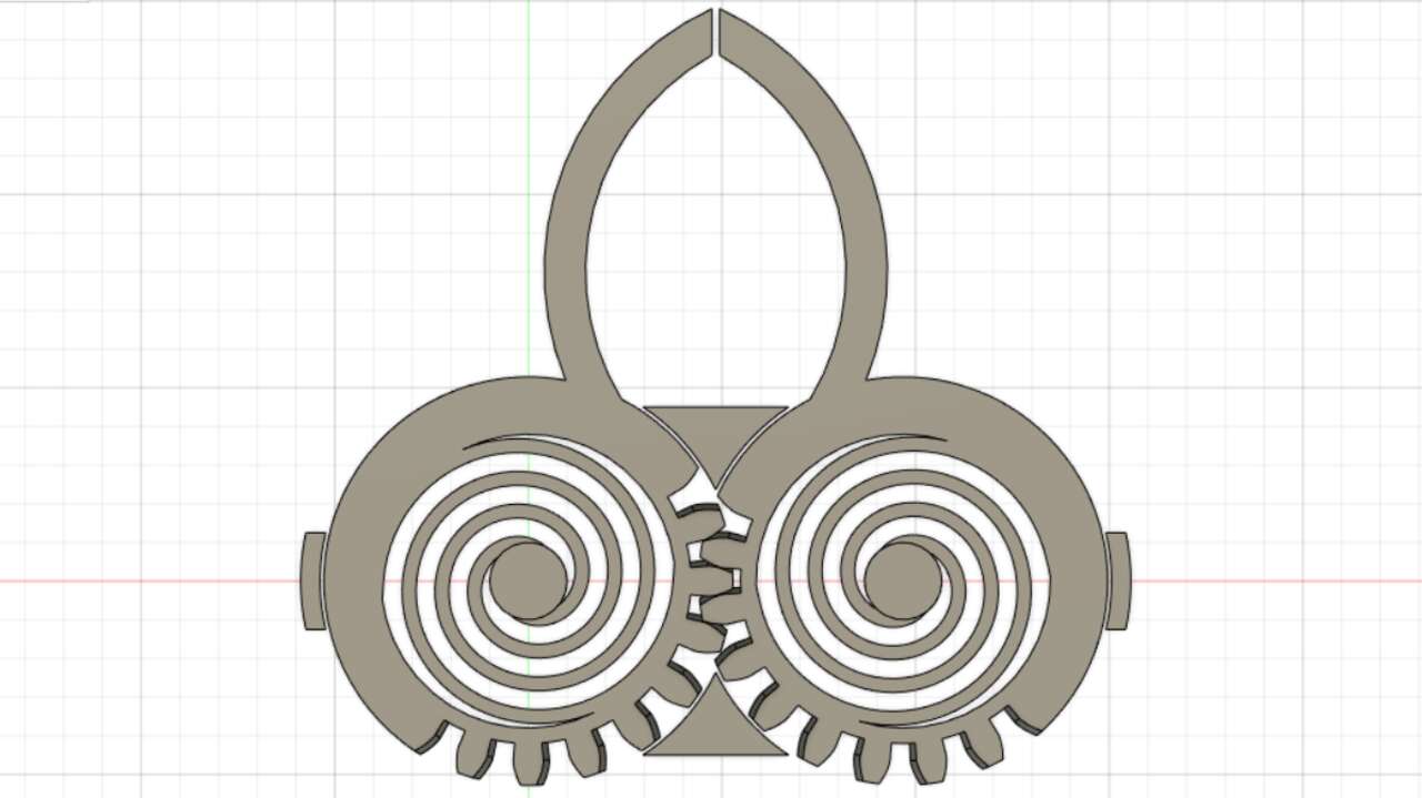
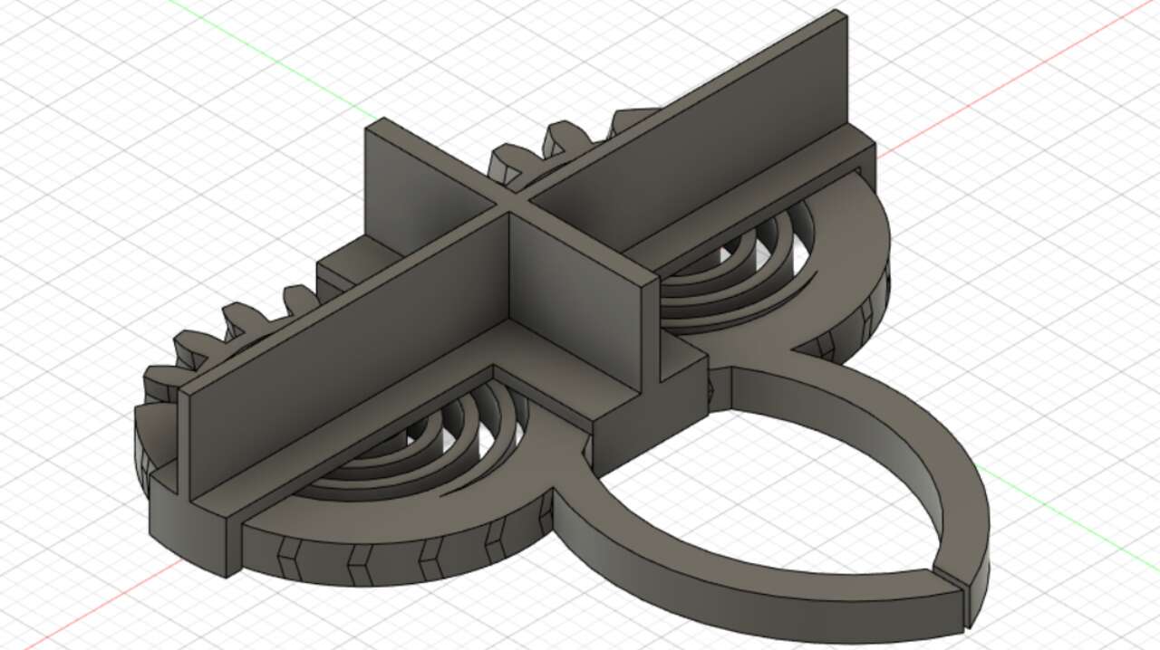
With the base for the holder, I draw a holder stick with a hole of 5 mm where the bolt enters knowing that I want to use a 4 mm bolt. Once the holder stick was made, I cut multiple semicircles along the gripper for a better grip as can be seen in the second picture.
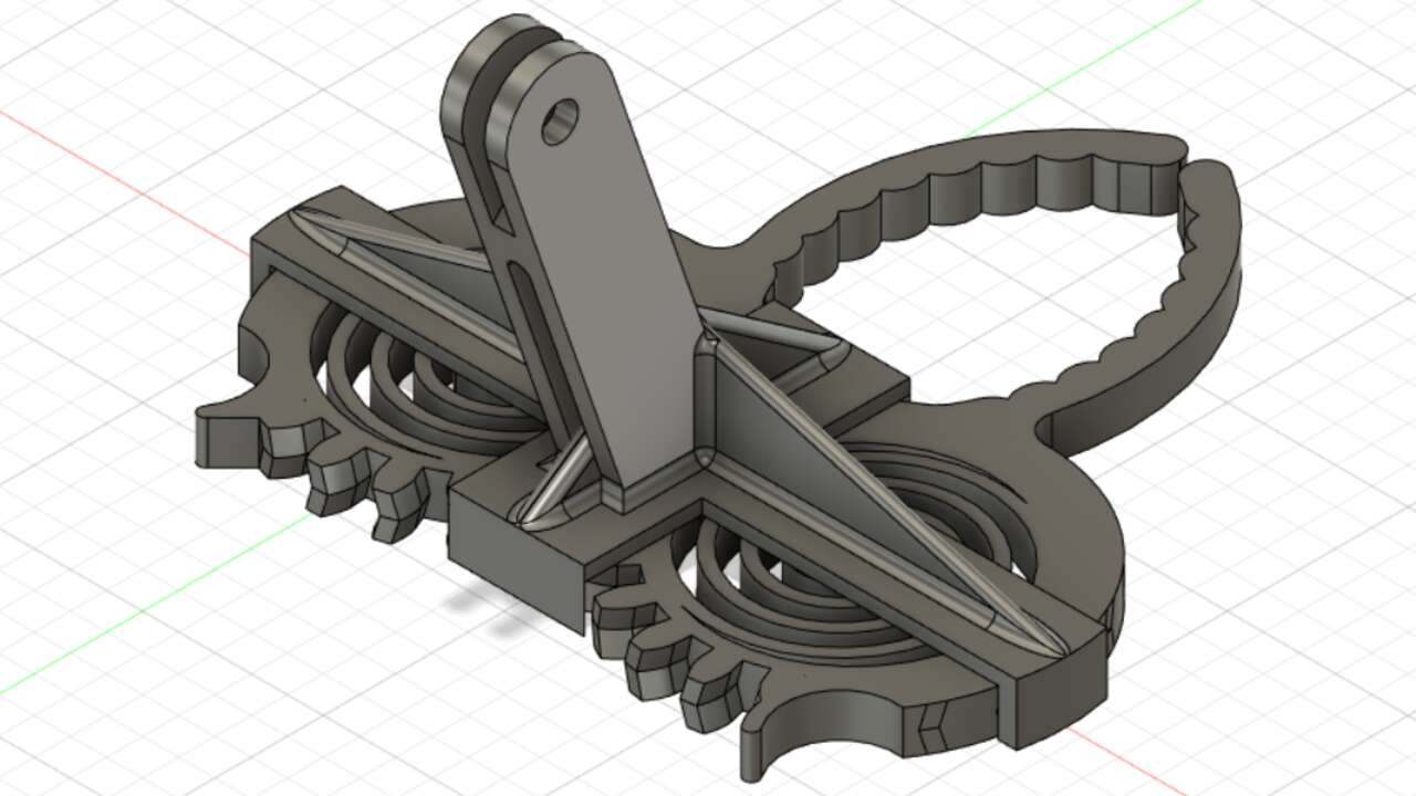
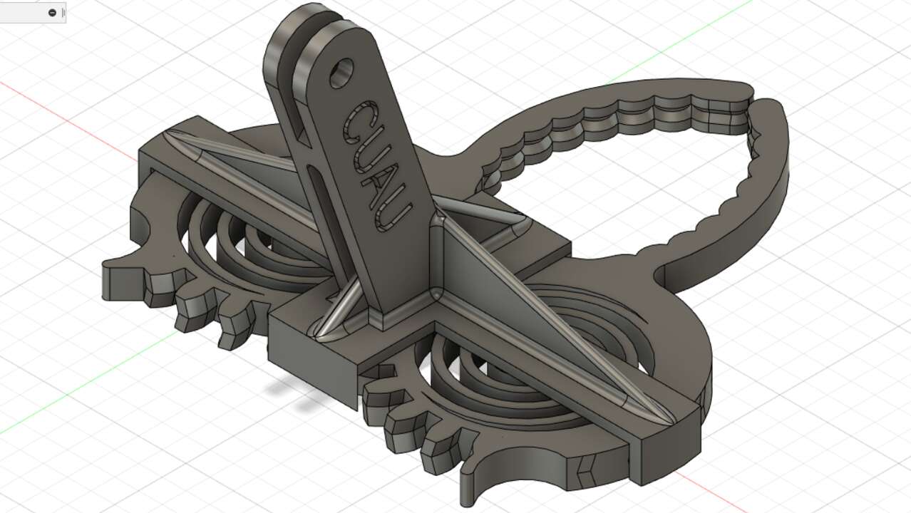
After the semicircles were cut, I create a slot along the gripper to hold the pcb on the middle of the gripper. Finally, I wrote my name on the stick.
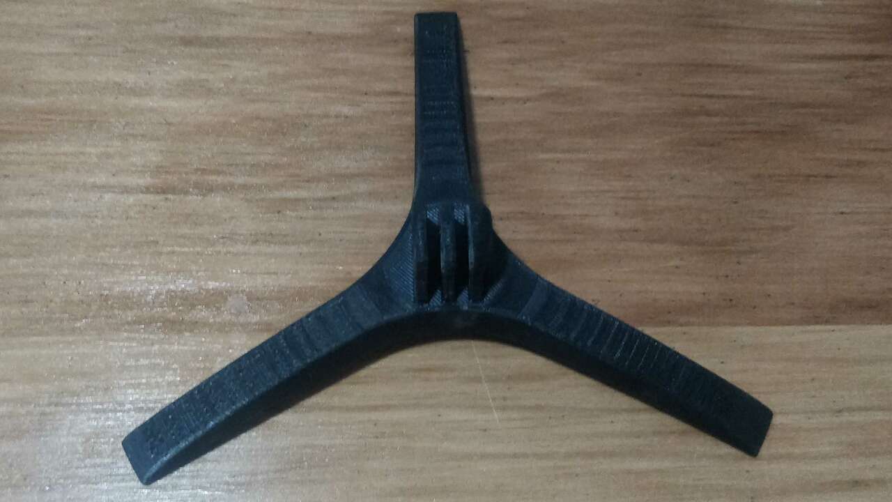
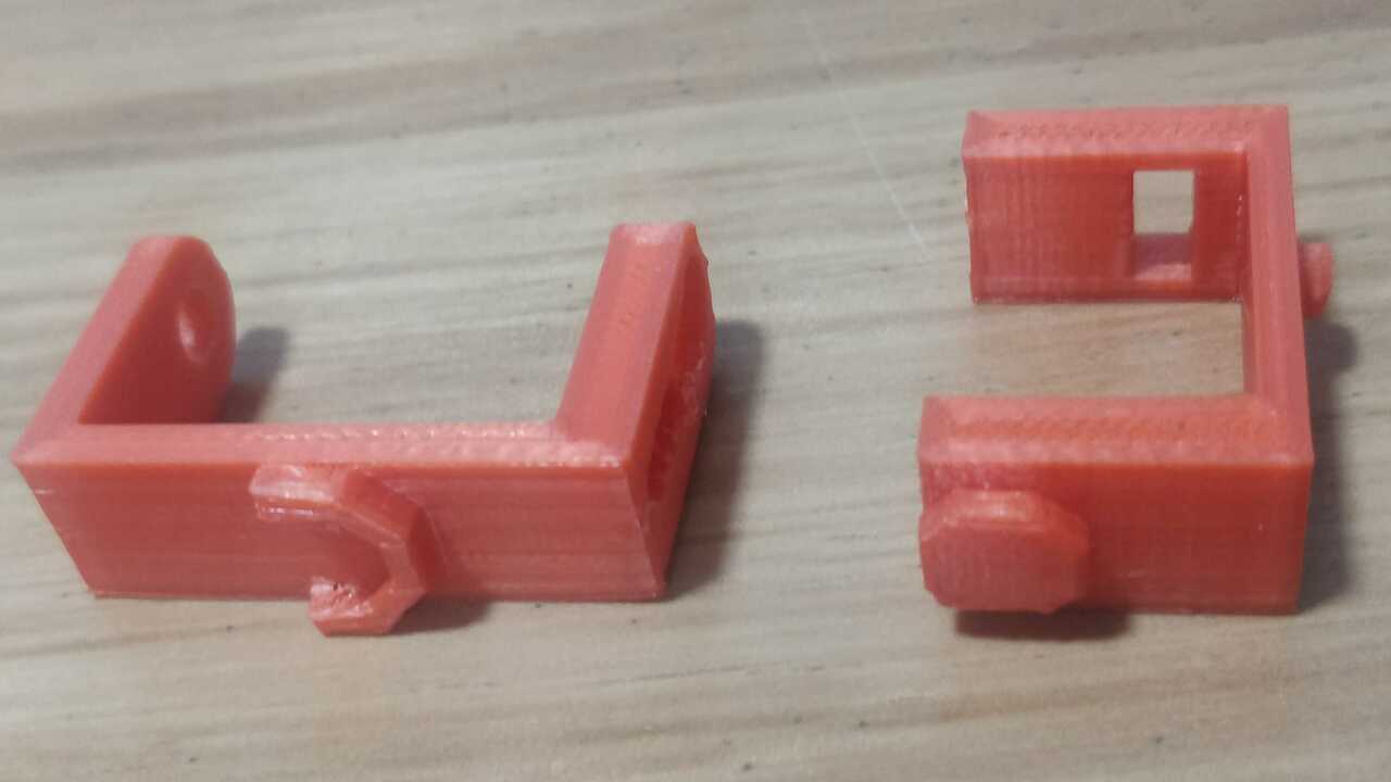
As well as the base, the gripper design was export to a stl file and later sent to the the 3d printer but this time the settings were changed a little bit for a better performance. The gripper was printed in ABS with 0.15 mm layer and 20% infill as can be seen in the next picture. The following pictures illustrate the manufacturing process of the gripper.

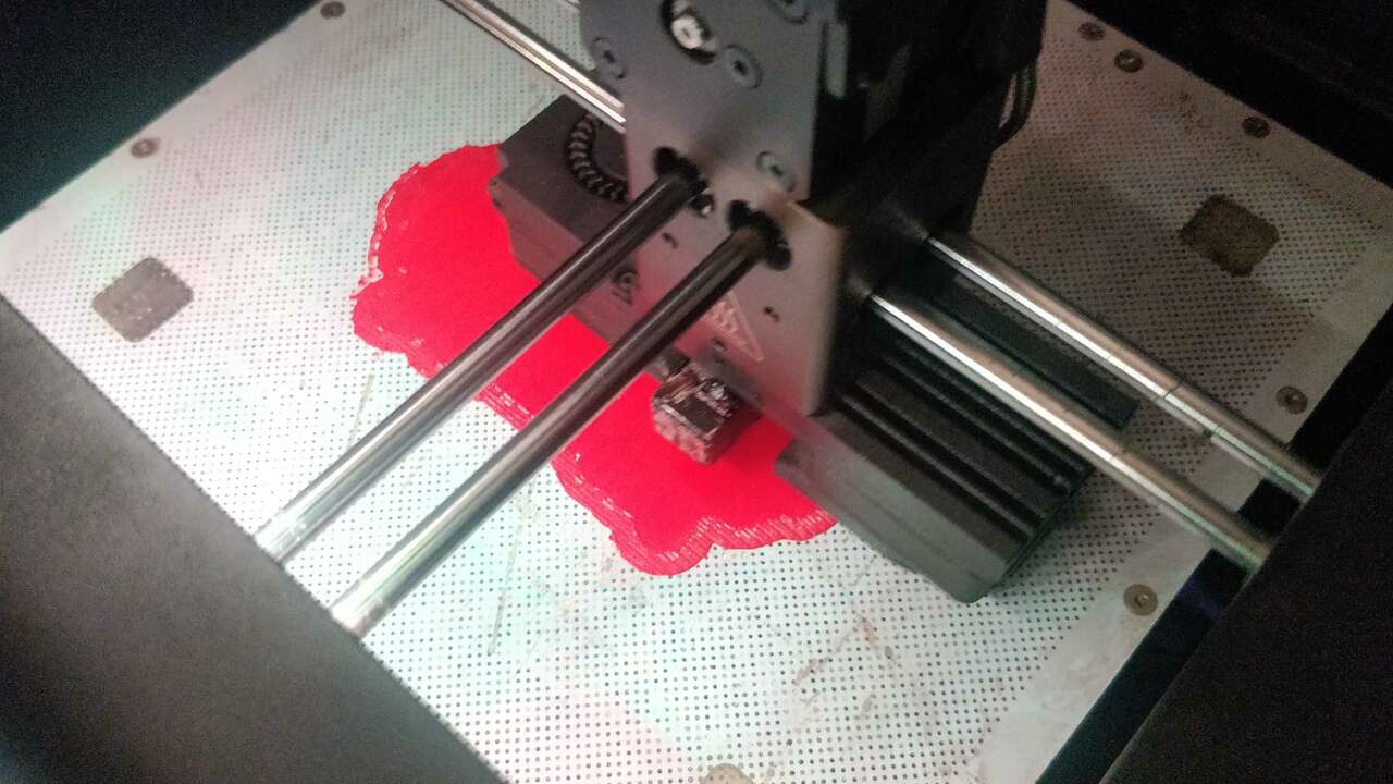
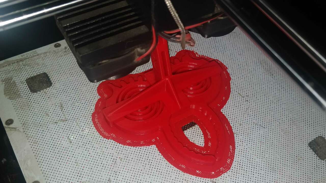
Here is a small video of the printing process:
After both pieces were manufactured, I assembled them with a bolt and a nut of 4 mm. The next video shows the final assembling and how it can hold a pcb really well.
3D scanning
3D scanning is a process of analyzing a real world object to collect multiple data and recreate its shape and sometimes the appearance. This process uses a non-contact and non-destructive technology that digitally captures the shape of the objects. The result of this process is a 3D model that can be help us to reconstruct, analyze, or simulate multiple scenarios and ideas. Nevertheless, there are different many different machines that can 3D scan objects and most of the time these machine use Laser 3d scanning, photogrammetry, or structure light scanning method to scan.
- Laser 3D scanning
- Photogrammetry
- Structured light scanning
This method capture the shape of an object through a laser light to obtain a 3d model of the real object. The scanner that use this method can only capture what is in its field of view. The laser is projected on the object from the device and a sensor measures the distance to the surface of the object.
This method use photographs to estimate the shape of an object. Since the method utilizes the parallax between several pictures, they must be taken from different points of view.
The structured light scanning method utilizes a projector that projects different light pattern on the surface of an object. Thus, the generated patterns by the object distortion is recorded to recreate the 3D object.
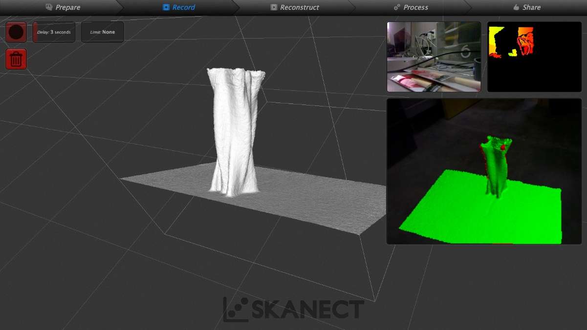
Kinect and Skanect
In the FabLab we have a kinect sensor and a software called Skanect which uses the kinect to 3D scan an object. To use the sensor you need to install the drivers and the software. The software has a free version which is limited but you can get good results.
Once the drivers and the software were installed, I executed the following procedure:
- Plug the USB and power connecto of the Kinect
- Open Skanect
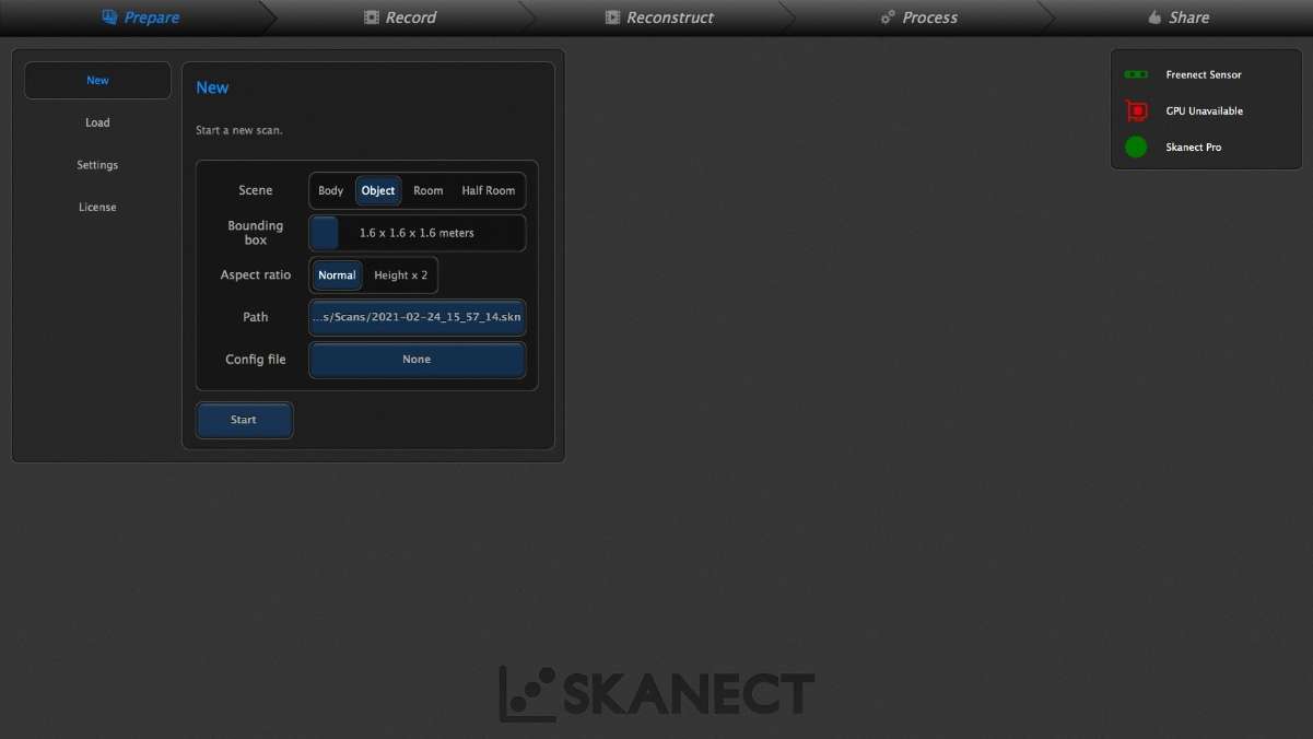
- Create a new scan
- Select object in Scene
- Set the dimension in Bounding box
- Click the Start button
- Now is time to take the kinect and move around the object to be scanned
- Try to move slowly and use the screen as a tool to know where you are
- Click the Stop button
- Move to the Process menu and select fill holes with the standard settings
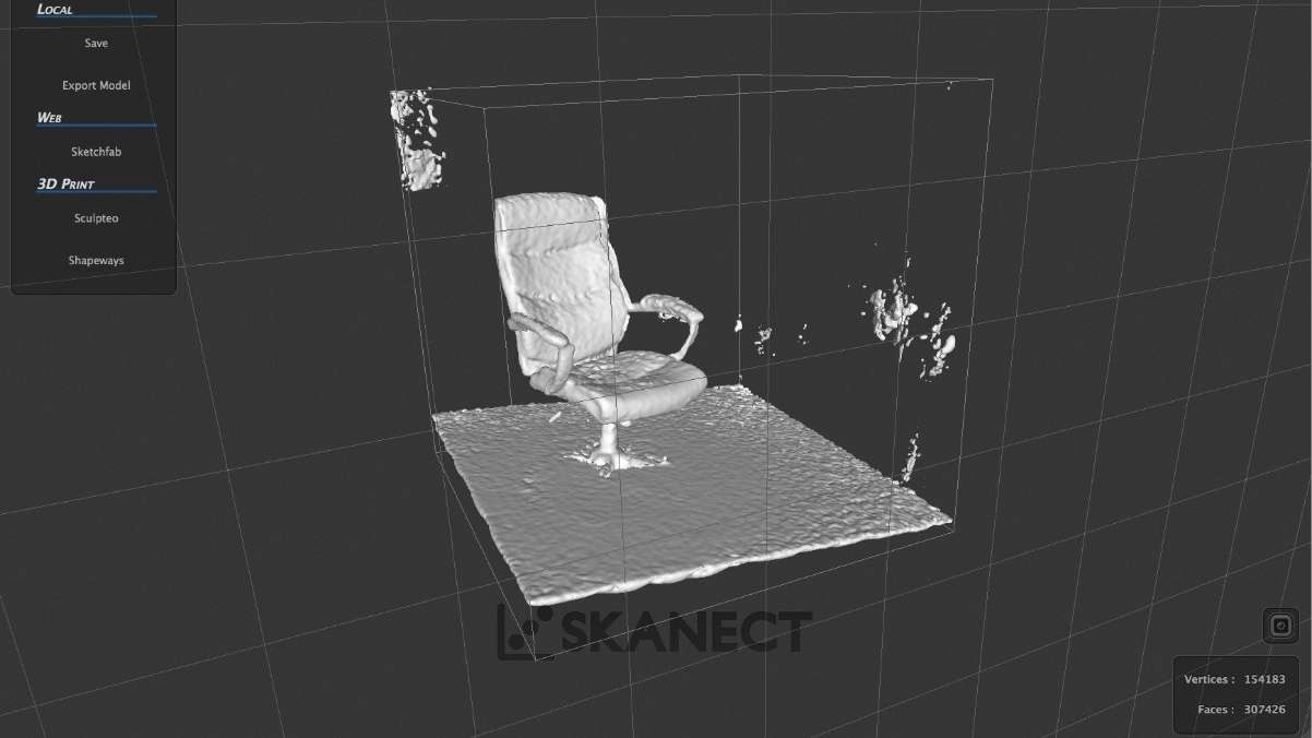
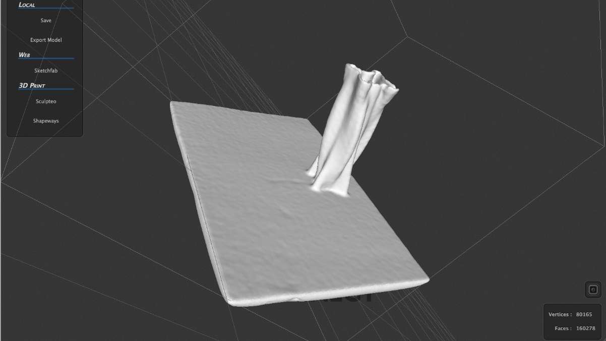
- Move to the Share menu and click on Export model
- Save it with any of the possible formats
The following pictures show the process previously explained for a better understanding.
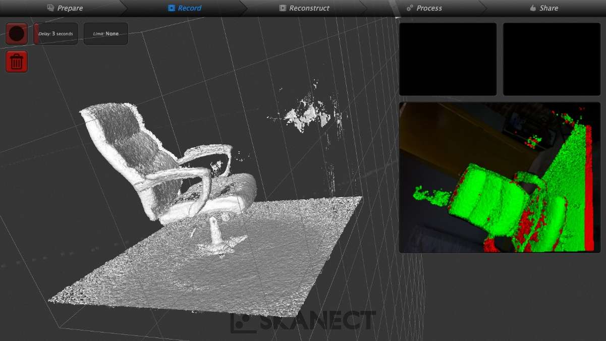
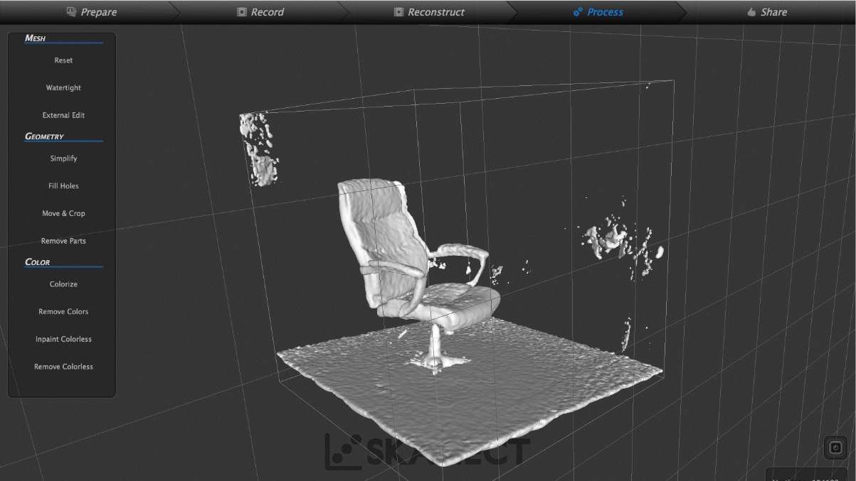
The final result along with a photo of the real object can be appreciated in the following picture
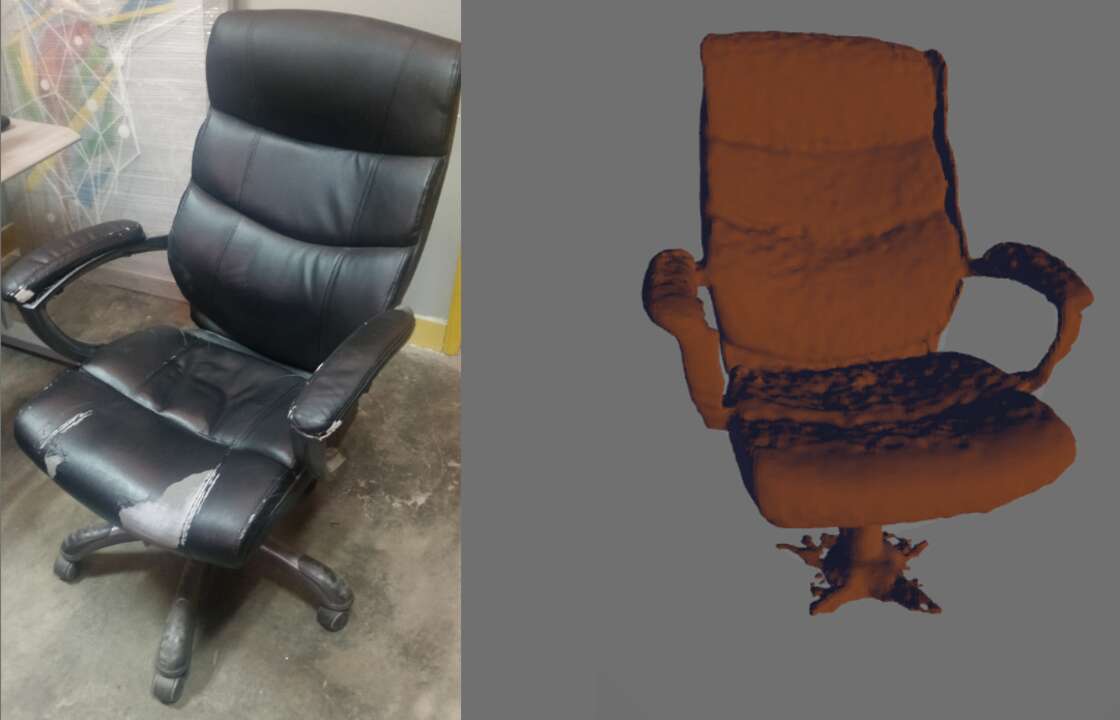
What I liked the most when using the kinect was that it is really fast maybe aroung 2 to 3 minutes and the interface is really friendly and easy to understand. I did not have to looke for any tutorial to use it and we can find a kinect aroung 50 USD which a really low cost for a scanner.
ReCap
I wanted to try out a program that one of my instructors recommended me. This software is called Recap and you can download it from here. Since I still have my student email, I was able to get the pro version free for the next year. I just sign up in Autodesk and they verify your account with the email. After that you can download it and activate with your account.
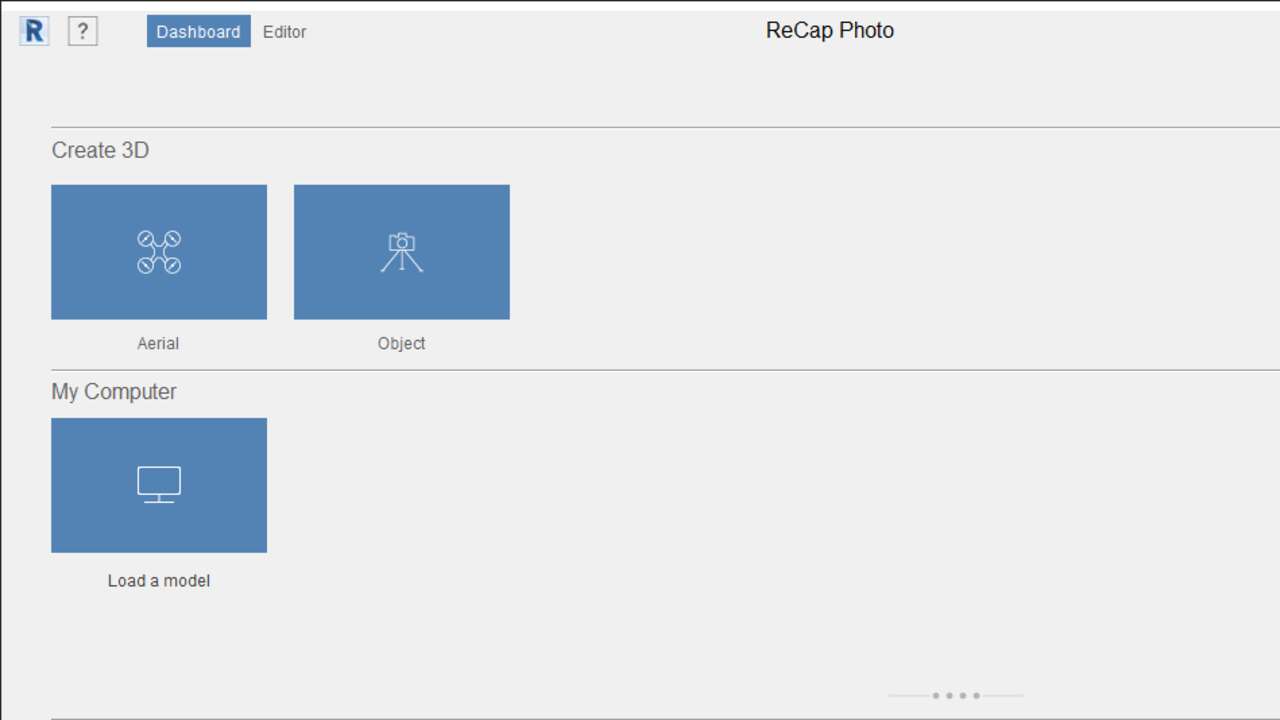
First, I took a bunch of picture of the model that I wanted to 3D scan. Later, I opened the software and I click on object under Create 3D. A new window will be shown and here you can drag the picture of the object or you can select the folder and the photos in your computer. Now, the software will created the 3D object just by clicking on the object name on My Cloud Drive
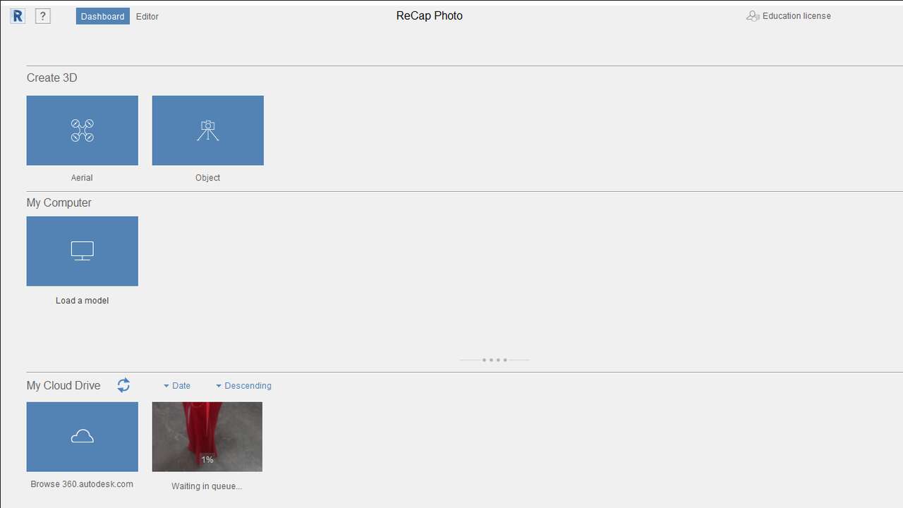
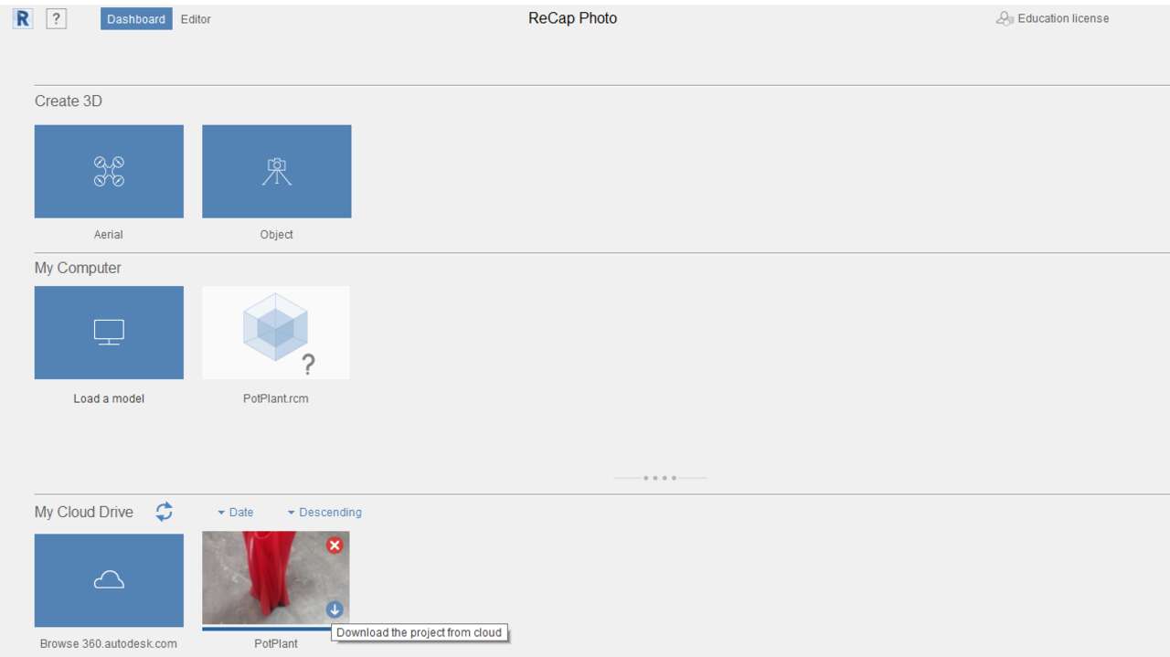
Depending on the pictures and the model, the software can take many hours. In my case, It took around an hour to be completed. Now to see the file you can click on the download button that is over the 3D object in My Cloud Drive. When you download the program a new file with an extension called .rml will be created. This file is an editable file where you can optimize the 3D object.
Comparing
Since I wanted to compare both scanning method, I decided to scan with the Kinect the same object that I used while testing the ReCap program. The process was the same that I explained early and the following pictures shows the initial screen and the final object with the Kinect
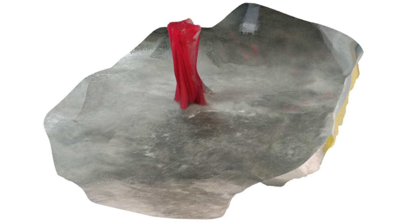
Once I 3D scanned the object, I used ReCap to erase parts that do not belong to the object and adjust the dimensions. Thus, I created an image that shows the real object on the left, the object created by the kinect on the middle, and the object created by ReCap on the right.
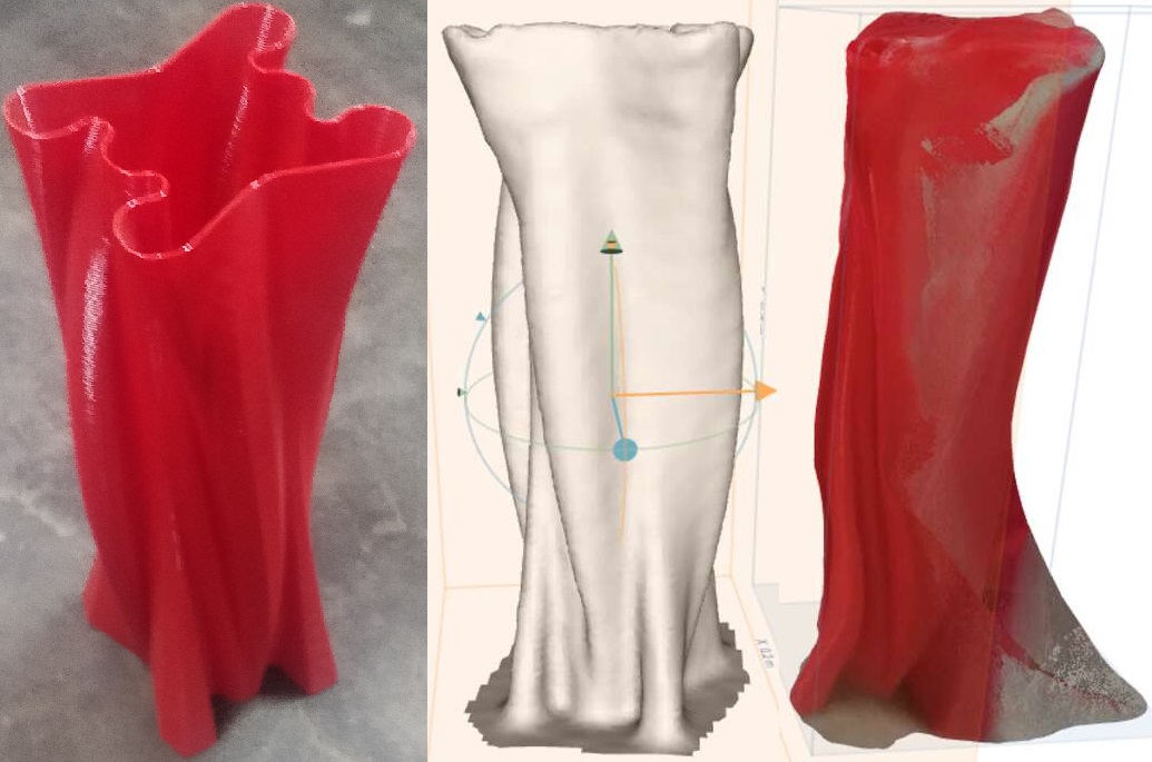
In conclusion I think that the Kinect with Skanect were the best option to scan an object. This method is faster and more accurate than ReCap with photogrammetry. Nevertheless, ReCap was really helpul to clean and fill the holes in the 3D file. I think that ReCap is mainly use to scan whole building since the geometry is easy and a laser or another method is impossible since you need to go aroung the building.
Final Project
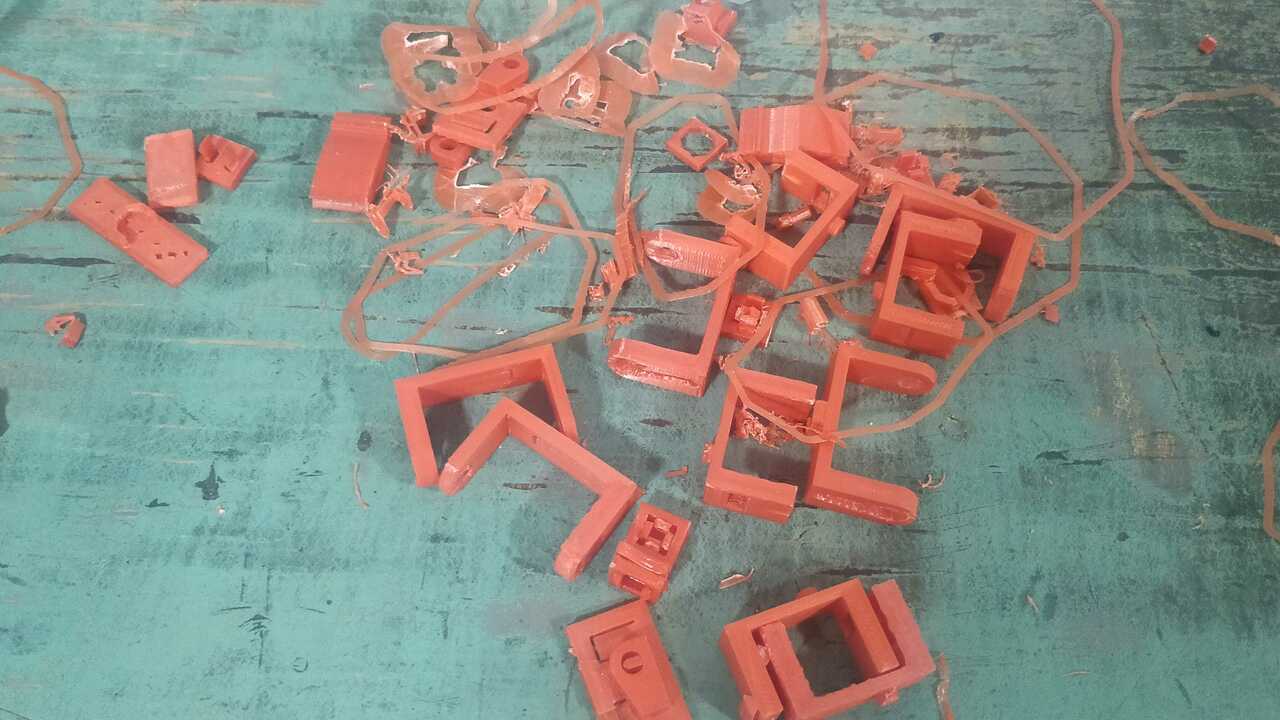
Finding the best clip and play system
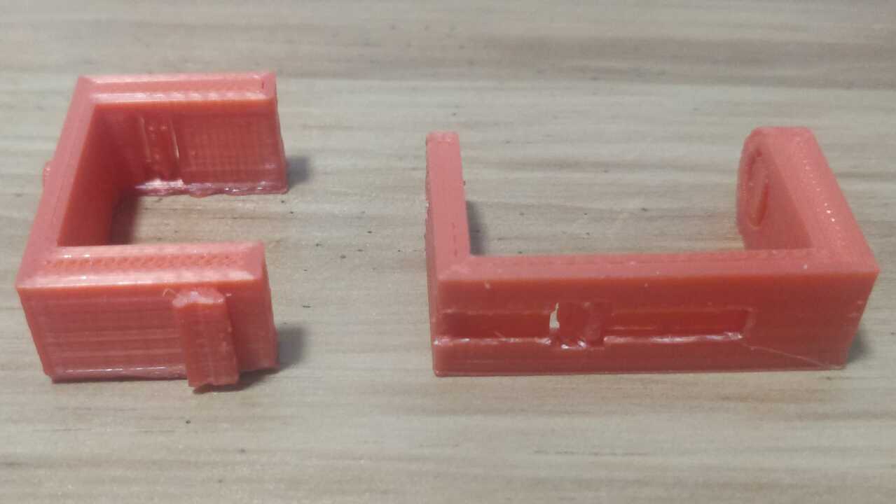
In order to create the first version of my robot, I 3D printed the drawn version that I created in Fusion 360 and that was presented previously on this page. Nevertheless, I realized that the joint was not strong enough to hold both parts and sometimes the female joint broke because it was to thin or the 3D printing was not so precise. Therefore, I created a second version that is shown on the right, where one parts must slide into the other and after it reached its destination a clip will comeback to the original position.
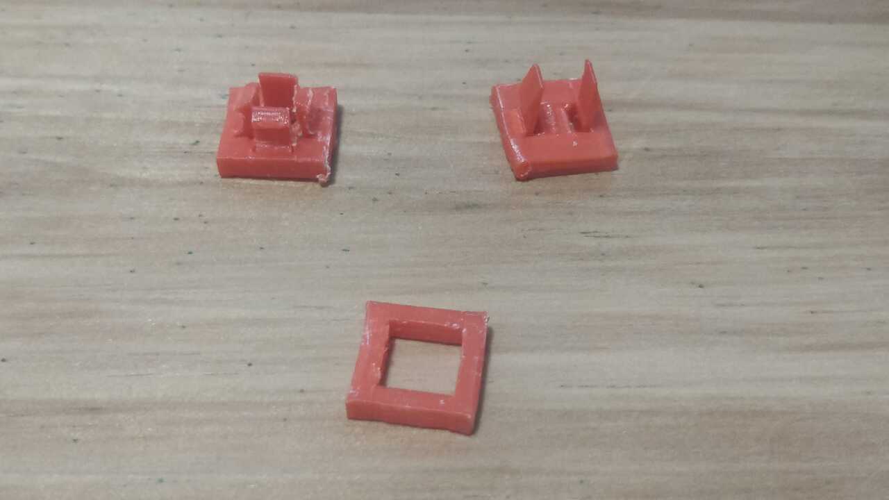
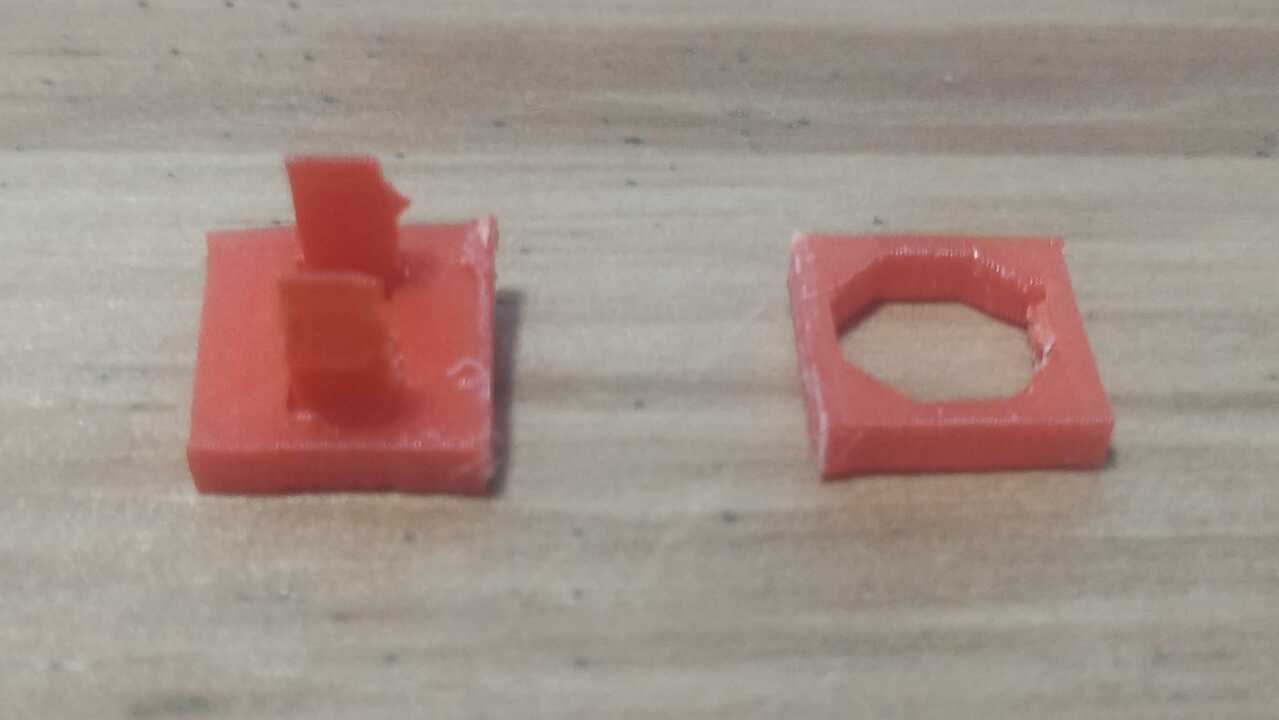
The only problem with the previous version was that I had to create different holder for the servomotors depending on the required assembled angle between servomotor. So, I created another two version that can fit into an square of 10 by 10 mm. Unfortunately, this version was not working as perfect as I wanted because sometimes it is required that you assemble two pieces together in a different angle that 0 or 90. Thus, I created a fourth version that instead of using a square, I used an octagon with a clip and an octagon shape to hold the pieces as much as possible.
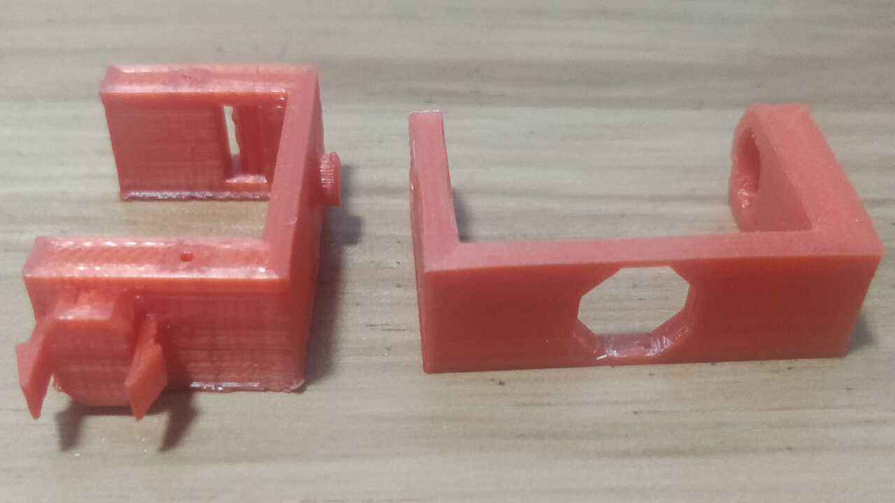
When I saw that the fittings was working as I planned, I proceed to create the last version of the servomotor holder and the C-profile that moves with the servomotor shaft. It is important to remeber that any good prototype requires many iterations to achieve the most efficient way or in this chase the most efficient shape.
The following video shows the multiple clips that I tested to see what was best for my robot
Files created
Useful Resources