Computer-Controlled Cutting
Laser Cutter
The laser machine where I developed my practices is the LZ1309-S-100 from Asia Robotica. It is a really powerful machine because it is adaptable to a 100 W or 120 W CO2 laser tube. A CO2 laser machine produces a laser beam in a sealed glass tube which is filled with a specific gas such as carbon dioxide. The beam is created with a high voltage that flows through the gas particles, increasign their energy and turning into a light beam. This beam is sent to multiple mirror until it reaches the focus len on the header. Another technology that this machines has is the up and down system to engrave or cut over materials that are in an assembly. The next figure displays a render of the machine:
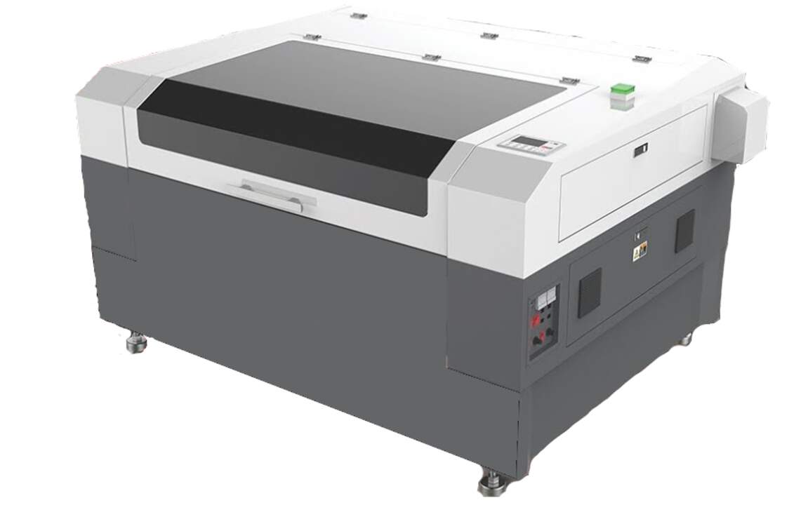
The following table shows the main specifications of the machine:
| Characteristic | Value |
|---|---|
| Model | LZ1309-S-100 |
| Working area | 1300 x 900 mm |
| Laser tube power | 100 W |
| Maximum engraving speed | 300 mm/s |
| Software | RD Works |
The supplier provided us with the following list of materials that can be cut and/or engraved with this type of machine:
| Material | Engraving | Cutting |
|---|---|---|
| Acrilic | ||
| Wood | ||
| MDF | ||
| Plywood | ||
| Textiles | ||
| Leather | ||
| Paper | ||
| PVC | * | |
| Glass | ||
| Stone | ||
| Steel | ** |
Kerf tests
Since, I am the only one that is taking FabAcademy in FabLab Puebla that is in Mexico, I will document all the group assignment in my own webpage. Thus, the first task to know better the machine was to obtain the kerf of the machine. The kerf can be defined as the width of material that is removed by a cutting process such as a laser cutting process. The kerf is really important when cutting parts on a CNC machine because we want to produce accurate parts with the most proximate dimensions to the final shape. For example, if we want to cut a 50 mm circle and the laser cutter removes 1 mm of material, then the resulting circle will have a diameter of 58 mm in case the kurf is not compensated. So the radius of the actual tool path must be 0.5 mm bigger in order to compensanted this kerf.
Now that we learned that the kerf is important to have accurate parts, we need to estimate the kerf of the laser machine that we will be using. To obtain this value, I machined the following sketch to compare the real measurements versus the expected measurements.
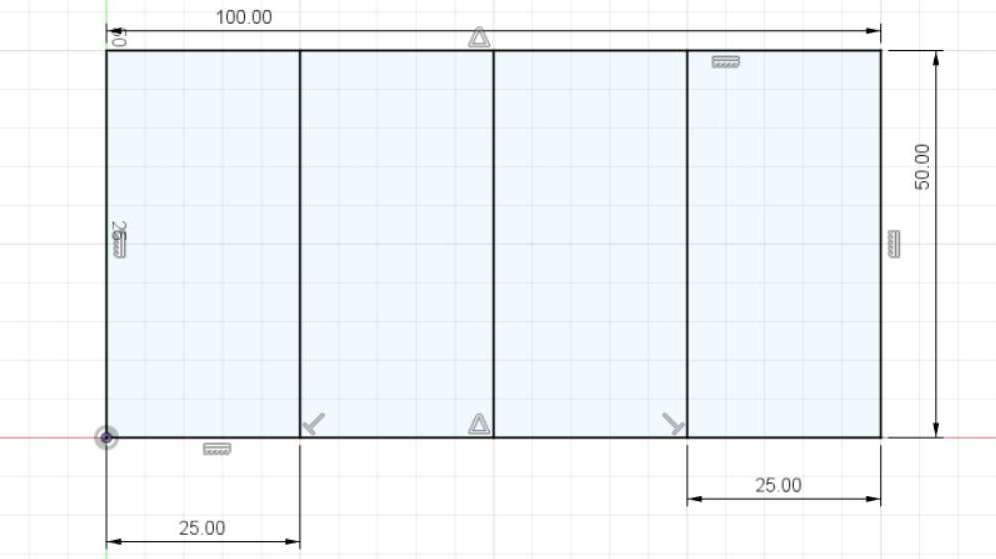
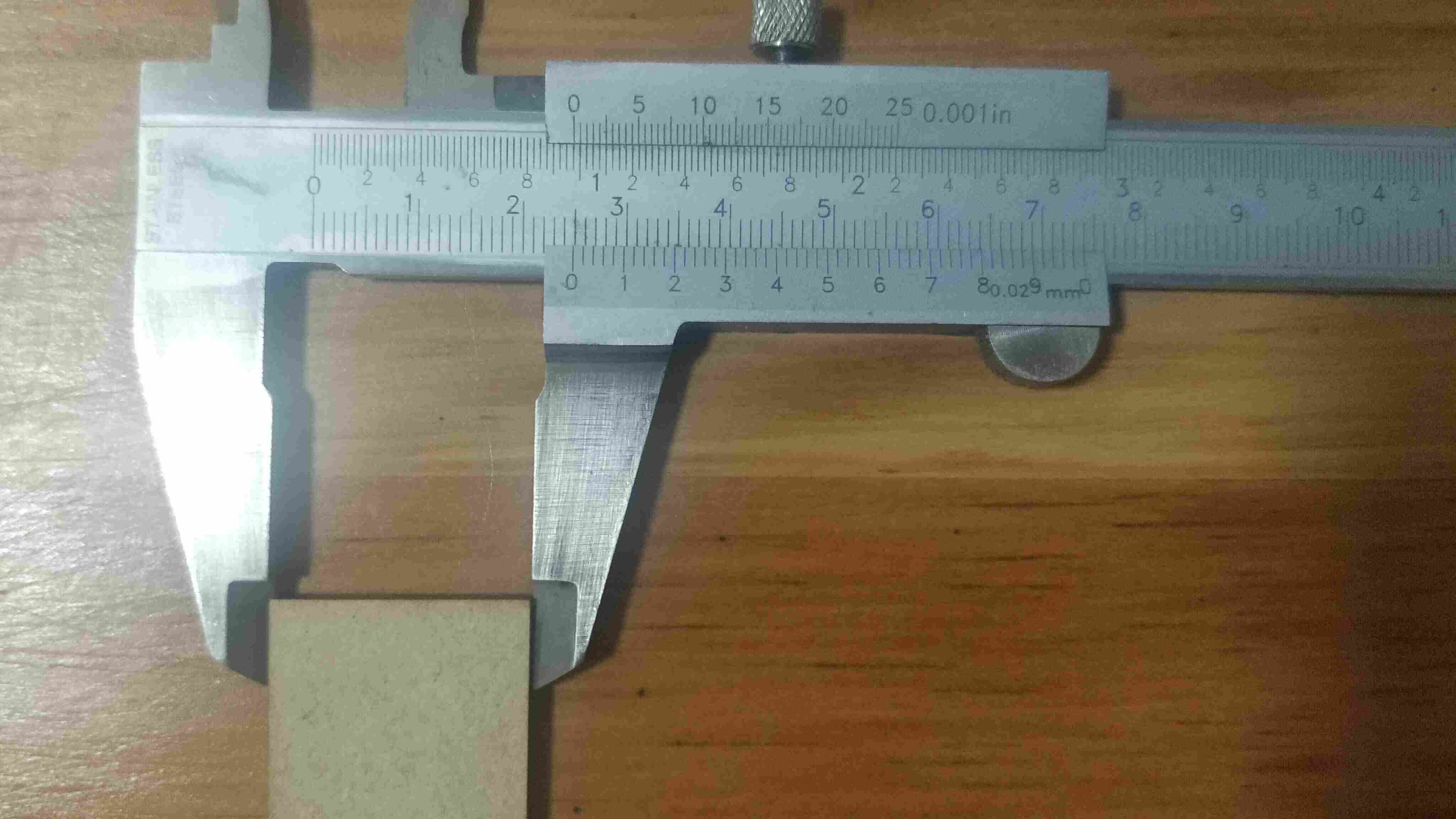
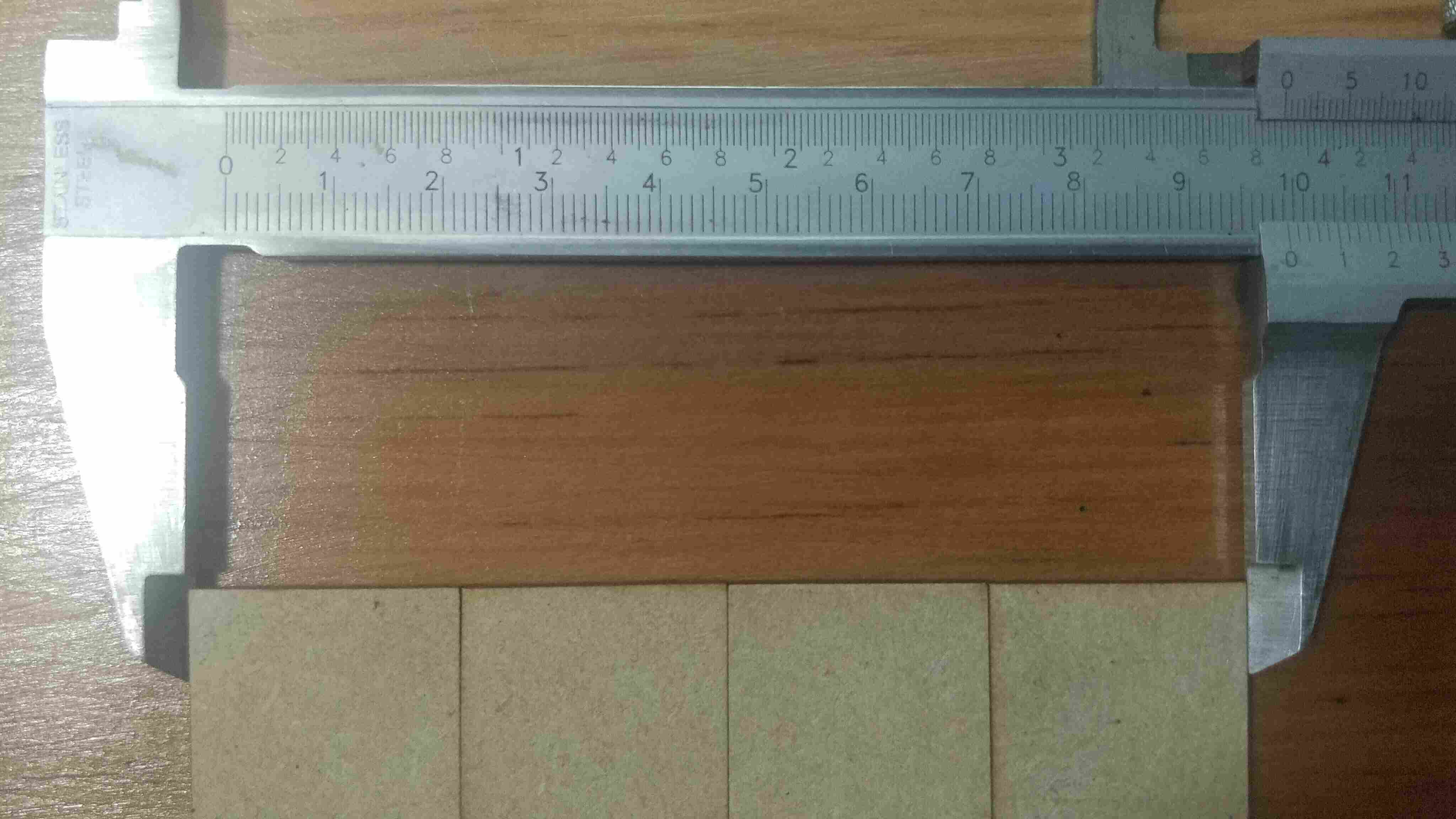
The experiment was divided in two tests, the first test is to measure a single rectangle of 25 x 50 mm and the second test was to measure the four reactangles together as it is shown the the images below.
The kerf of the first test can be calculated simply by substracting the real dimension to the expected dimension, while the second test must be the same subtraction but the result must be divided by 4 because the lines in the middle are considered as the complete kerf while the outside lines are the kerf radius.
| Test | Calculation | Kerf |
|---|---|---|
| Rectangle of 25 mm | 25 mm - 24.8 mm | 0.2 mm |
| 4 rectangles of 25 mm | (100 mm - 99.2 mm)/4 | 0.2 mm |
Engraving and Cutting tests
The initial experiment was a card of 100 x 50 mm which I used to compare the different engravings that can be produced by the CO2 laser machine. The idea is to vary the power and the speed in order to produce different engravings on the material. The laser machine uses the program RD Works developed by Ruida ACS. This software requires a .dxf, .plt or .ai file, once the file has been imported I proceed to select different layers for the engraving process and another one for the cutting process. The FabLab has recommended settings to cut MDF of 3mm which are 100% power and 30mm/s. While the recommended settings to engrave are 30% power and 300mm/s.
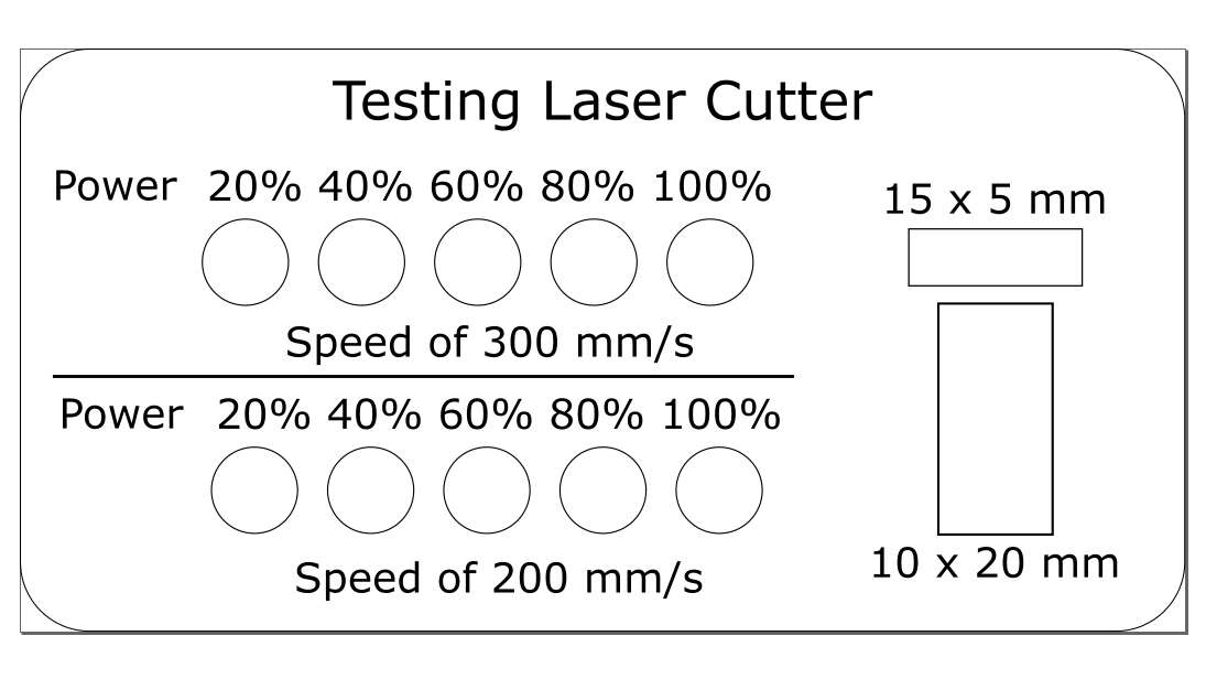
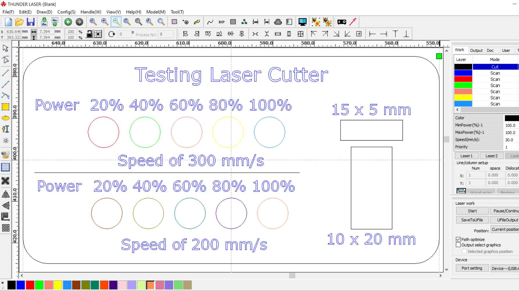
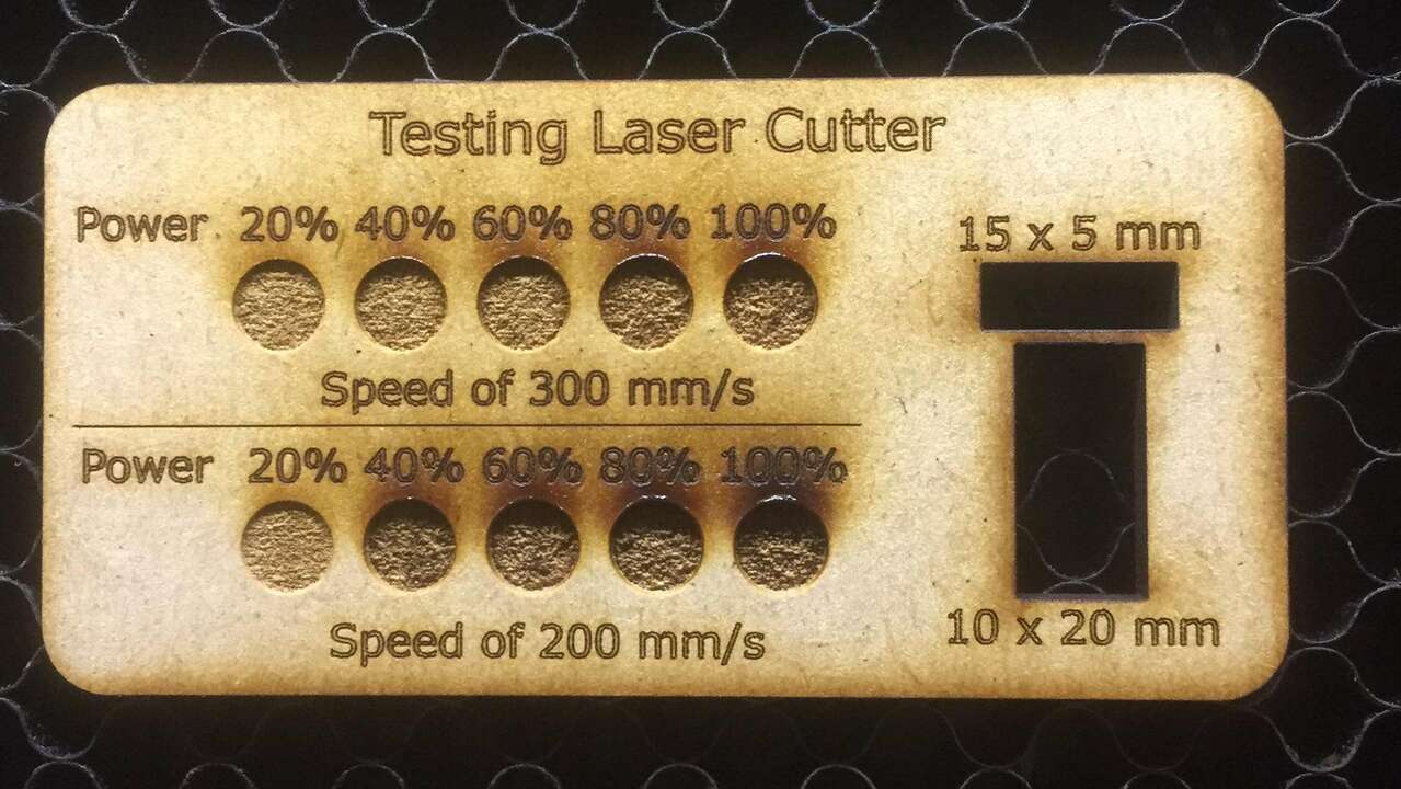
The following picture shows the final result of this first experiment, where can be seen that the darkest engraving is when the speed is of 200mm/s and 100% power while the brightest engraving is when the speed is of 300 mm/s and 20% power.
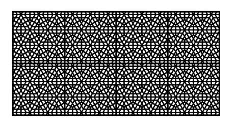
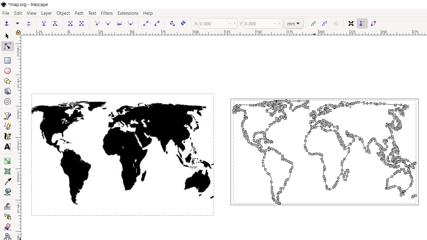
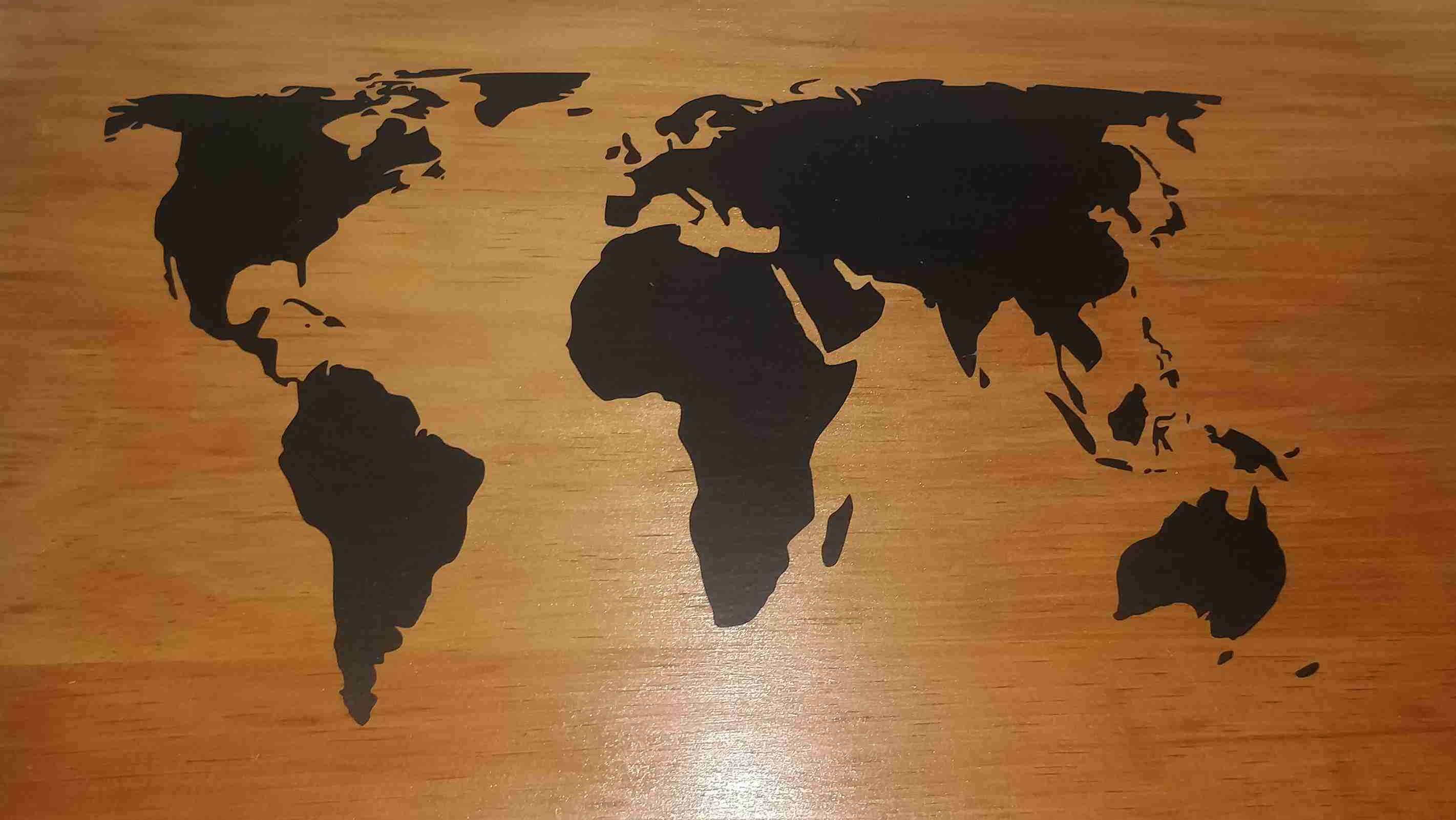
The next experiment was to analyze the precision of the laser when it must execute small cuts. I wanted to fusion a lattice inside the world map to cut small holes inside each contry and engraving the boundaries of each continent. Therefore, I started looking for lattice patterns that I liked to trace them and create a vector in Inkscape. Once the vector was created, I multiplied it to create a bigger pattern. Inkscape has a function to fusion multiple vectors into a single vector and it can be found in the path menu on Union.
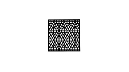
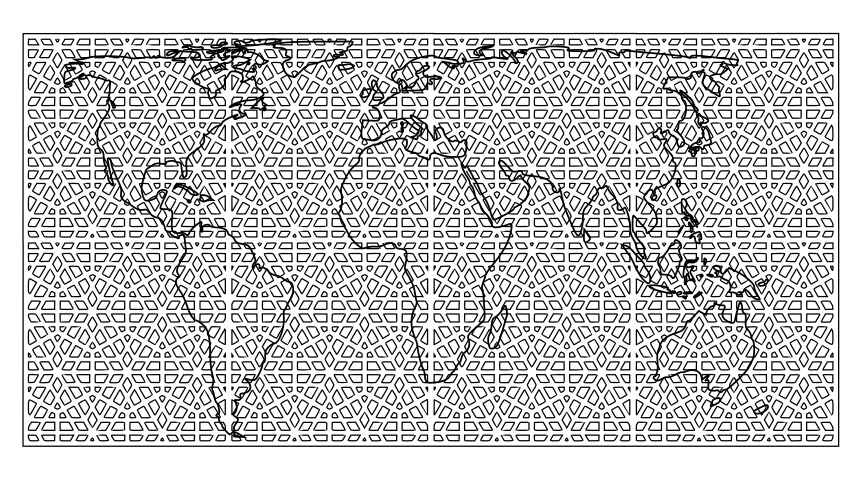
After the big pattern was fusioned, I overlaped the pattern over a world map. Later, I created a vector with the intersection between both vectors with the difference function that is under the path menu in Inkscape.
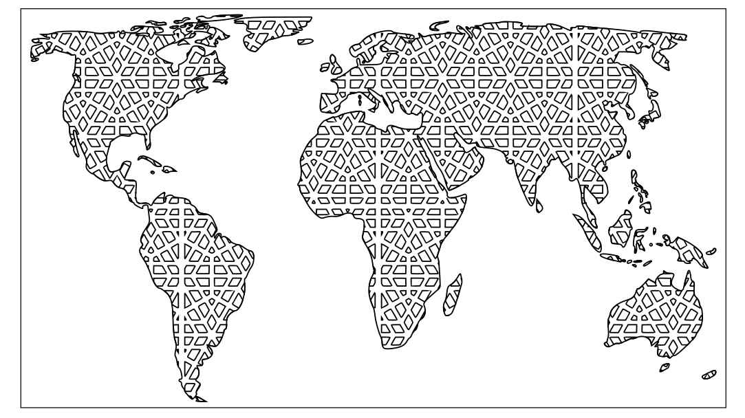
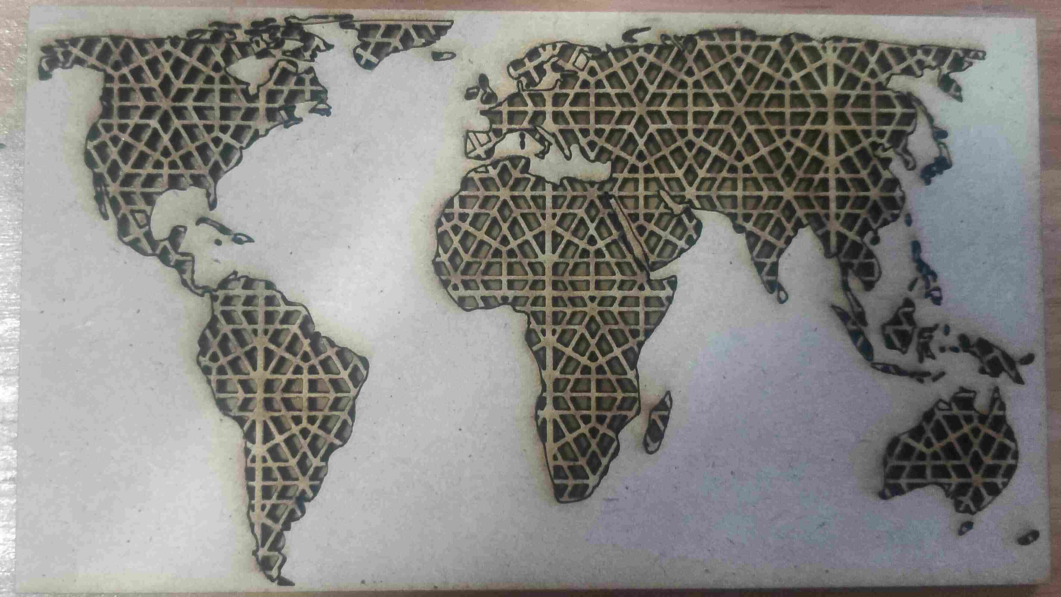
Like the previous experiment, I exported the created vector to RD Works and send the file to cut in a 3mm MDF with power of 100% power and speed of 300mm/s. The final result is shown in the following image:
Parametric Construction Kit
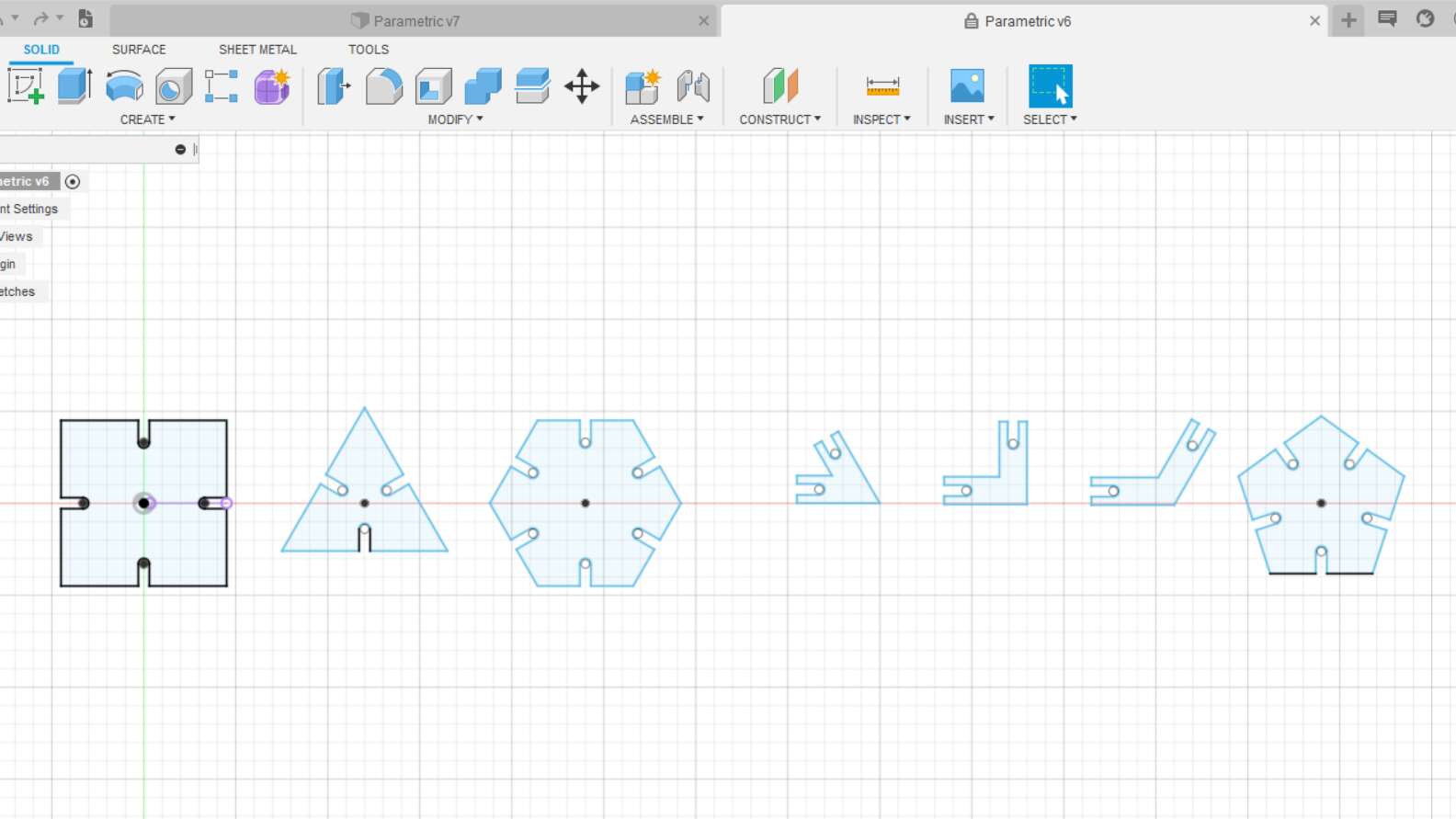
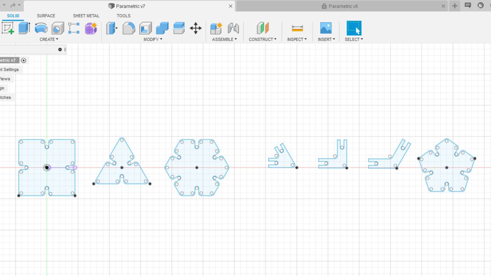
Once I practiced with the CO2 laser machine, I proceed with the development of a parametric kit that can be adapted depending on the material thickness and the kerf. Initially, I used Fusion 360 to create multiple geometric figures (Triangle, Square, Pentagon and Hexagon) as well as connectors of 30, 90 and 120 degrees as the following picture shows:
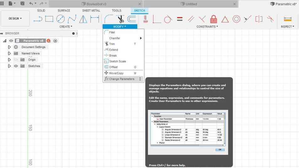
At this point is a normal design in Fusion 360 where there are no dimension lines but there are constraints. The next step is to declare all the parameters that our parametric design will use. Thus, in Sketch go to Modify and Change Parameter as the picture above shows:
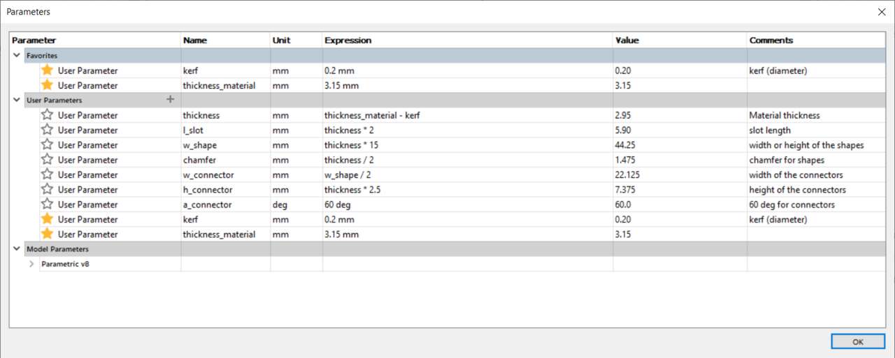
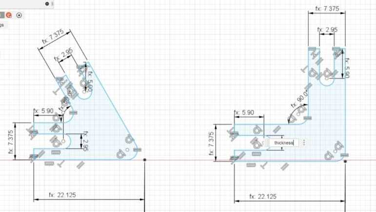
A new window showed up and I declared the parameters that the shapes need. These parameters depend on the material thickness and the kerf that was previously estimated. The equation that each parameter use is shown in the following picture:
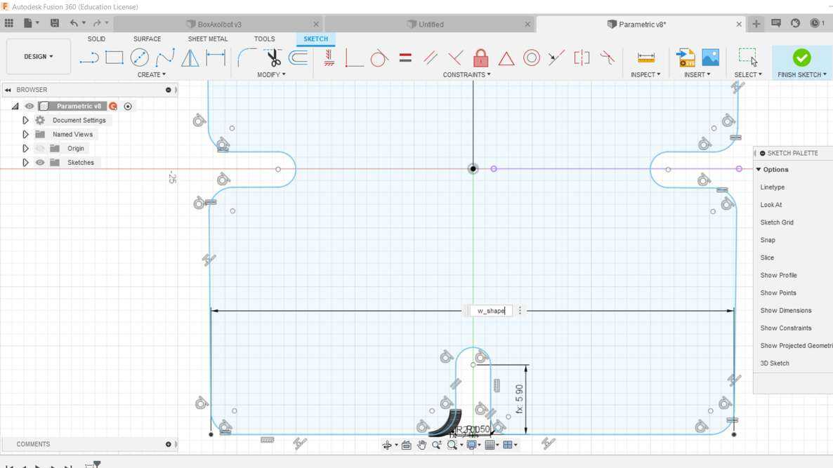
When all the parameters were written, I proceed to add the sketch dimension to each line where is need it. It is important to note that instead of writting the dimension value you must write the parameter name that was declared in the previous window as the next picture shows:
At the beginning was a little bit difficult to understand how the program and the parametric design works but later you get use to it. Then, the only thing that is left to do is to set every sketch dimension until the whol design in parametric.
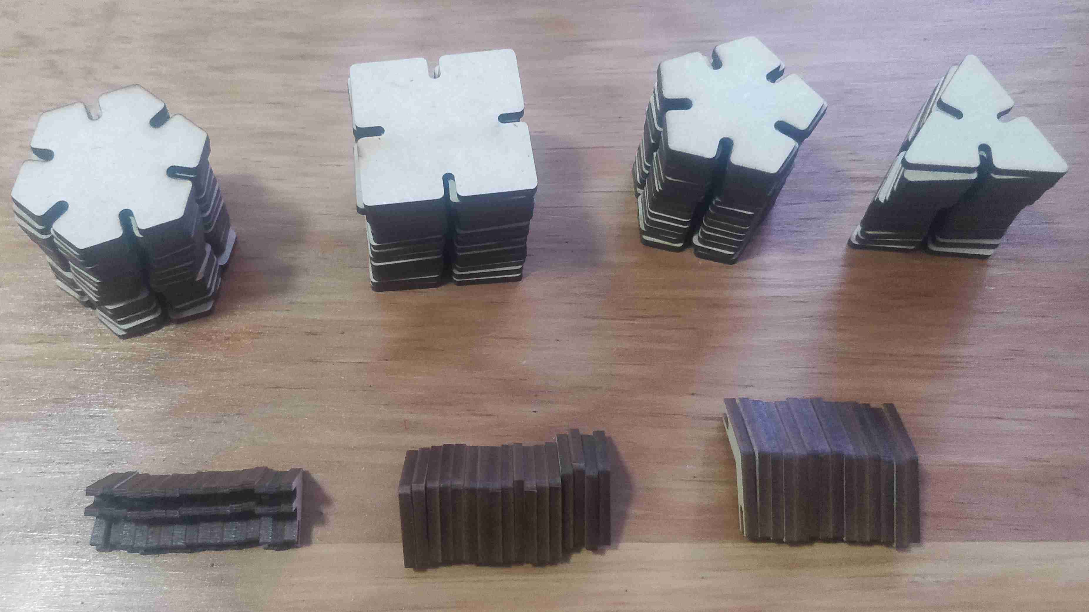
Before I created multiple figures, I decided to send a few figures to see if they fitted as planned or if there is a need to change the values. The following picures shows the cuts of the laser cutter and a first attempt to assemble some parts. Nevertheless, when I was assembling an object I realized that there was a need for a chamfer or fillet because the assembling process with multiple parts it was difficult.
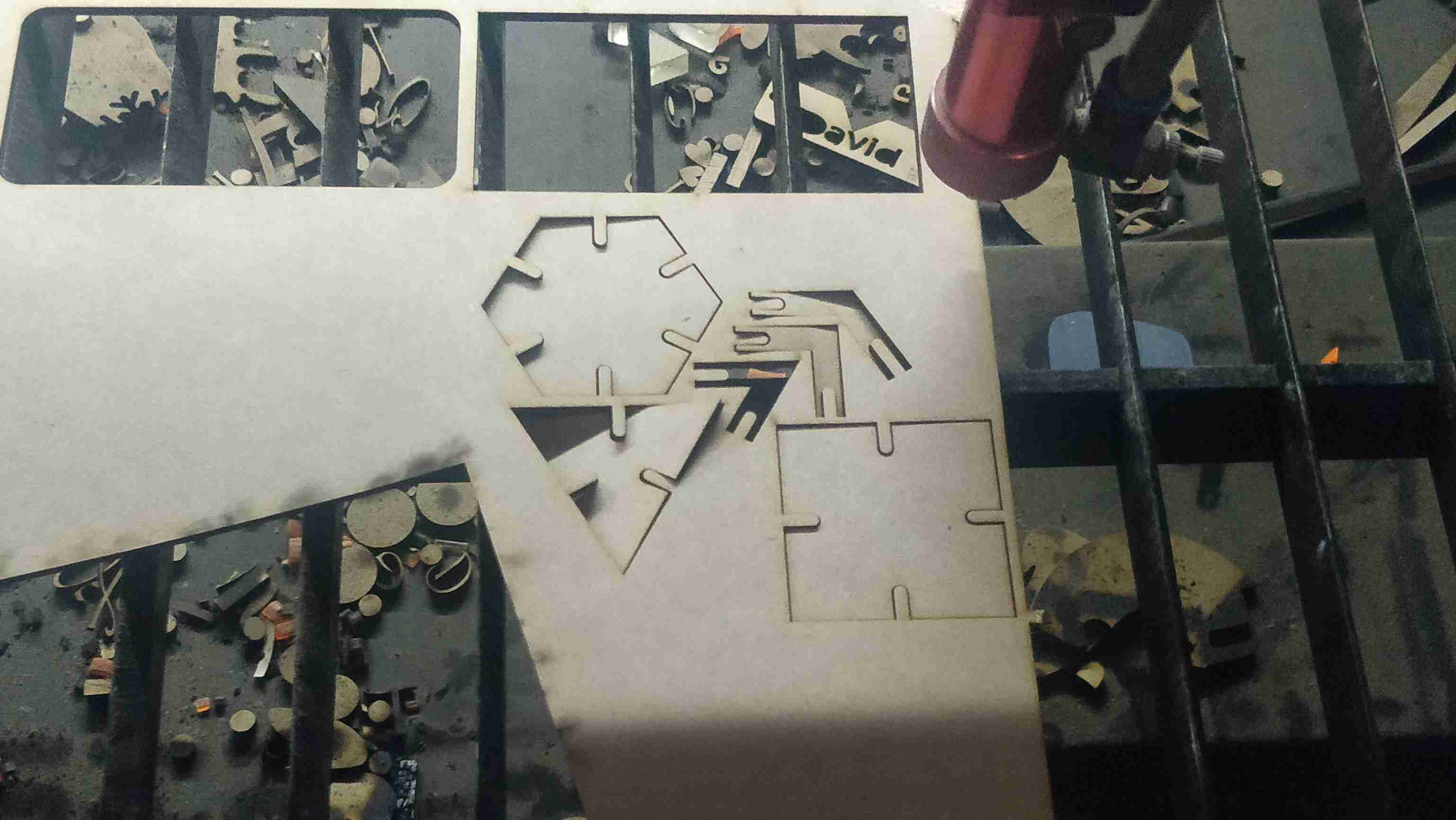
Therefore, I added a fillet in the corners of the main shapes to make easier the assembling process of the construction kit. After the fillet was added, I exported the dxf file to RD Works and I sent multiple figures to be able to create somes 3d objects.
Here I show an small video when the construction kit was being cut.
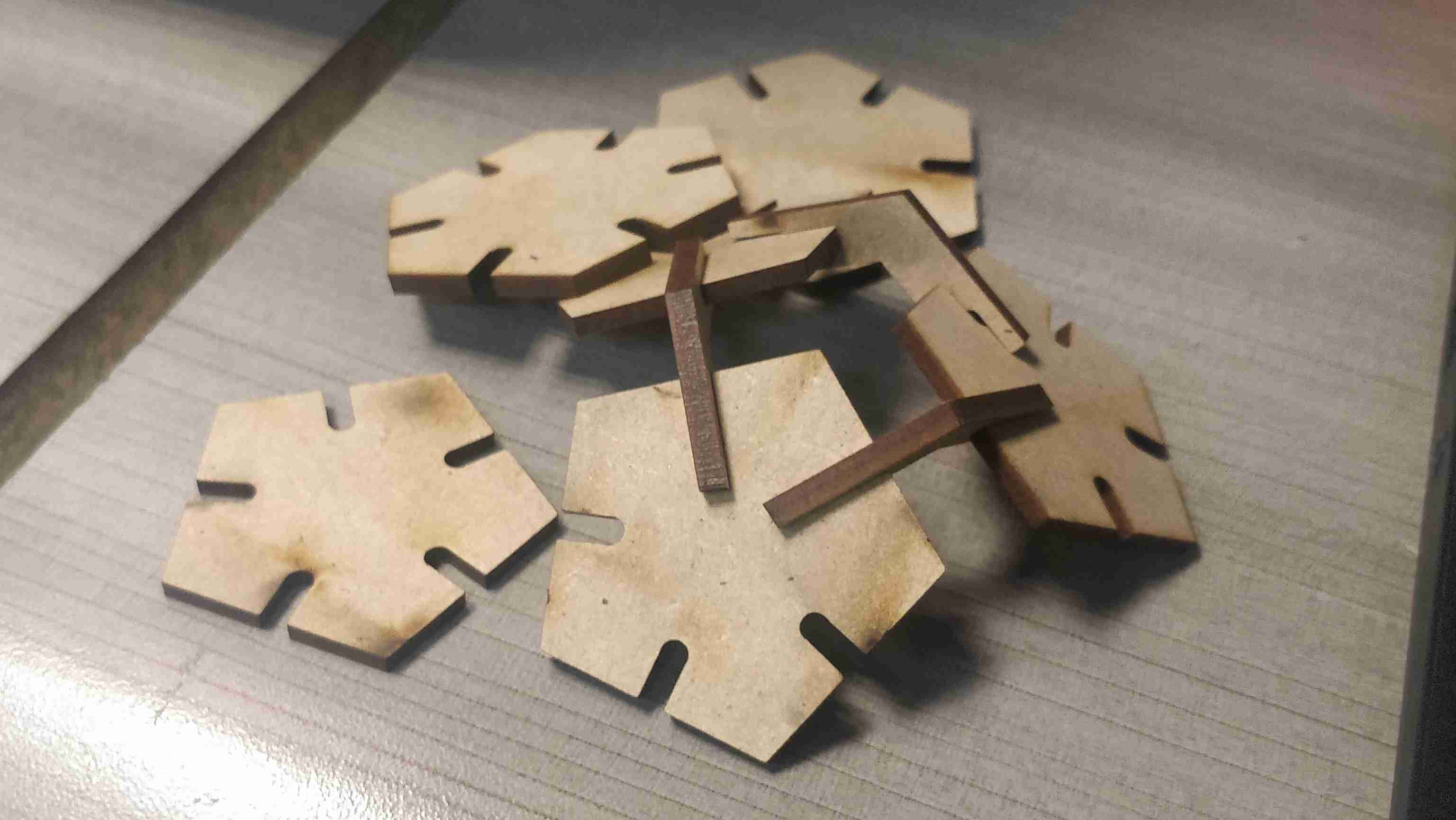
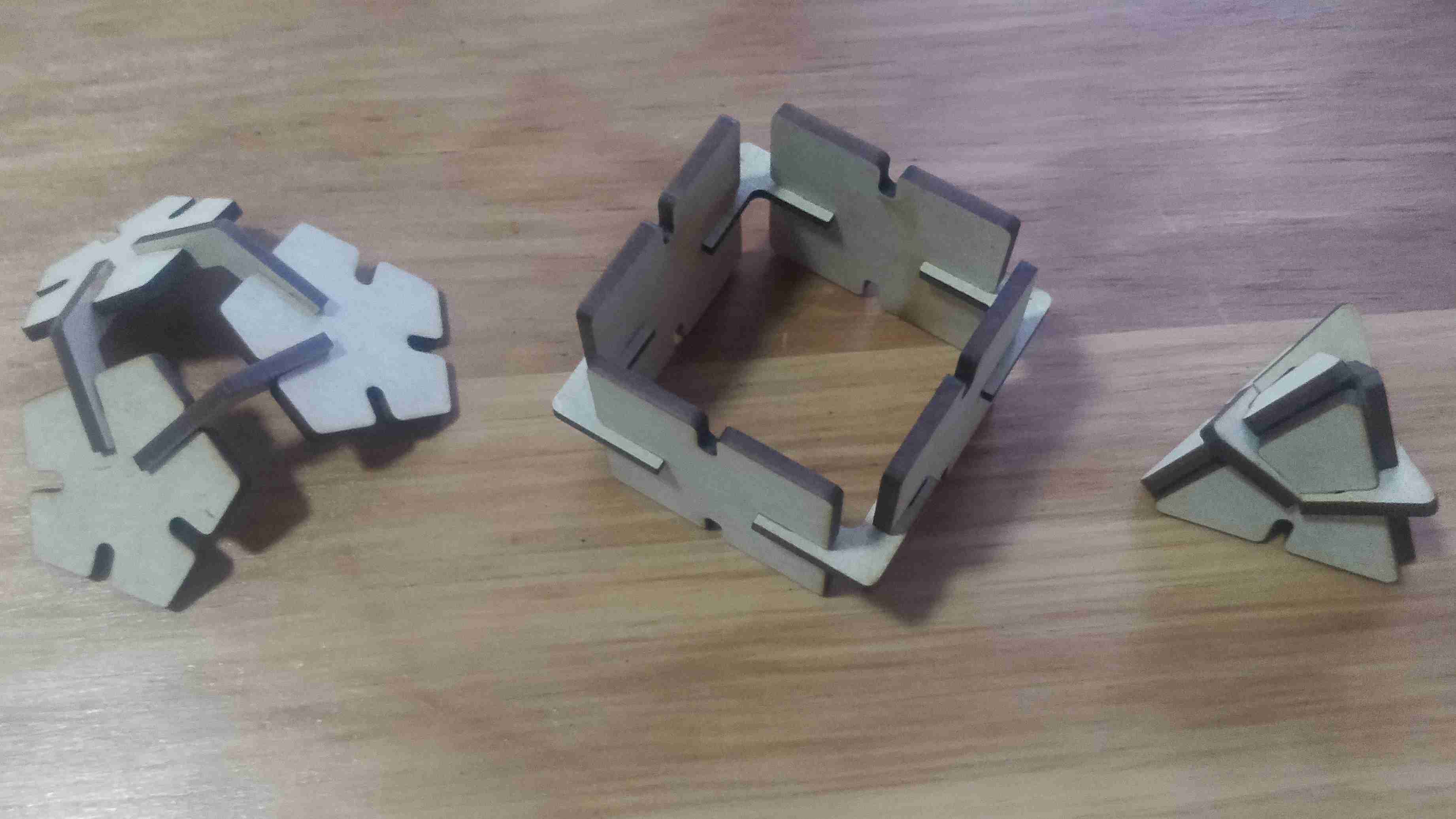
After I cut all the pieces, I started assembling some of the figures that I could think of. At this moment I was not having enough imagination but the picture below shows the first creations
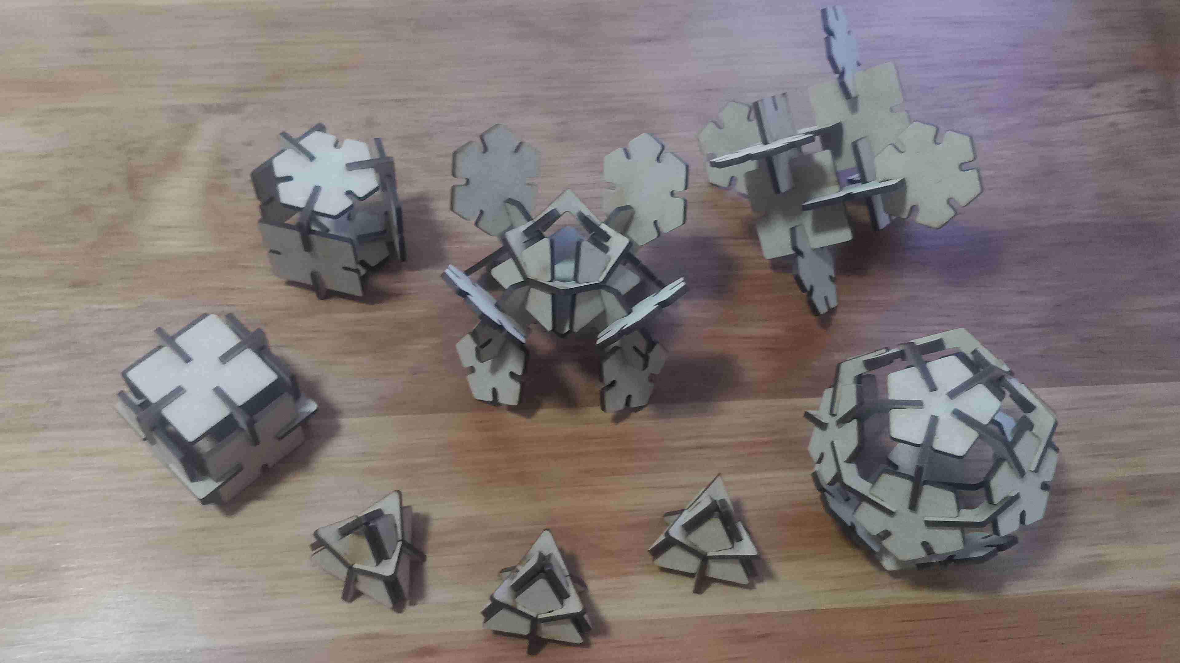
Once I got used to assemble the objects, I created more complex 3d objects like the ones show in the next picture.
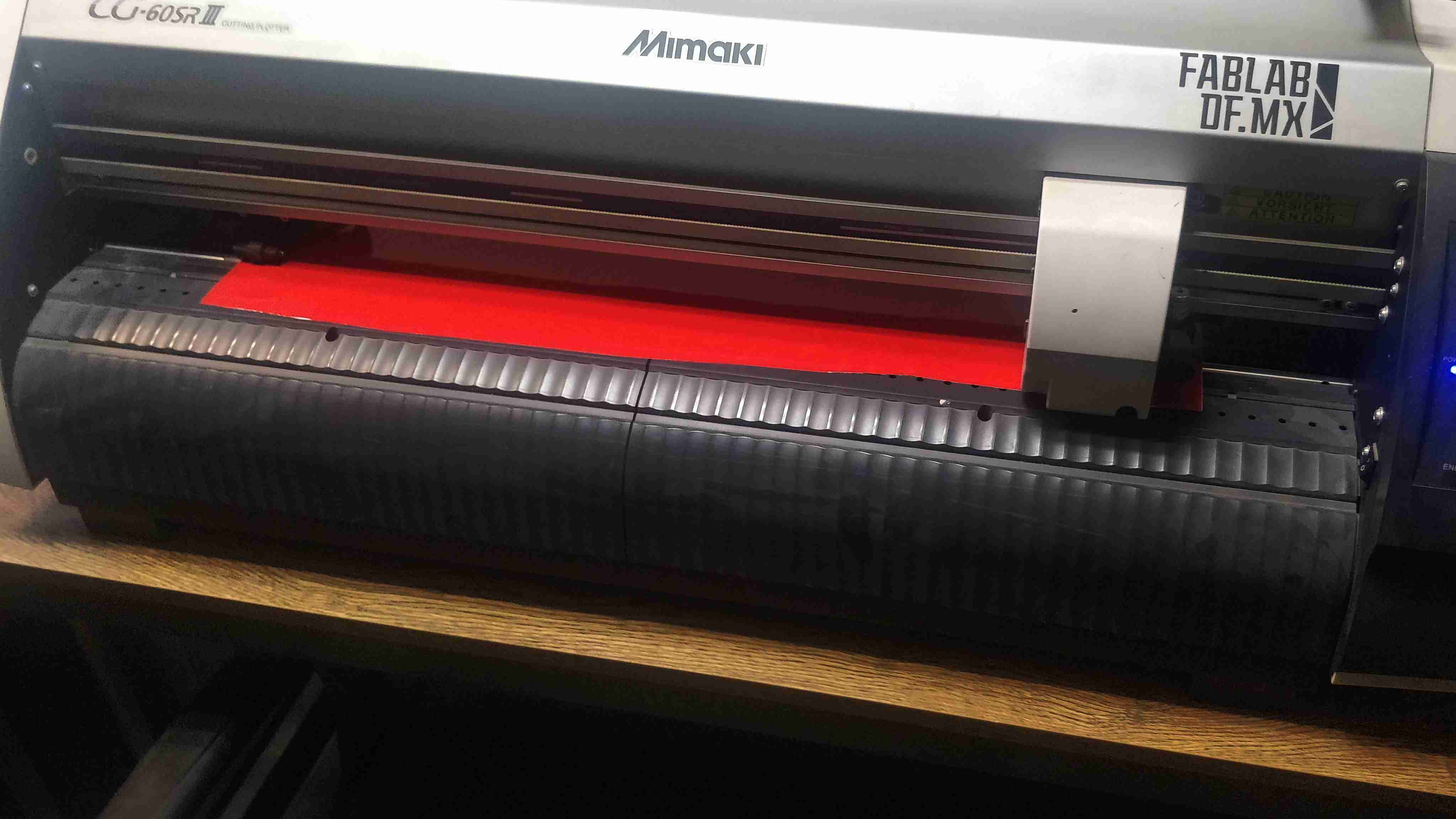
Vinyl Cutter
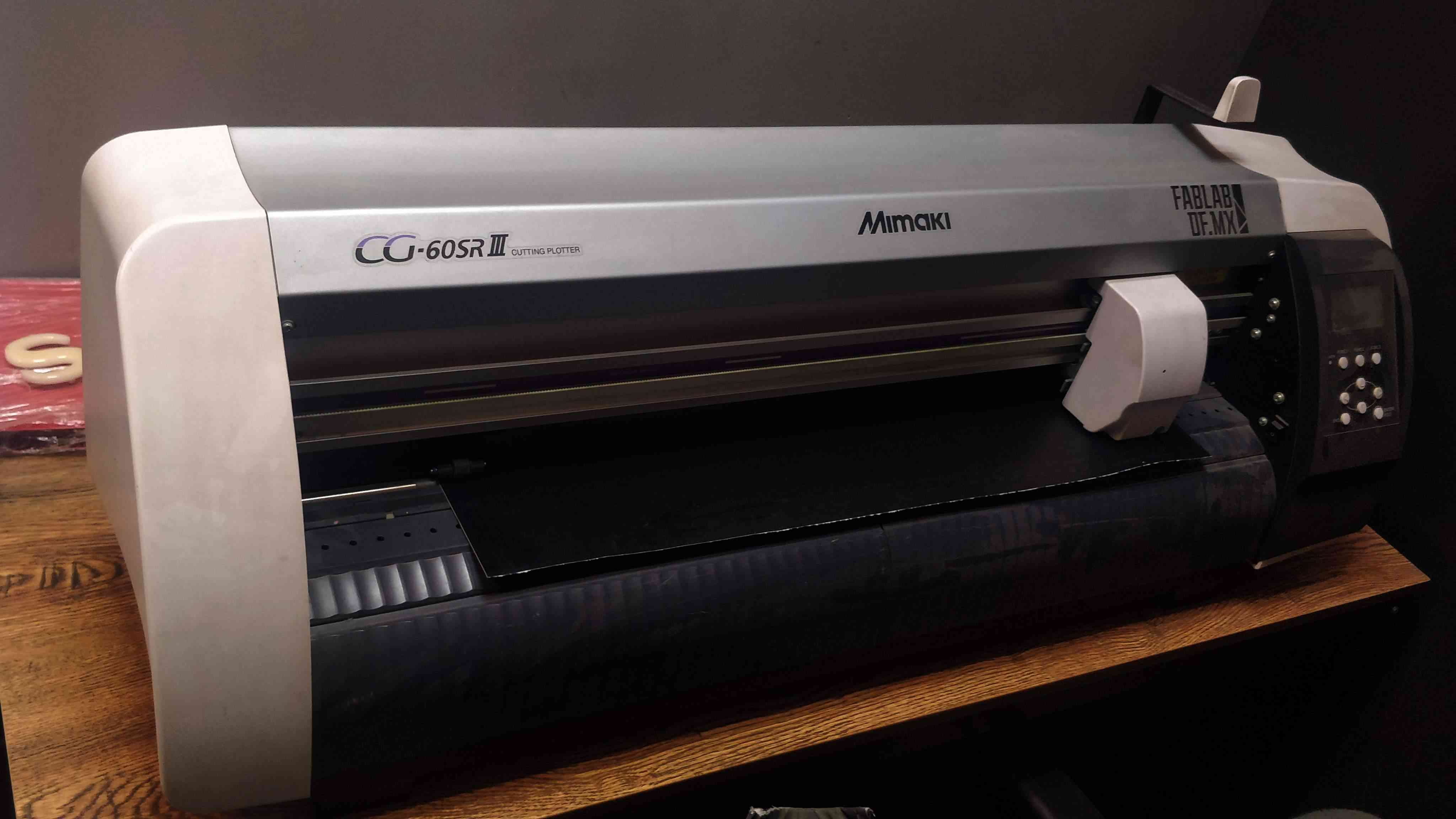
The vinyl machine where I developed my practices is the CG-60SRIII from Mimaki. A vinyl cutter works like a plotter, except that it moves a knife instead of the pen. Depending on the vinyl thickness the blade must be adjusted to go deeper.
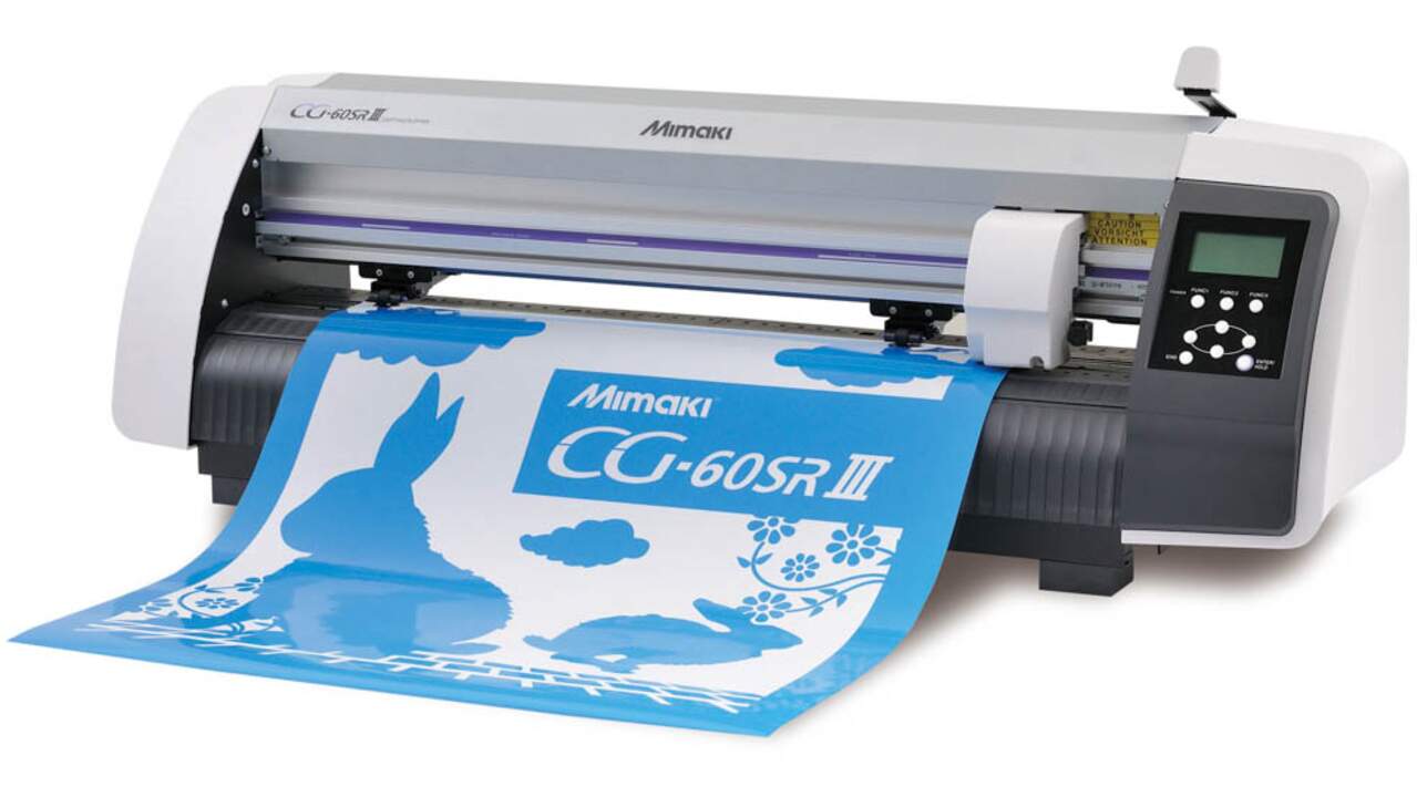
The following table shows the main specifications of the machine:
| Characteristic | Value |
|---|---|
| Model | CG-60SRIII |
| Working area | 606 mm x 51 m |
| Maximum cutting speed | 70 cm/s |
| Acceptable sheet width | 90 to 740 mm |
| Software | fine Cut 9 and Simple Cut |
The manufacturer recommends using 30 cm/s as a standard speed while the pressure can vary from 30 g to 120 g depending on the material thickness. The other parameter that must be adjusted is the offset which depends on the blade that we are going to use. In this case, I used the standard blade for cutting adhesive-backed sheet like vinyl. It is hardly broken but higher cutting pressure is required, a drawing of the blade is shown below:
Thus, I started with a manual adjustment of the blade height where I follow this video. After the blade was adjusted, I set the speed to 30 cm/s and the offset to 0.3 like the previous drawing of the blade shows. Later, I did multiple square tests that can be sent directly from the plotter where I found out that the best pressure for the vinyl that I was using it was 60 g.
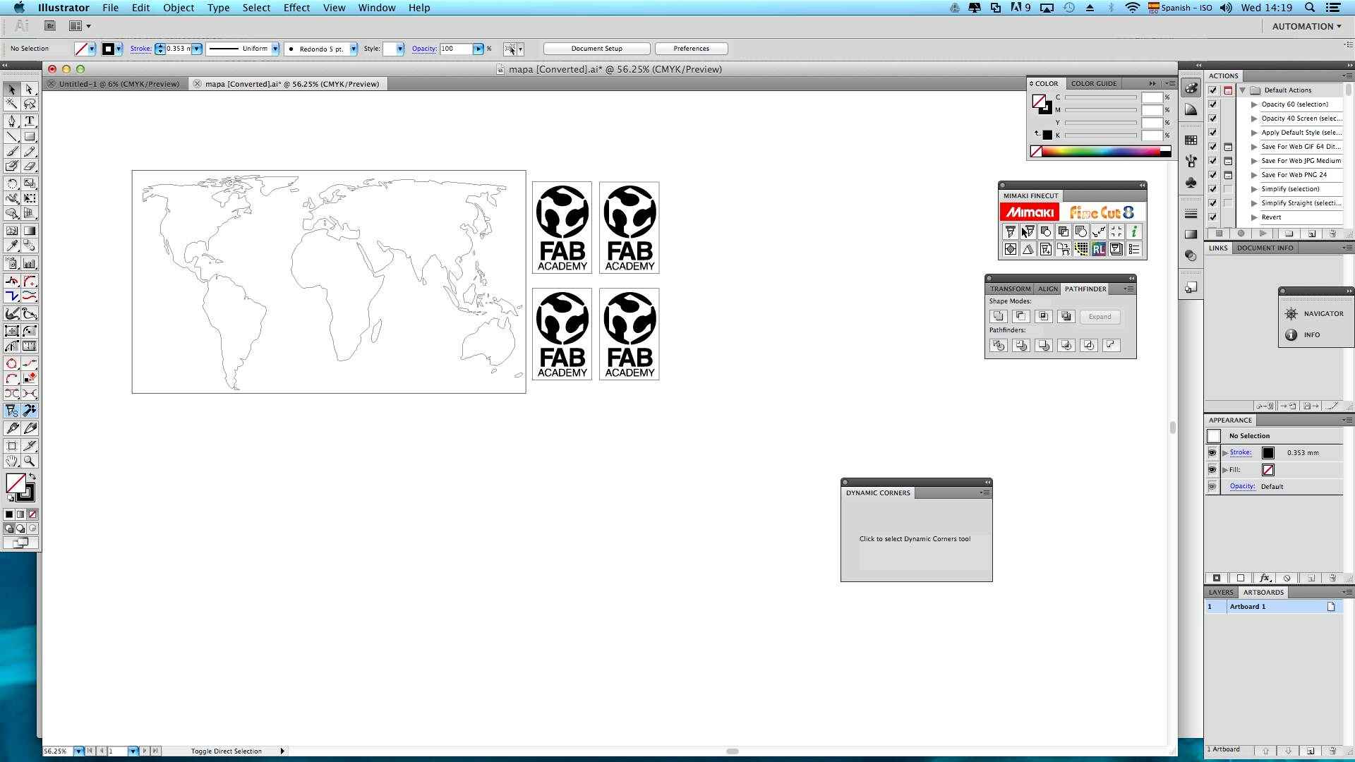
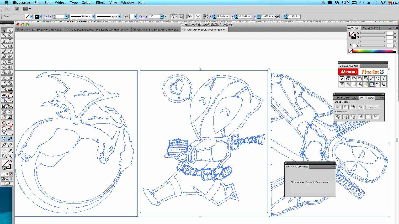
Once I finished the setup, I used the same vector of the world map and I also traced the FabAcademy logo in Inkscape. Nevertheless, I had to import the vector to Illustrator because a plugin can be installed in this software in order to send the job as a printer. The first problem that I faced when importing the files to Illustrator was related to the vector and the page setup in Inkscape. Illustrator showed me a message about a problem converting the vector and use them in Illustrator but later I realized that the problem was solved when I put my vector inside the page that I declared in Inkscape. Therefore, if the vectors are not inside the page, Illustrator will not recognize them.
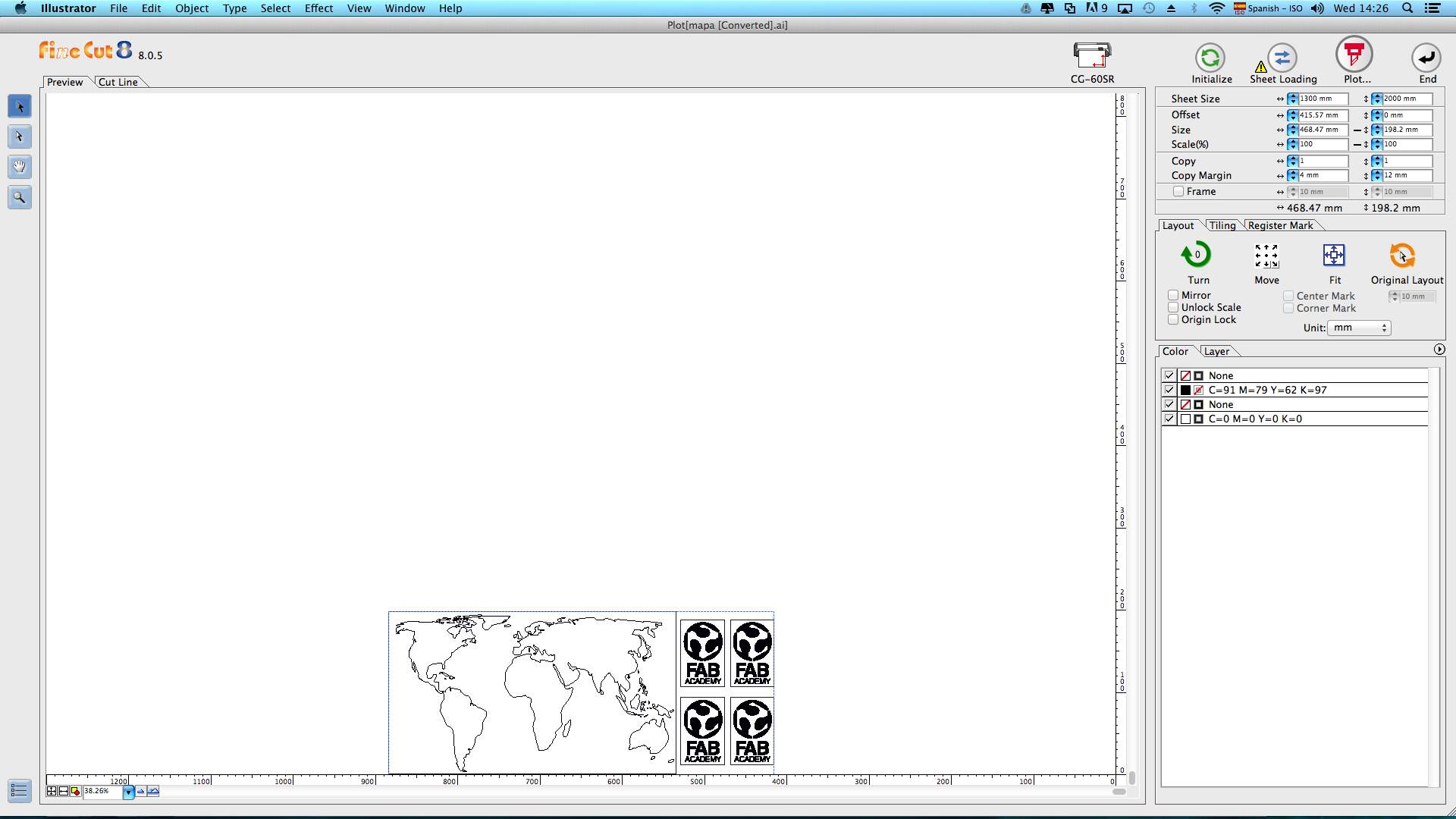
Illustrator needs the driver and Fine Cut 9, so I followed a Mimaki tutorial that shows step by step the installation process and the how to send files to the plotter. After the installation was completed, I had to go to the Window menu and select "Show FineCut Menu" to be able to send the required files. To send the file, I clicked the first icon on the top-left to plot the selected vectors. This action will display a new window that shows the selected vector as well as the position and dimension settings on the right side. On the top-right corner, I had to change the width to 580 mm which is the width of the vinyl and I also positioned the vectors in the bottom-center of the vinyl with the Move function in the Layout Menu.
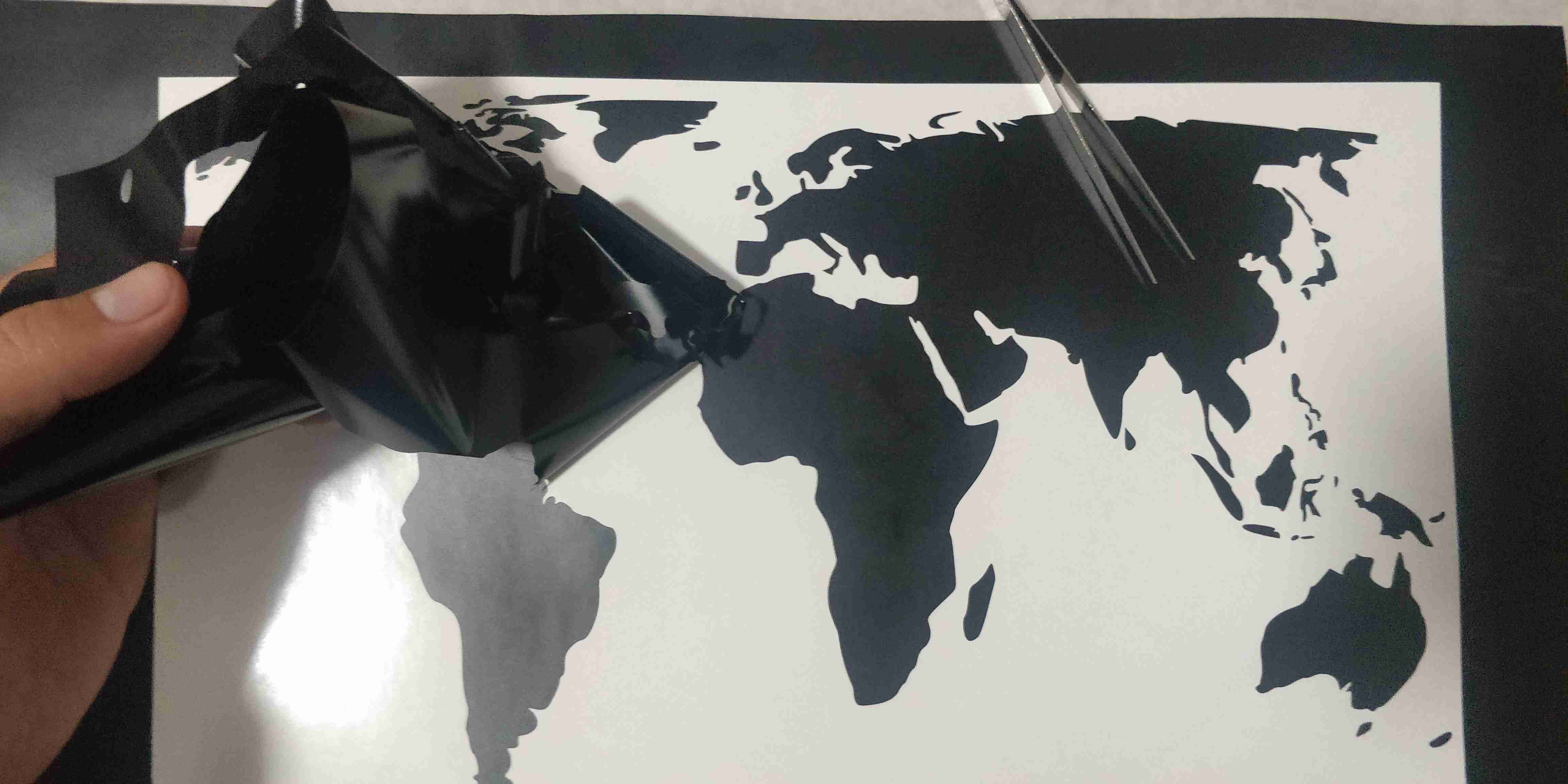
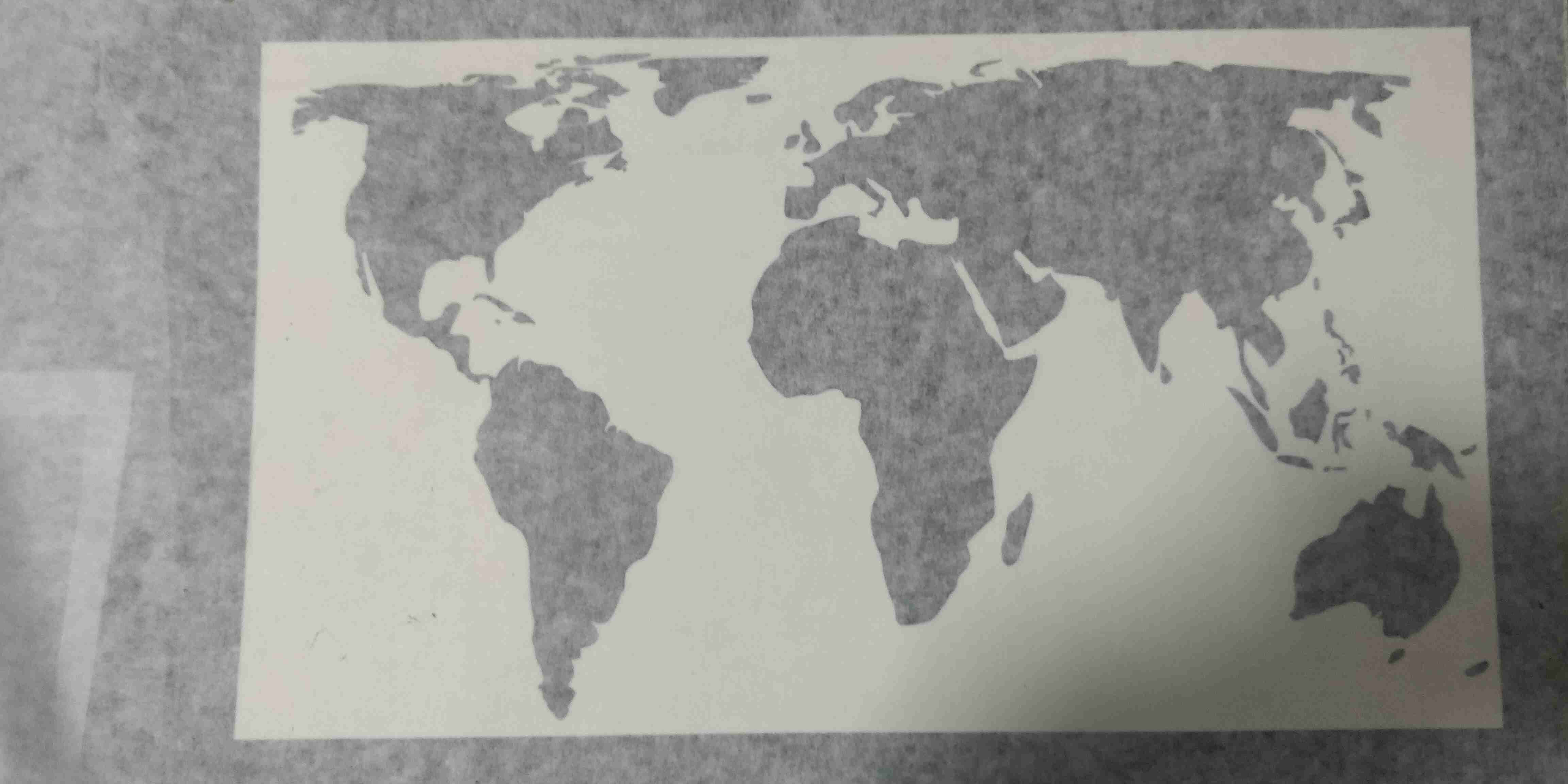
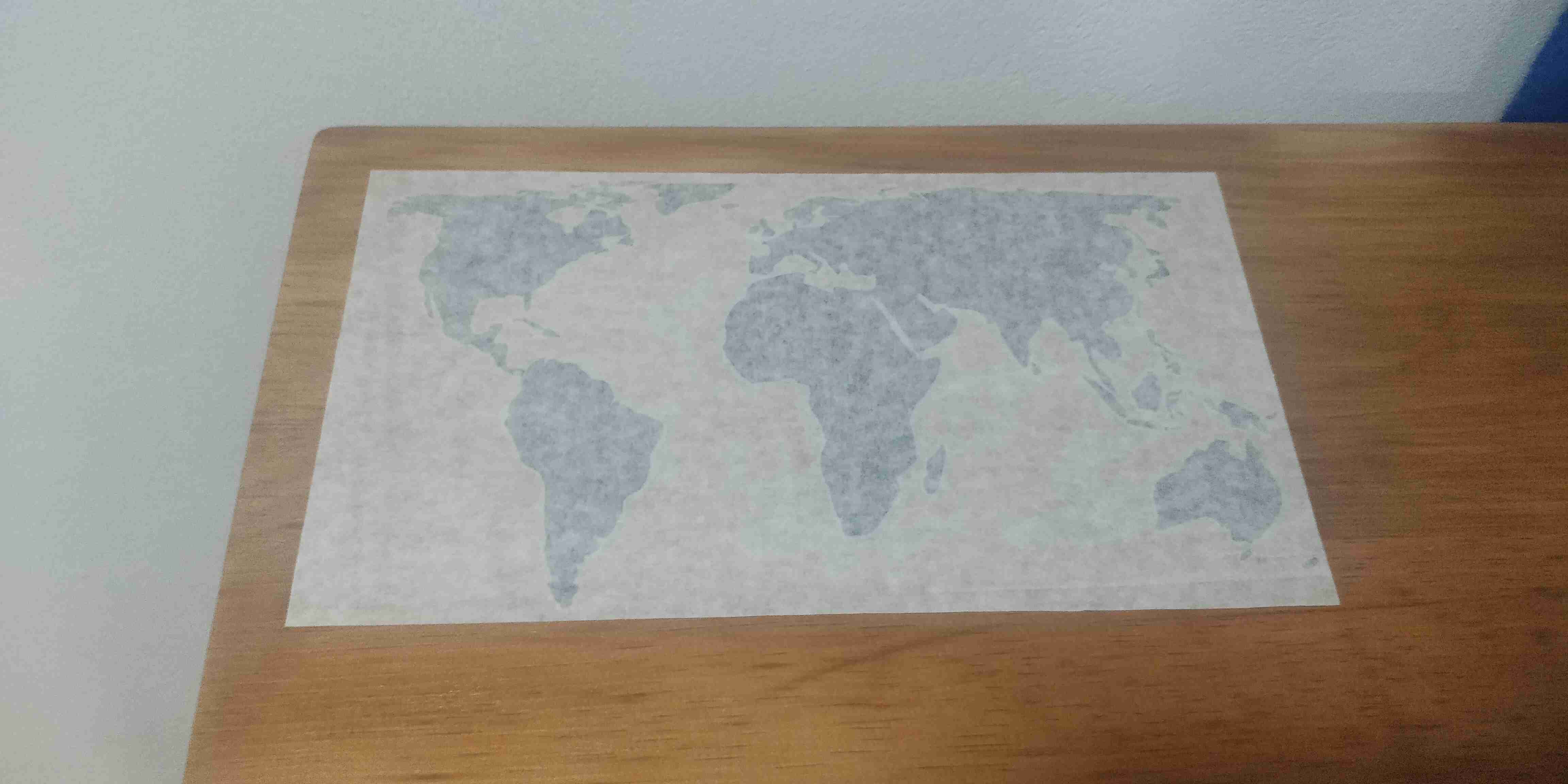
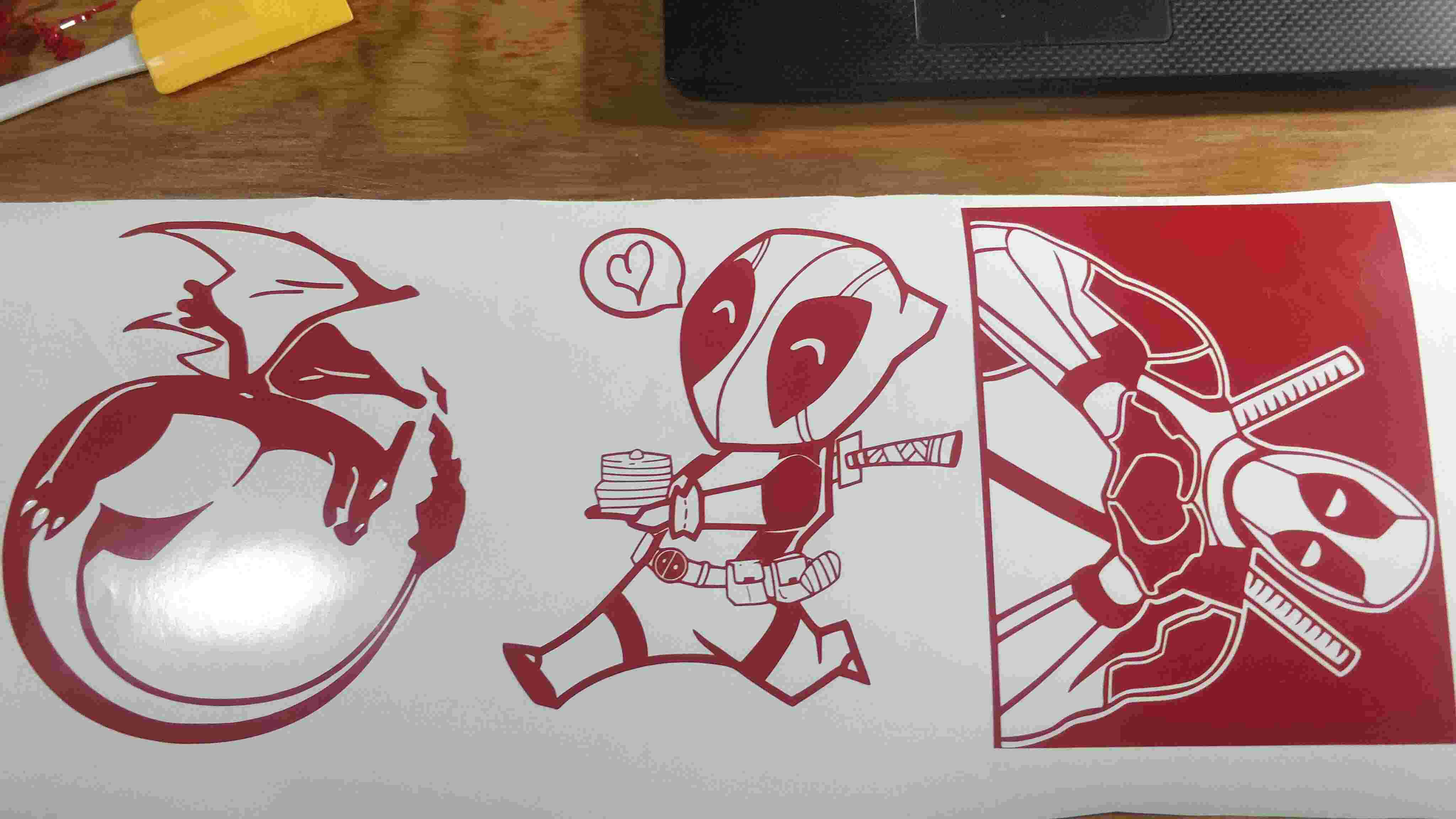
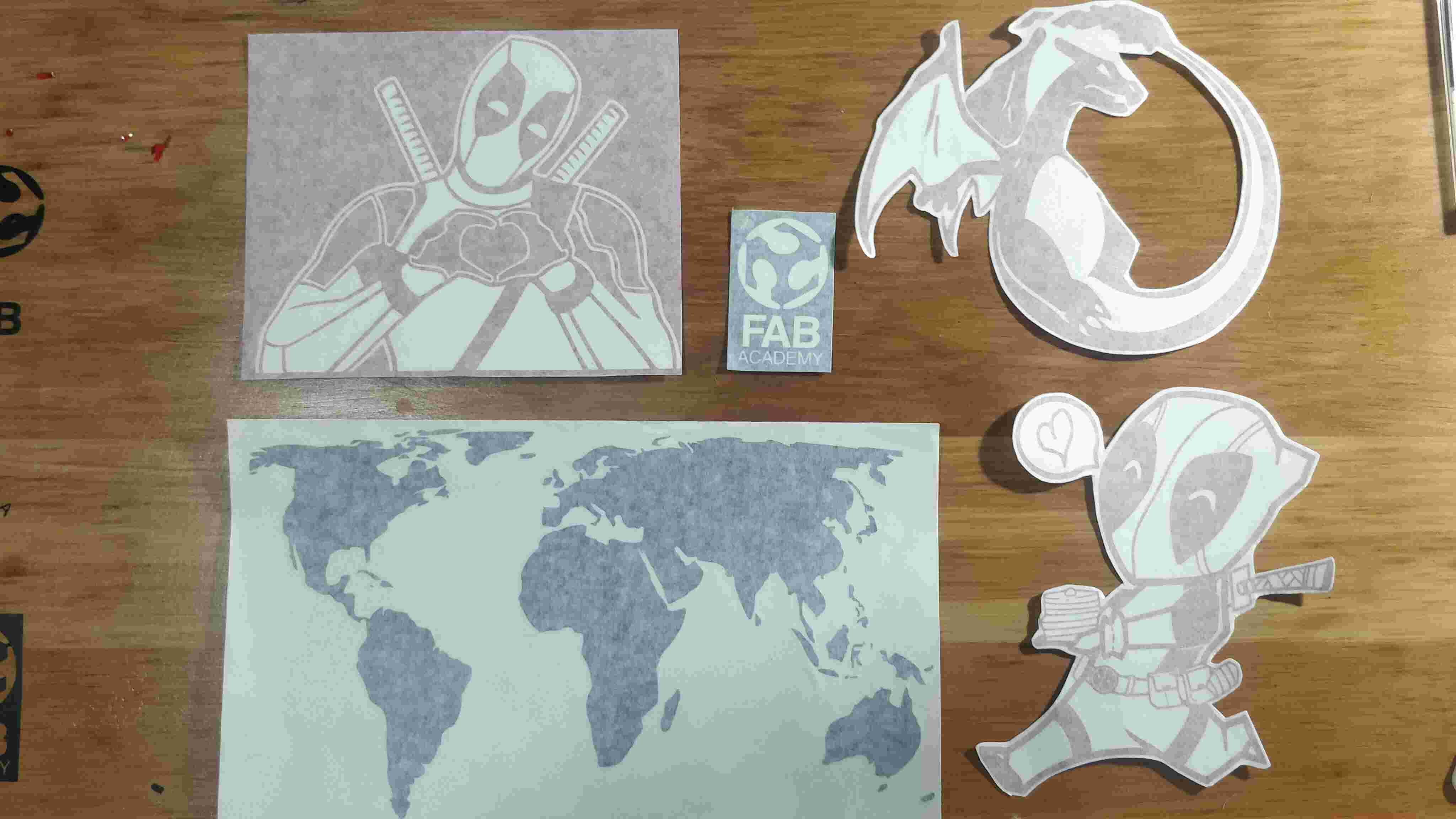
After the plotter finished the cuts that I sent, I proceed to cut the piece of vinyl where my design was with a cutter. Now it is time to weed the excess of vinyl and it is also time to place the transfer paper over the design as the following pictures show. With the transfer paper over the design, we can trim the design to have only the cut vinyl.
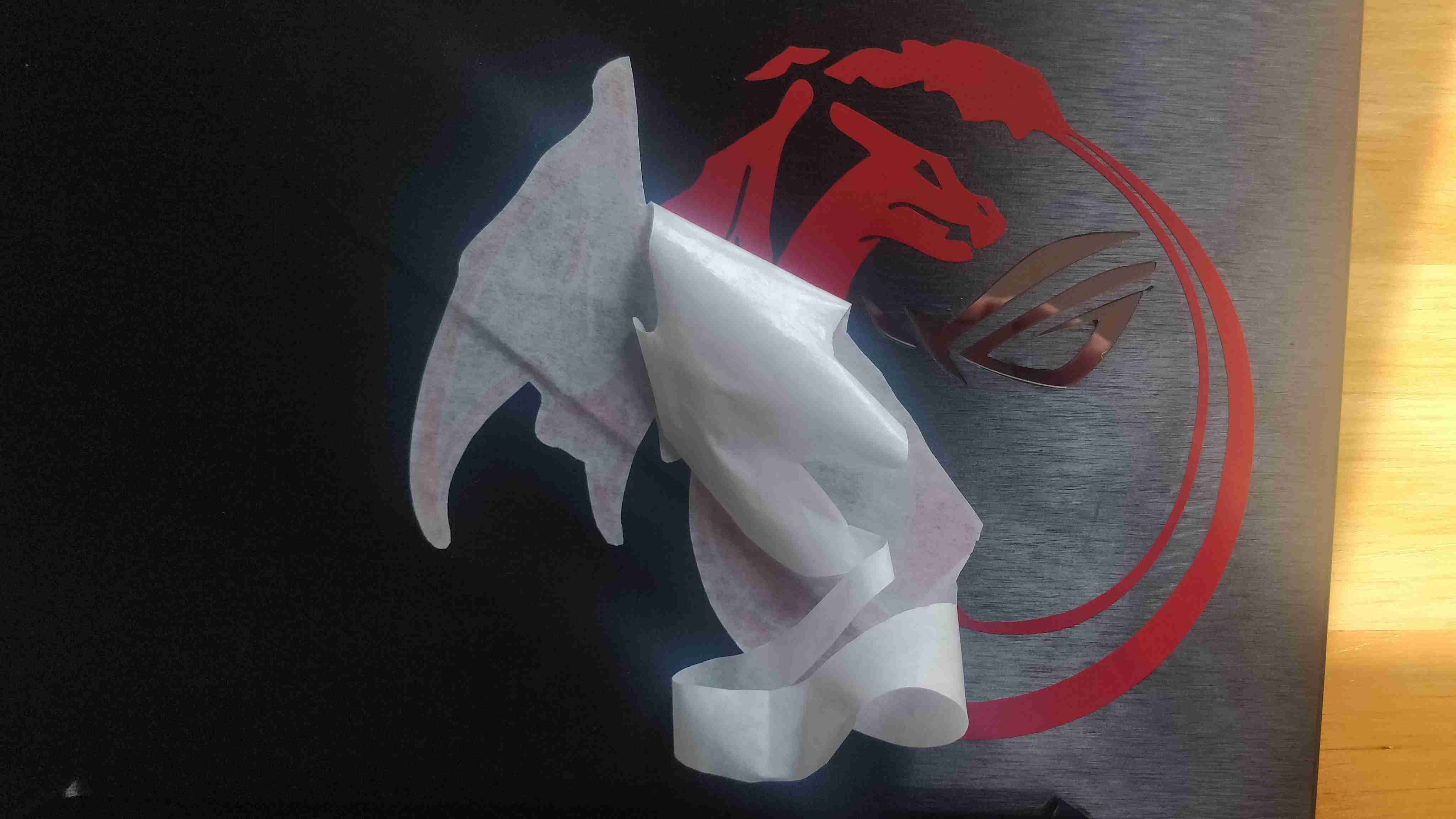
In order to apply the vinyl, we need to remove the backing of the vinyl and later apply the vinyl over the desired surface as it is shown below. Remember to press the design to remove any bubbles.
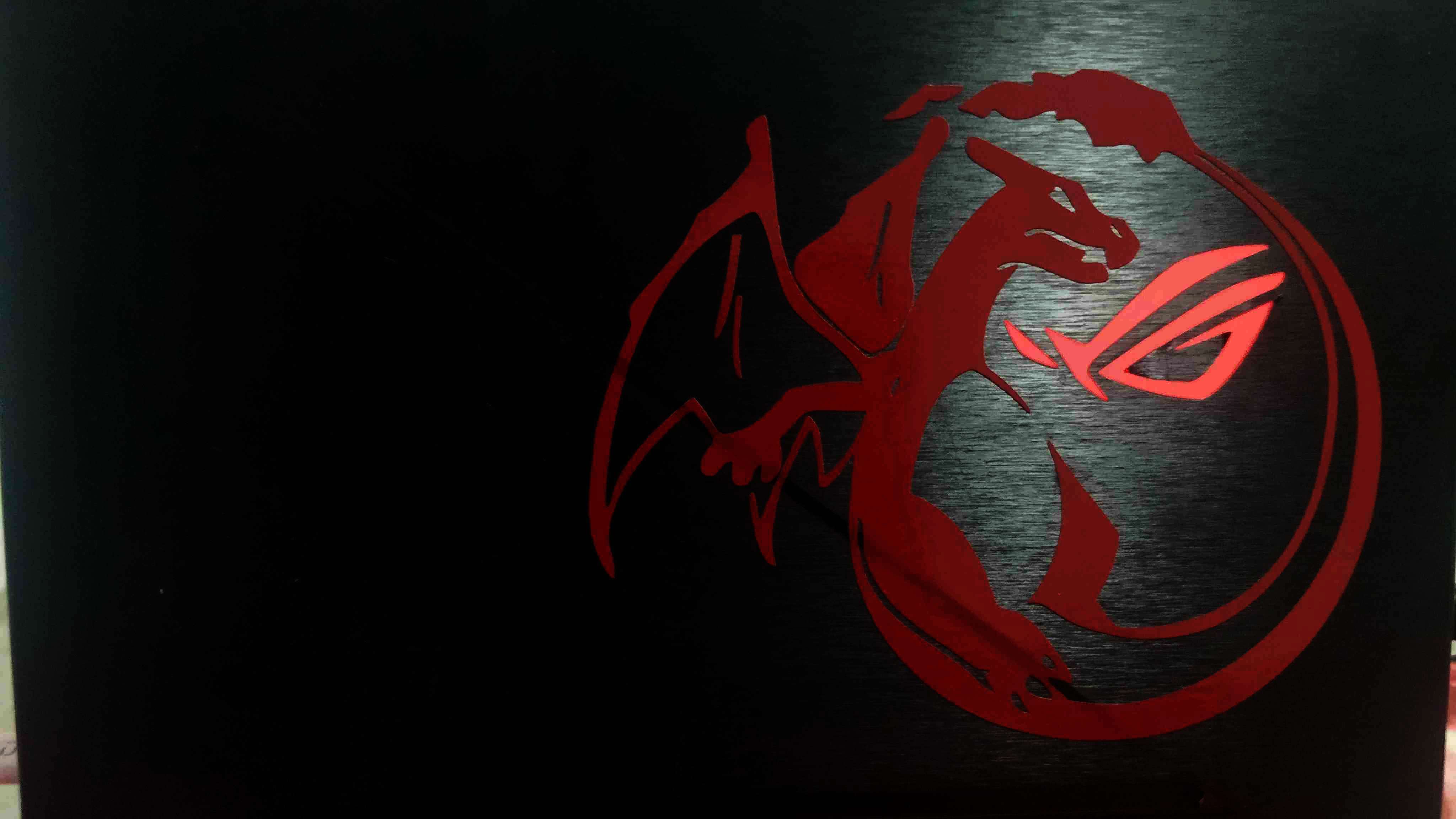
Finally, we can remove the transfer paper and admire the beautiful design that we have made.
Since I really enjoyed the vinyl process. I decided to cut other designs with a different vinyl. Nevertheless, the process is exactly the same.
- Trace the desired design using a software like Inkscape
- Export the dxf file to Illustrator
- Select the desired vector and click on the Plot button over the Fine Cut Menu
- Adjust the width of the vinyl
- Adjust the position of the vinyl to the bottom-center
- Send the file
- Realease a little bit more of the vinyl and cut it with a cutter
- Weed the excess of vinyl
- Place the transfer paper over the vinyl
- Trim the design in order to have a cleaning view of it
- Remove the backing of the vinyl
- Place the vinyl over the desired surface
- Press the vinyl to eliminate any bubbles
- Remove the transfer paper
- Enjoy your Creation !
Finally, I added a small video of one of the cutting process in the vinyl plotter.
Files created
Useful Resources