Computer-Aided Design
During the second week I kept working on my website but I also got used to multiple programs to draw, render, animate and many other useful tools to sketch an idea.
2D Design Software
I initially worked with GIMP and Inkscape to create and modify 2D drawings. The main difference between this two programs is that GIMP creates raster images while Inkscape creates vector images. But beside the name what is the real difference ? A raster image is defined by pixels and its resolution depends on the quantity of the pixels that it has. In the other hand a vector image is defined by paths and it does not have a fixed resolution which means that display resolution depends on the rendering device such as monitors. The Printing Connection created an example to show that difference between this two type of images.


GIMP

GIMP is a free cross-platform image editor which is really helpful because anyone can change its source code and distribute its changes. There are also many 3rd party plugin to increase GIMP productivity. In order to install this software, download the required executable from here and follow the given instructions.
After the program installation, I decided to practice the creation of raster images and I created a robot face with the following tools:
- Rectangle select tool to create the contour of the face
- Elipse select tool to draw the eyes and the antenna
- Paths tool to do the ears and the mouth
- Text tool to write the text over the logo
I enjoyed working with GIMP and now I have a better understading about raster images creation. The following picture shows the final
result of the robot in png format.

Inkscape

Inkscape is a free cross-platform vector graphics editor which as well as GIMP anyone can participate to improve the software. However, Inkscape allows you to create cartoons, clip art, logos, typography, diagraming and flowcharting since it uses vectors to rendering them at unlimited resolution. To install this software you can download it here and follow the installer instructions.
I have been using inkscape for the last two years and I fell really confortable using it. Actually, it is the tool that I use the most to create vector images or add objects to an image. Since I was showing the difference between a raster image and a vector images I used inkscape to convert the raster image created in GIMP and transform it to a vector image. This action can be done with the following steps:
- Copy the image in the workspace
- Go to Path menu and select "Trace Bitmap"
- Select Brightness cutoff and adjust the threshold depending on the requirements
- Check "Smooth", "Stack scans", "Remove background"
- Click "Ok" and erase the image from the workspace
To see the difference between both images, the following picture shows the result of the bitmap tracing in svg format.

3D Design Software
After practising with 2D design softwares, I proceed to work with softwares that support not only 2D design but also 3D design. The softwares that I tried out were: SolidWorks, FreeCAD, and Fusion 360. In the three softwares, I executed the same 2D design and I also draw a servomotor for the 3D design. Nevertheless, I draw a different servomotos in each software since they are the servomotos that I want to use for my final project. The main objective of these drawings is that I can comprehend the differences between them and choose the option that suits me the most.
SolidWorks

SolidWorks is a modeling computer-aided design software published by Dassault Systemes. This softwares allows the designer to solve connected designs with many systems such as mechanical, electrical, and electronics systems. However, the software is not free and the user must pay a subcription to use it. The executable to install the program in Windows can be found here. Once you have selected the version you just need to follow the instructions.
It is not my first time using SolidWorks but I wanted to do a 2D design and a 3D design. The next images show a 2D design which has three different shapes (Triangle, Square and Hexagon). I used the following procedure to create these shapes in SolidWorks:
- I created a new part in the initial menu
- I selected the plane X-Z to work. You can select it with the cube on the top-right
- I clicked left button over the plane and I selected "draw an sketch"
- I used the line command to draw the shapes
- When I selected two lines or points, a menu on the left allowed me to chose a constraint
- After I chose the required constraints, I used the dimension command to put the height
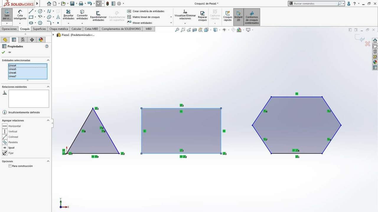
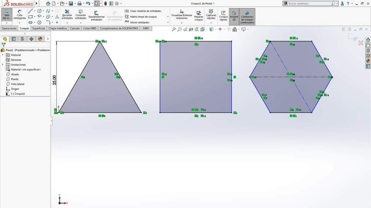
The image on the left shows the initial drawing where there are no constaints or dimensions. The right image displays the final result of the design because it is fully constrained. It is important to note that I had to add two construction lines to force the required hexagon shape.
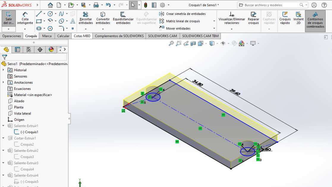
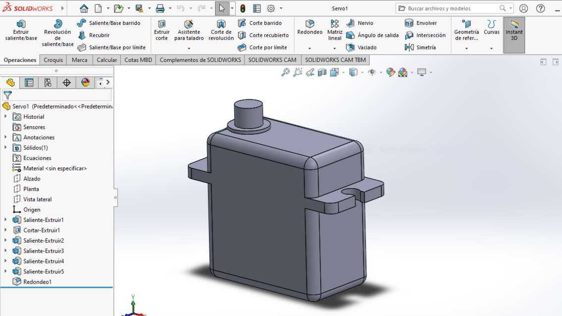
For the 3D practice, I drew a servomotor that I had in my house but I do not know the model. The main sketch of the servomotor was done with the same steps as the previous shapes. The mainly difference is that I created multiple sketches to extrude and substract the paths on the sketches. The image on the left show the main sketch to build the servomotor and the image on the right shows the final servomotor.
FreeCAD

FreeCAD is an open-source parametric 3D computer-aided design software and its main function is to design real-life objects. This software benefits from the big experience of the open-source world which makes it powerful because there are features that can be added with plugins. FreeCAD is not designed by a company for a specific purpose instead it is produced to design from small electronic components to big scale pieces for buildings. This software can be installed in Windows, Linux or Mac and you can download it from here.
Since, I have experienced with other CAD programs, it was not diffucult for me to learn the basics of 2D and 3D modelling in FreeCAD. Nevertheless, I watched some videos that are in the FabAcademy website and that explained how to build sketches, set constraints, simulate actions, render the parts and many other things. My first 2D design was the same as the one in SolidWorks but I did the following procedure:
- In the start menu, I selected "Part Design"
- On the left menu, I chose "Create a Part" and "Create a sketch" followed of the X-Z plane
- I used the polyline command to draw the shapes
- With the sketcher constraint menu, I set the same constraint that in SolidWorks
- Finally, I use a vertical dimension to set the heigh of the shapes
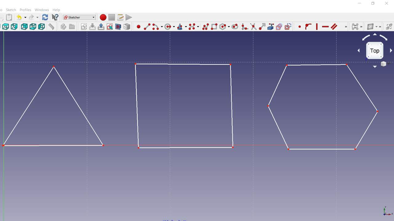
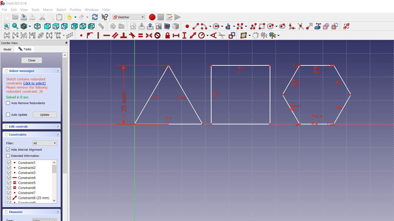
The previous images show the initial sketch and the sketch with constraints in the same order as in the SolidWorks example. The biggest problem using FreeCAD is that I had to define the constraints after I finished each shape because the program has problems when you have multiple shapes no fully constrained.
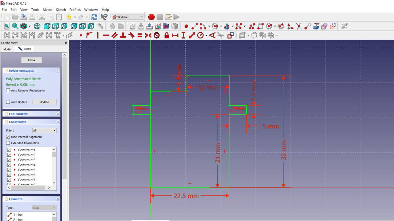
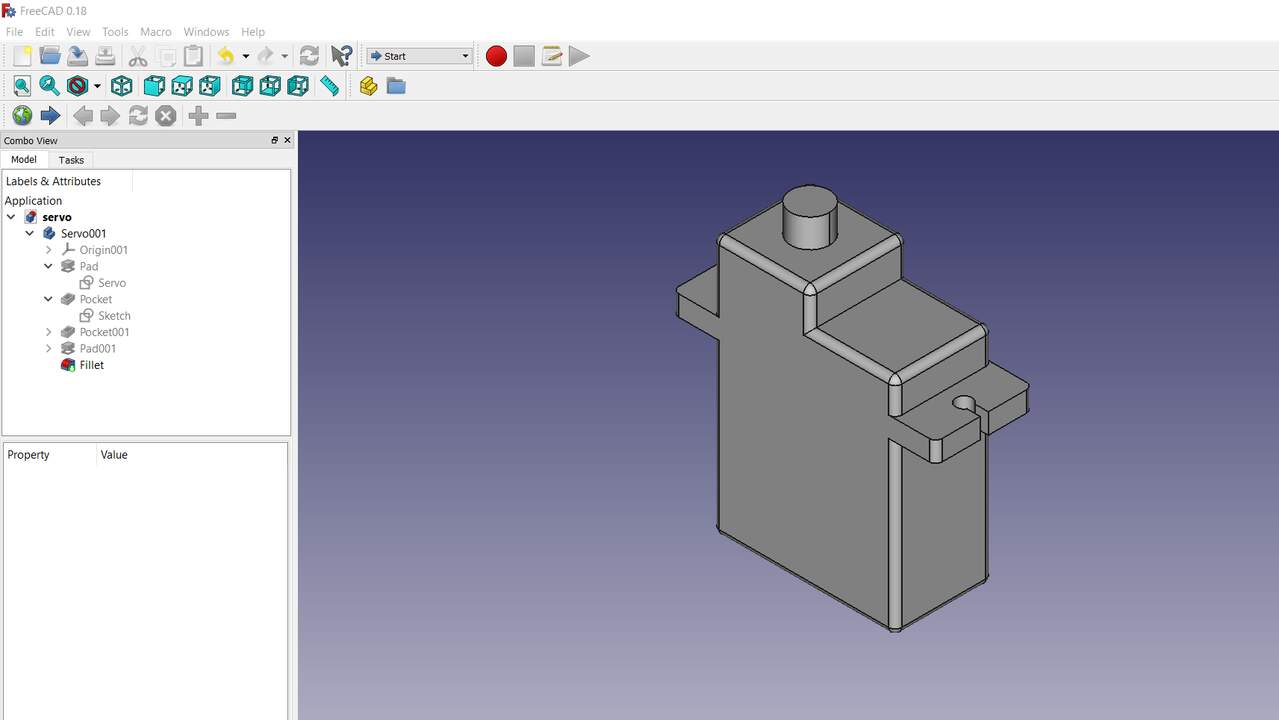
After practicing with 2D sketching in FreeCAD, I proceed to draw the Servomotor MG90S which is a metal gear servomotor and which I am interesed on use in my final project. The proces to build the servomotor in this programs was the same at the beginning with the difference that I also had to extrude and substract paths from the main body. My biggest problem was to get used to the views and the mouse functions since there are difference between FreeCAD and SolidWorks or Fusion 360. At the end, I managed to finish the 3D design of the servomotor that I wanted which is show below. The left image shows the main sketch to build the servomotor and the right image shows the MG90S servomotor.
Fusion 360

Fusion 360 is a CAD tool distributed by Autodesk and has become really popular because it allows you to sketch 3D design but you can also create a G-Code to machine the objects or create a simulation, the options are endless. Another point to its favor is that it has educational licenses and students or people in makerspaces can have them and use the educational version which is powerful enough to build whatever we are imagining. To install the educational version you just need to create an account with your student email and download the version for your operative system here
I started using Fusion 360 the last year and in my opinion is the most friendly program for CAD modelling. What I liked the most is that the files are saved in the cloud and you can access or share them through internet which is really helpful when you are working with a team. Like the two proevious programs, I started with the same 2D design although I used this procedure:
- I started selecting "New Design" in the top-left corner (Make sure you are in the design workspace)
- On the menu "Solid", I chose "Create Sketch" and I selcted the the X-Z plane
- I used the line command to draw the shapes
- I set the constraints in the same way as in SolidWorks. The only difference is that the constraint menu is on the top for Fusion 360
- Finally, I set the height of the triangle and all the shapes are fully constrained
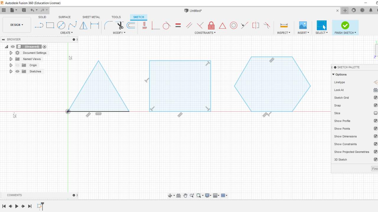
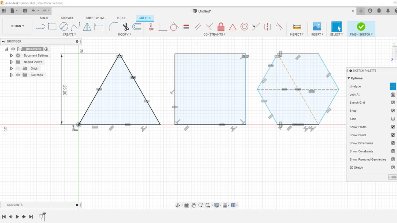
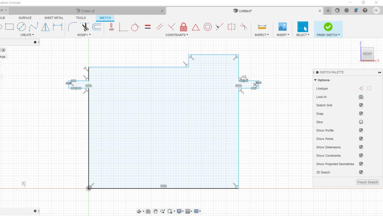
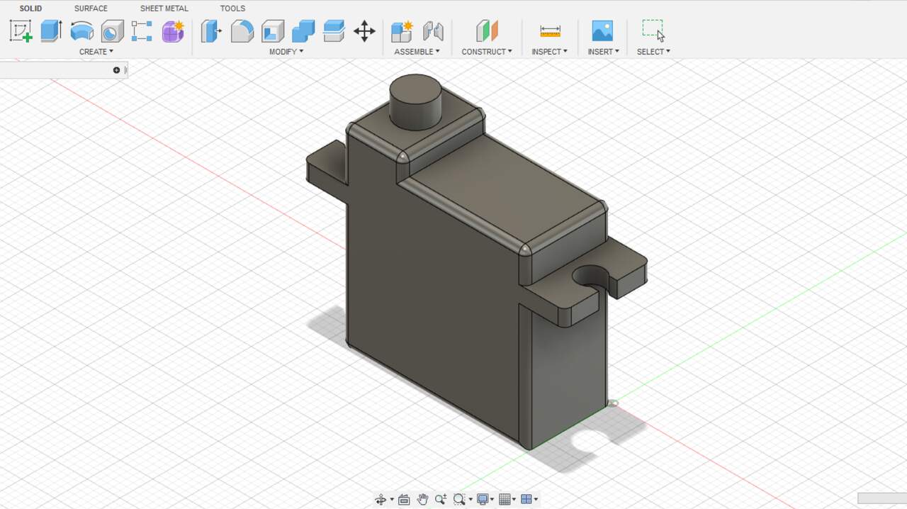
The previous images are arranged in the same way as the previous examples. Once I finished with the 2D sketches in Fusion 360, I drew the servomotor HD1160A which is the most suitable servomotor for my project so far. As well as the previous 3D modellings of the servomotors, in Fusion is also neccesary to start with the main sketch and later extrude or substract depending on the required operation. On the next left image can be seen the initial sketch to build the servomotor and in the right image the final version of the servomotor HD1160A.
My project
Designing the first version of my robot
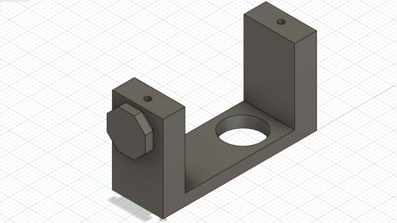
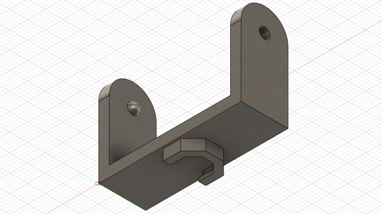
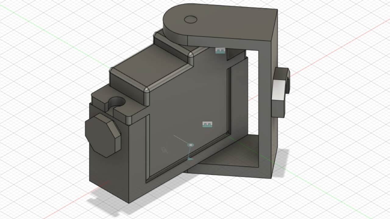
I started the design of my project when practicing but I just drew a few components of a final product. Thus, I used Fusion 360 as my main CAD software and I designed componenet by component. The first robot that I design was a spider with 6 legs and each legs has two servomotors. Since I already had the servomotors, I began with the servomotor holder and the c-profile that moves according to the servomotor movement. These two designs are presented below.
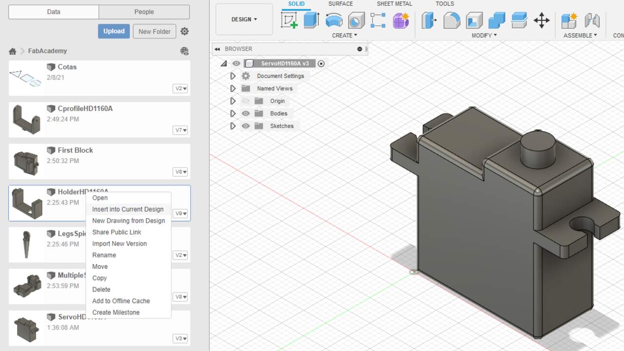
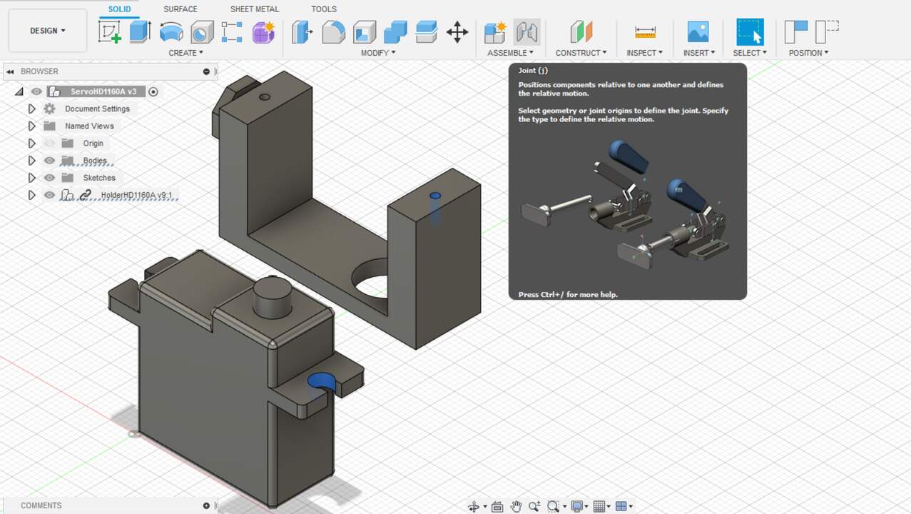
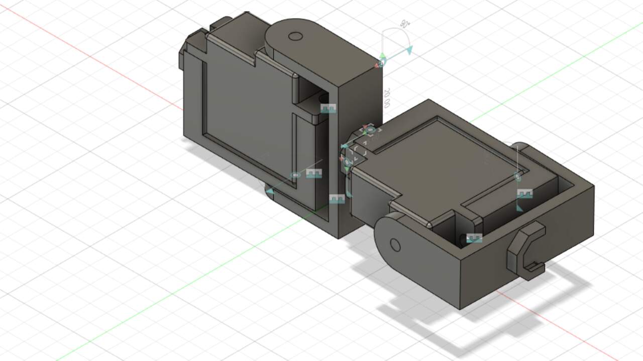
Once I finished with the two main components, I started the assembling process of the spider. I first put togheter the servomotor, the holder of the servomotor and the c-profile. To do this assembly I opened the servomotor file and I click on the top-left icon that looks like a square to see all the files that I had on the cloud. Afterwards, I searched the file that I wanted and I did a left-click over this file. A menu pop-up, and I chose the option "Insert into Current Design" and the design was brought into the servomotor file. Succeding the addition of the other part, I selected two surfaces that I wanted to joint in order to build constraints between components.
I kept adding the c-profile component and the required joint to simulate the servomotor movement and so I could get the first unit which is composed of one servomotor, one holder and one c-profile. Next, I added two units that use the servomotor holder of one unit and the c-profile of the other unit.
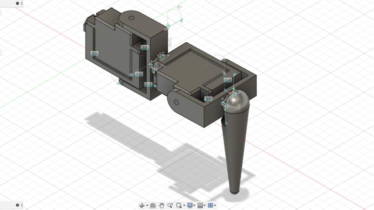
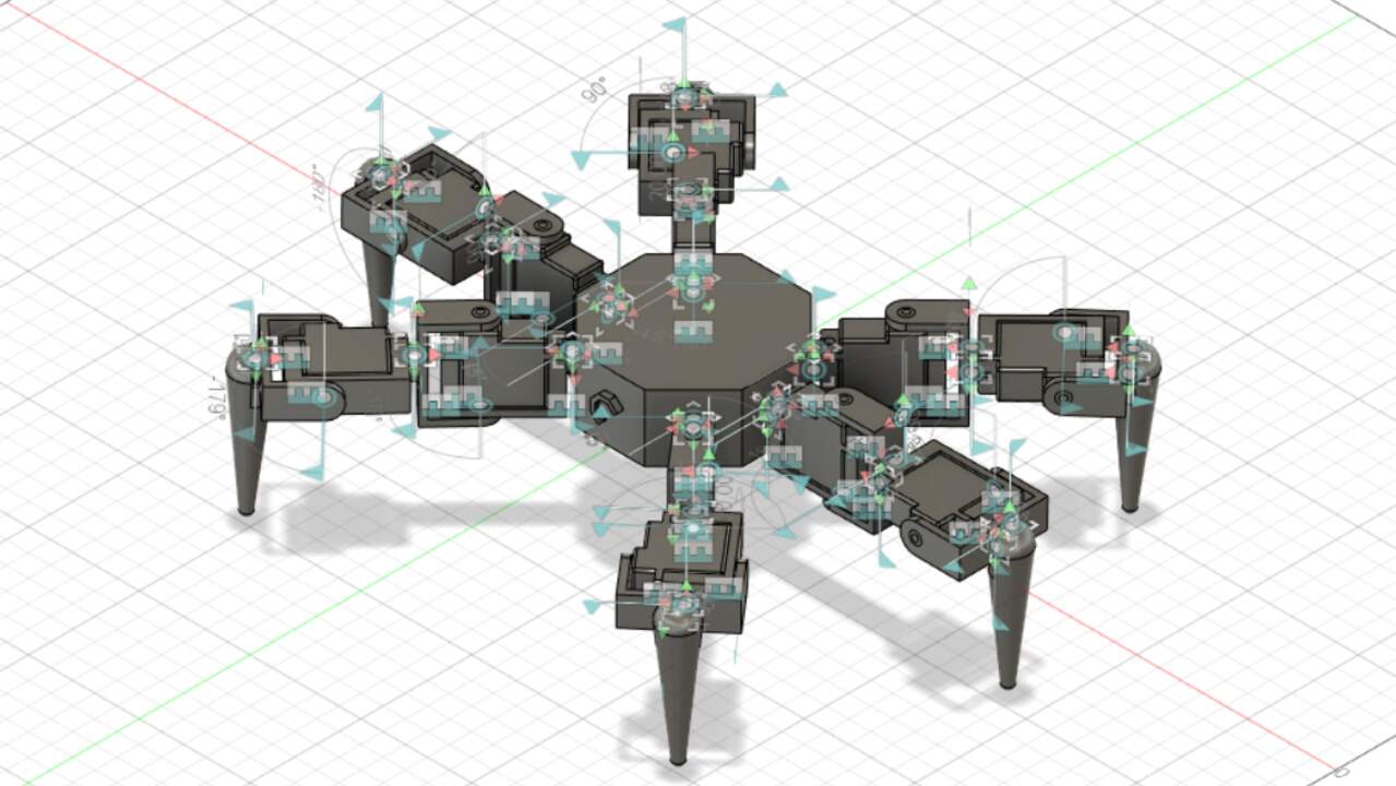
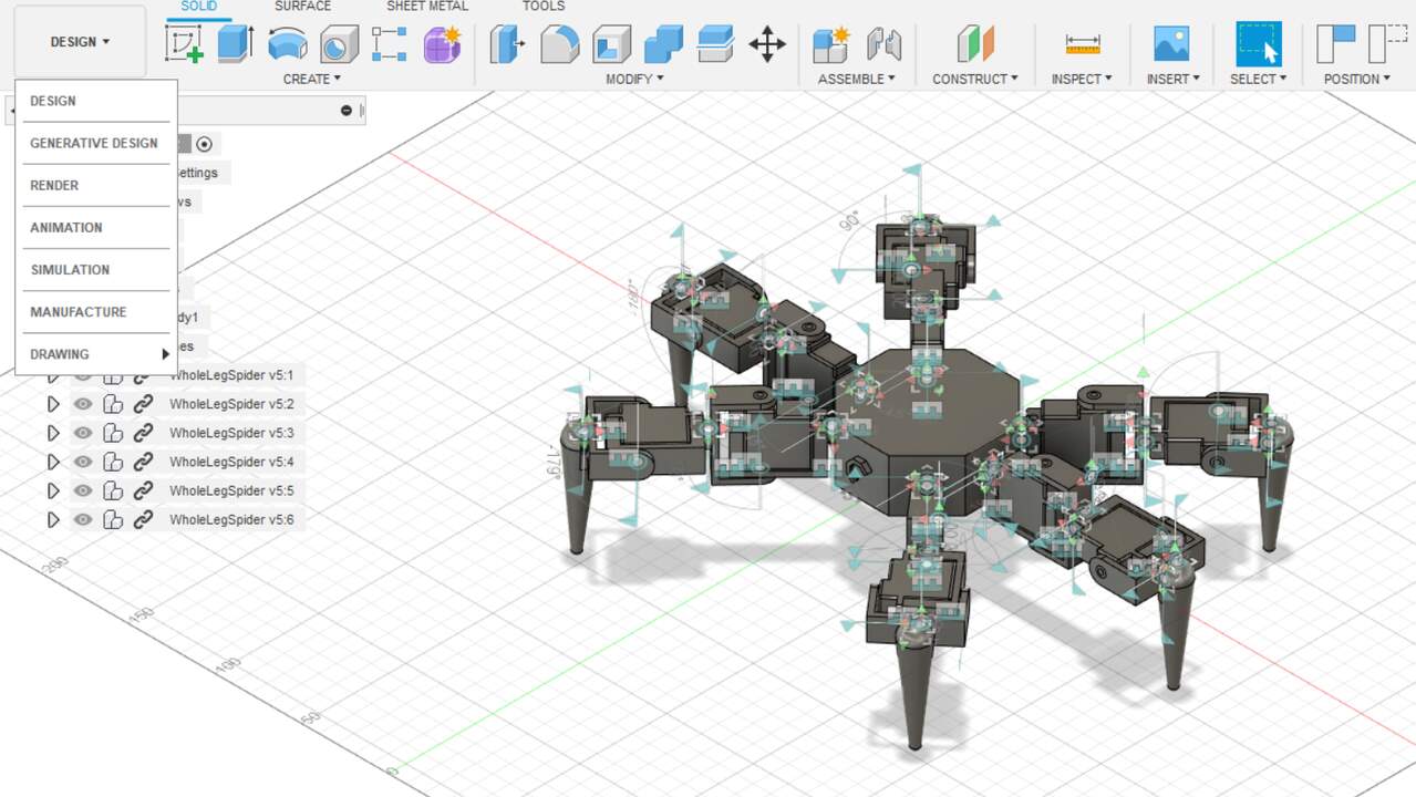
I used the design with two units and I added a leg to simulate the whole spider foot. Finally, I created a new component that holds all the feet of a spider and put togheter six feet to simulate a spider-like robot.
Rendering the robot
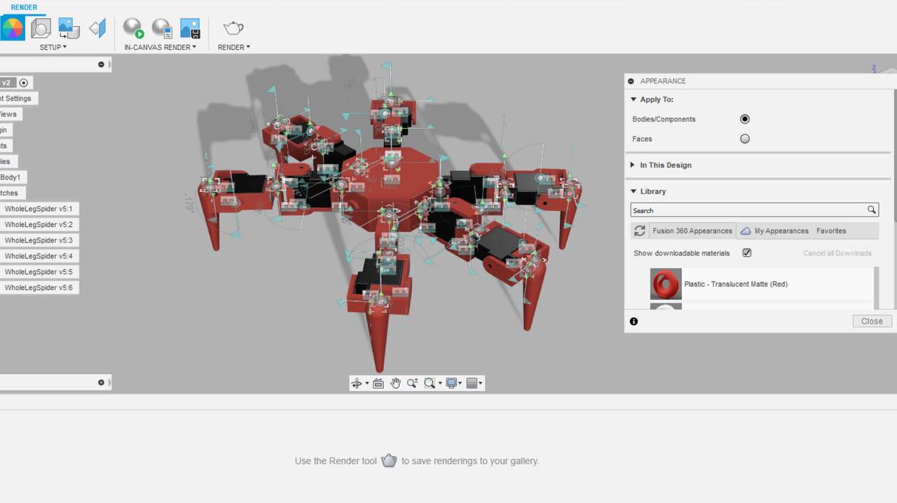
I also used the first version of the robot to produce a render. To start a render, I had to move to the render tab wich is on the top-left corner and can be seen in the images below. After selecting this option, I gave an appearance to each components. I used a black inside plastics for the servomotos and a red also in plastics for the rest of the components. The appearance can be applied from the top menu over the circle with multiple colors. A new tab will be opened and there, you can select the color that you like. To apply the color to a specific component, you must drag the wanted color over the component.
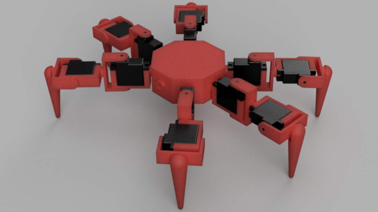
To produce a final render, you just have to click on the sphere with a play symbol and the options about the quality and dimensions will appear. In my case, I used the default setting because I have a educational license but it produce a really good result as can be seen in the image below.
Animation of the robot
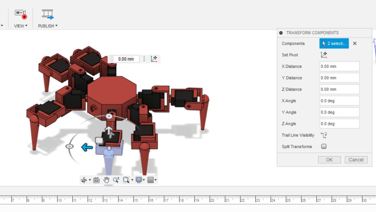
The last function that I used in Fusion 360 with the robot was the animation. The animation is really easy if you understood the joints (constraints) definition in Fusion 360. First, you must move into the animation part in the top-left menu. After you are inside the animation menu, you have to select the individual components that you want to move and choose the transform button which has a cross. If the seleccion was successful, the software will ask you about a pivot point which is the revolute or linear axis where the component will move. You can use the menu in the right to specify the required movement or you can also use the arrows over the components to move them manually. Once you like the movement, click "OK" and keep setting the next movement you want to register.
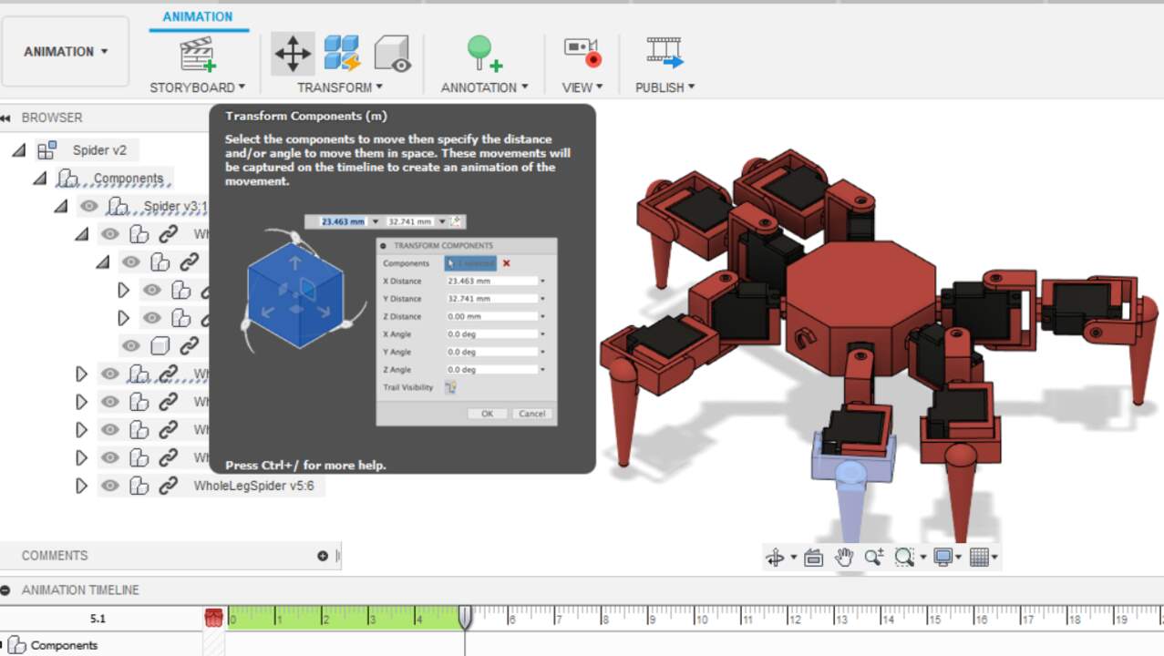
To record a video in Fusion 360, you have to click over the "Publish" button on the top menu and it will ask you the settings for the video. As well as the render, I used the default settings to create the video. Finally, a small video of the robot motion is shown below.
Files created
- Robot in GIMP
- Robot from GIMP in png
- Robot in Inkscape
- Constraints in SolidWorks
- Constraints from SolidWorks in dxf
- Constraints in FreeCAD
- Constraints from FreeCAD in dxf
- Constraints in Fusion 360
- Constraints from Fusion 360 in dxf
- Servo in SolidWorks
- Servo from SolidWorks
- Servo MG90S in FreeCAD
- Servo from FreeCAD
- Servo HD1160A in Fusion 360
- Servo from Fusion 360
Useful Resources