Week3
Computer controlled cutting
Go to:Group assignment Parametric design individual assignmentVinyl cutter
Group assignment
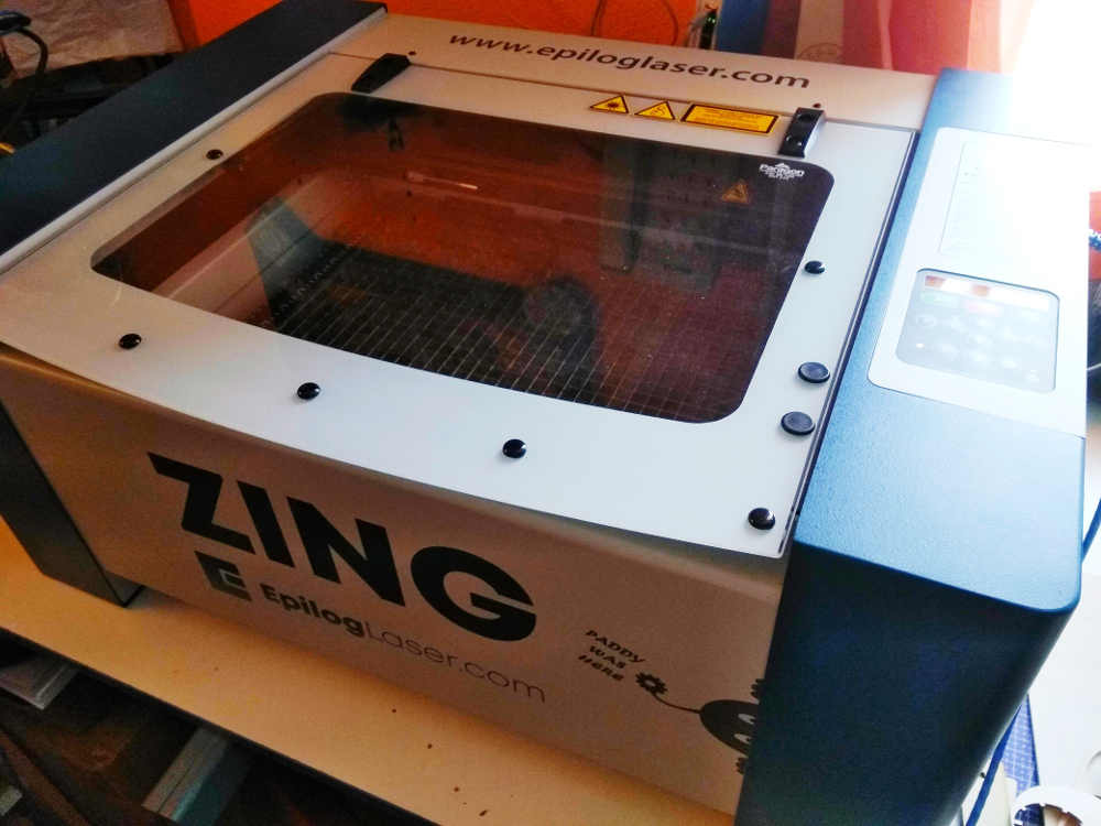
Following on to the laser set up, I have done the first burns with the zing…
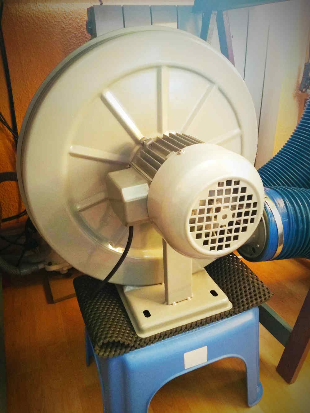
For this week's assignment with the laser machine, since I am at home, I am temporarily using this extraction system (hence the adapter I made last week). I also always keep a fire blanket near by, just in case.
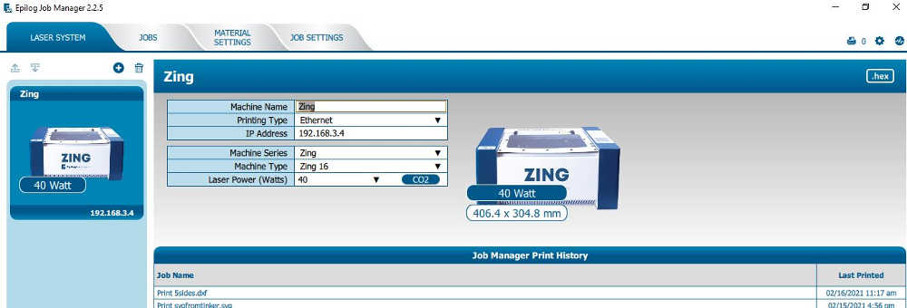
I set the laser machine up using the epilog suite, once installed, I was able to select the type of machine I am using and see all the properties:- Name and type of connection (zing - ethernet)- Model type and working area (zing 16 - 406.4 x 304.8 mm)- Laser type and power (CO2 - 40W)I will take these specs in consideration when preparing the design and parameters.
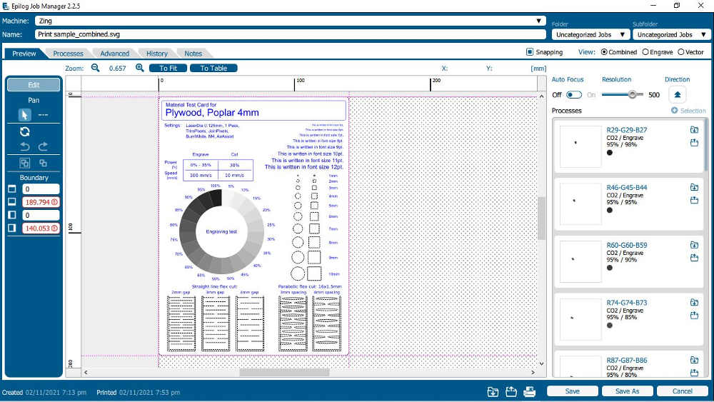
I like it! I still have to get used to the epilog suite software, I spend a bit of time trying to find things around but I eventually find out how to:- Give specific parameters to different elements.- Save parameters for a specific material or process.- Separate elements from the composition and/or merge.
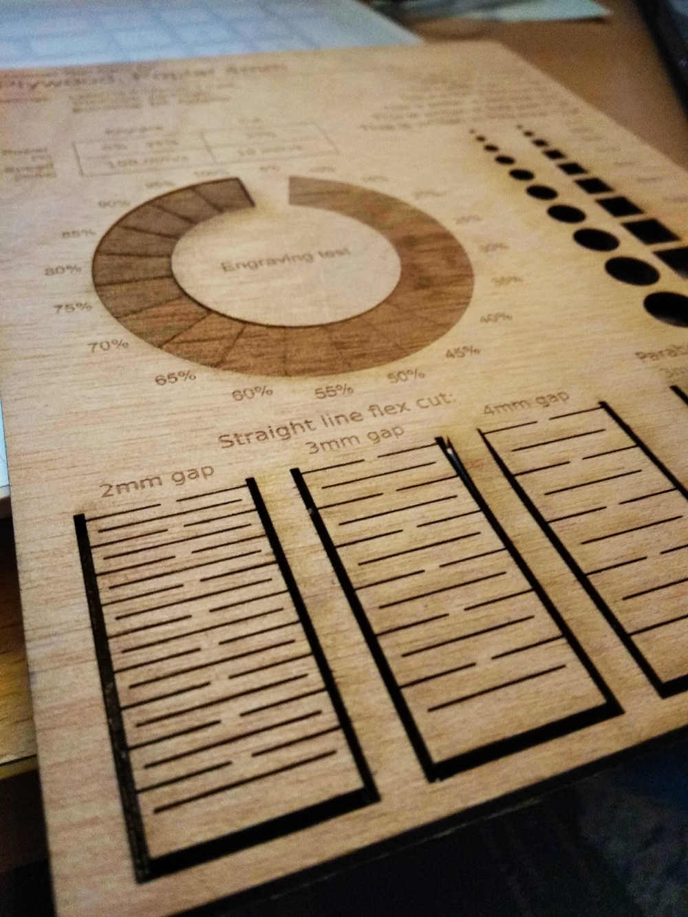
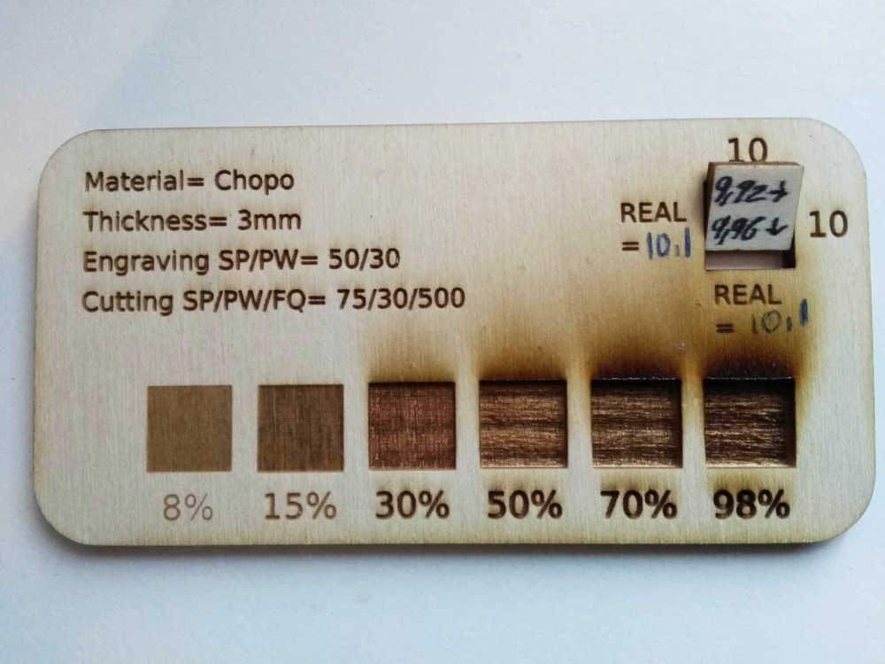
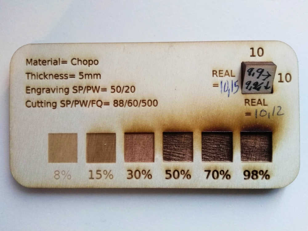
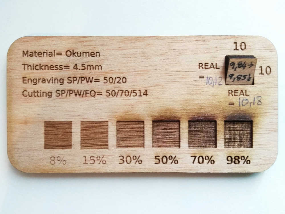
Which helped me prepare the material test card...
NOTE: I did notice that, and I don't know if it's this wood I didn't get very dark engraving and ended up with a very narrow range or color… The only difference I feel is the depth of the angraving. I must try playing with parameters more.
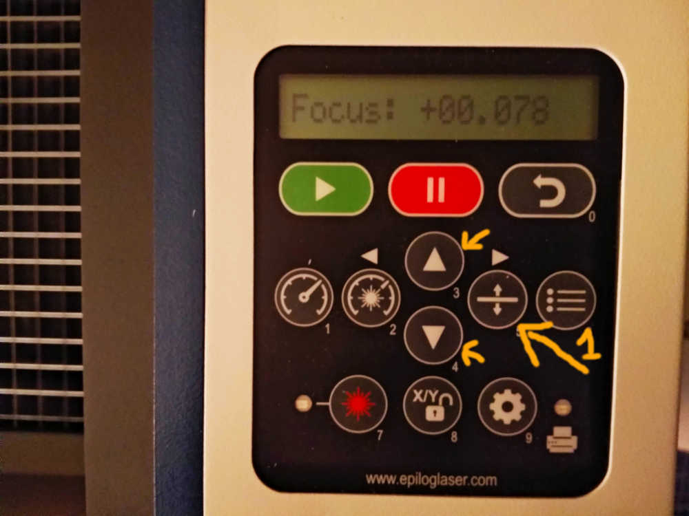
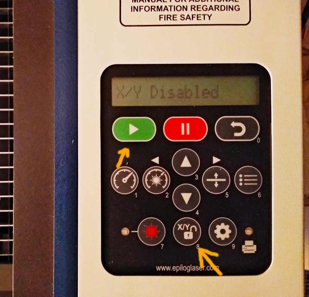
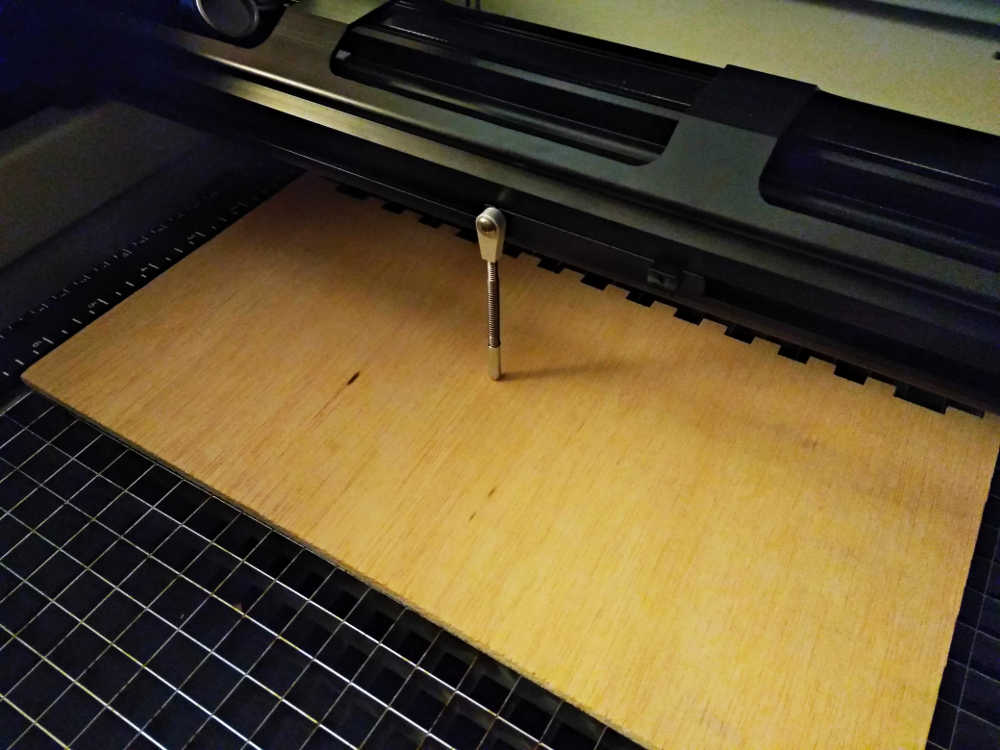
Characterize lasercutter's focus The focus on this machine is done manually, you gain control of the Z axes on the control panel ( the ”1” I marked on picture below) and adjust the height so that the pin just touches the material by the tip but stays straight. The X and Y axes can be disable to move the bridge where required. The home point is then reset by using the red pointer and pressing green.
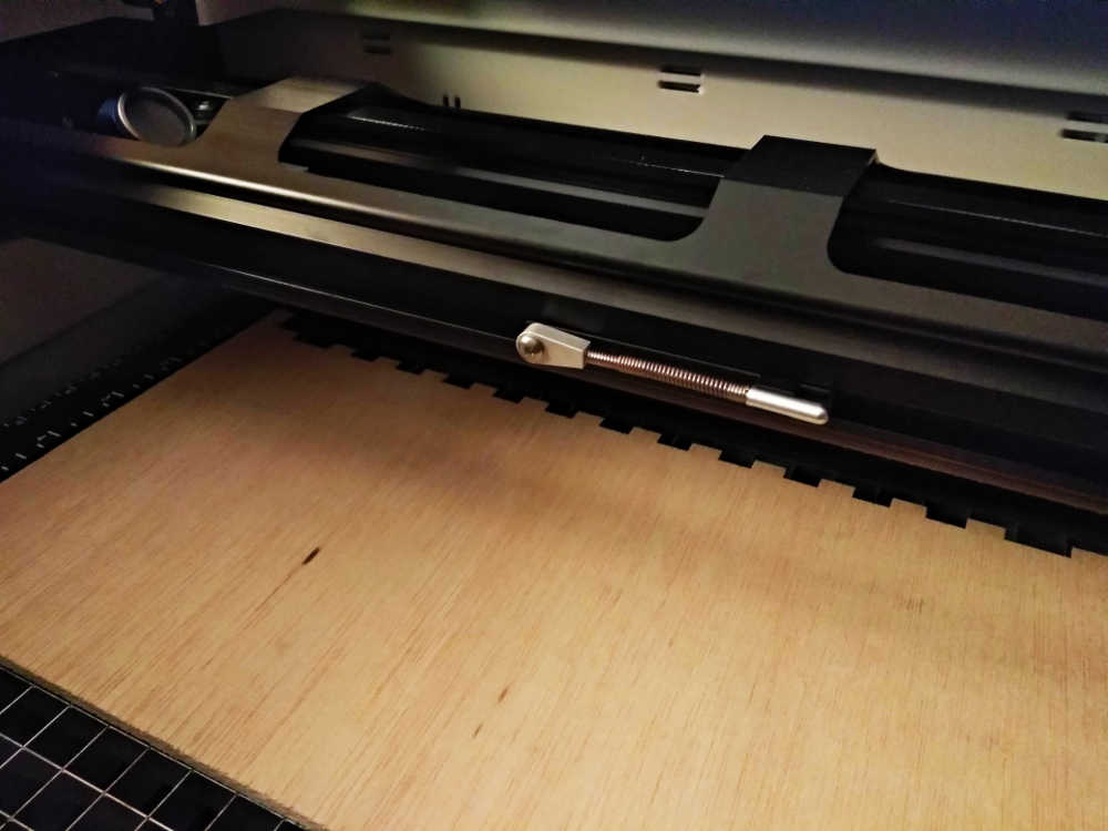
Making sure to put it back in place...
Characterize lasercutter's power, speed, rate, kerf, and joint clearanceI have now prepared most of the designs I would like to try with different materials.
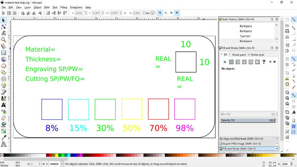
For the laser material test file, I have given up on the full design I selected earlier (18min), I need something a little faster, so I made my own version of a small test strip with inkscape (FILE.svg). This will help find general settings for engraving and figure out the kerf...
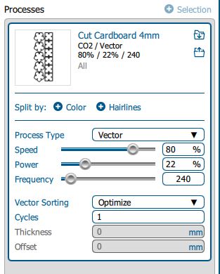
So let's go to "print" and "split" the composition by colors into layers (in the epilog suite), assign the different processes required for each layer (color).
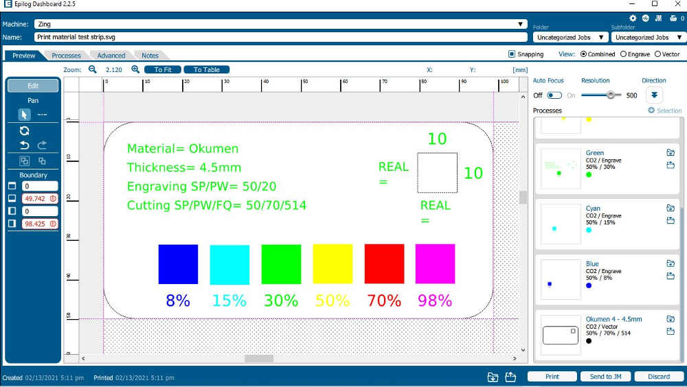
By clicking on a layer you can ajust the settings
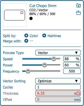
NOTE: I have left space to fill in the real physical dimension compared to the ones from the drawing. This, to figure out the kerf. Also I am for now leaving the speed of engraving at 50 but I know now that I can get it darker slowing down and deeper pushing the power up. For the frequency (vector/cutting/marking), I usually think that the less I want to char the lower the frequency, then it needs to be adjusted in function of the result required and material used (more tests need to be done with a particular job in mind for that).
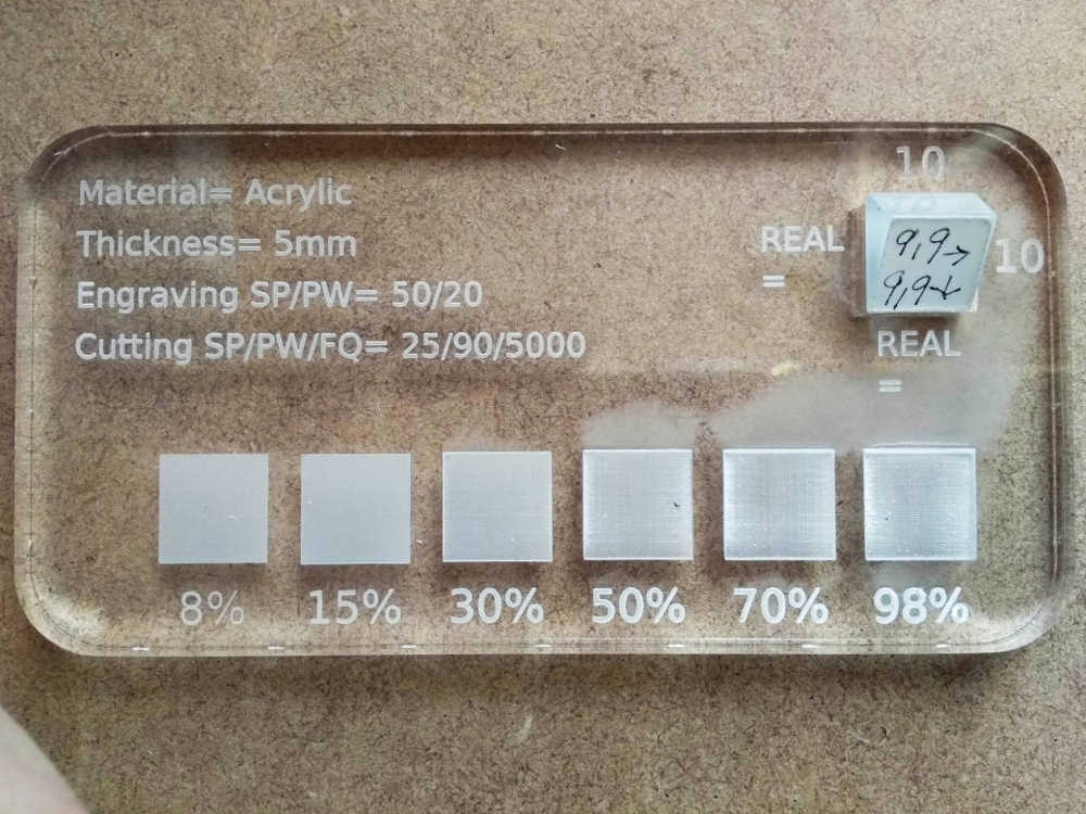
For cutting I use a similar approach, with wood for example, the frequency could go as low as 500 trying to get the cleanest cut. With Acrylic that has a higher density and to get a nice flame polished surface, the frequency could go as high as 5000. All this also depends on the thickness of course and we have the speed and power parameters to ajust for that.
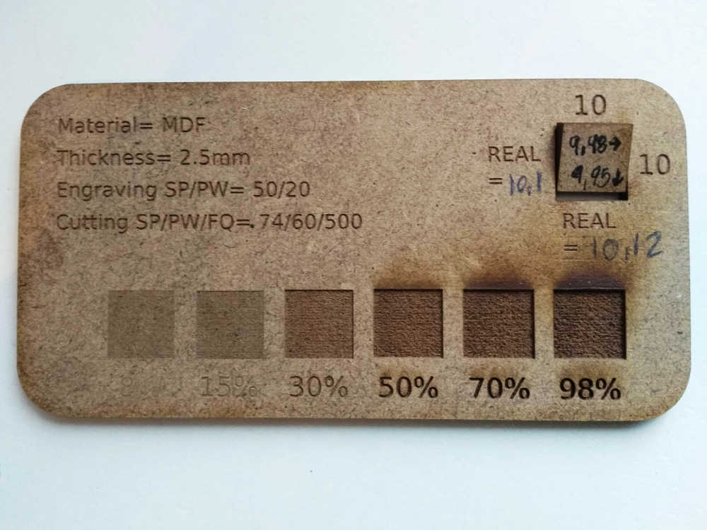
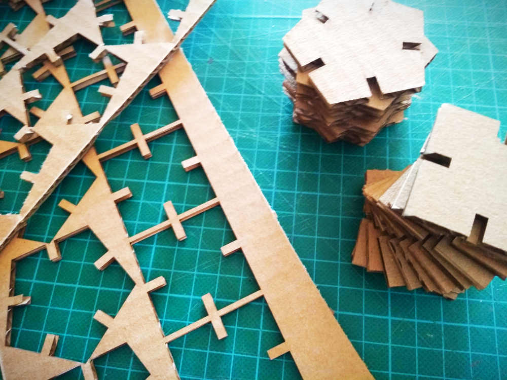
Here are samples from a few materials.
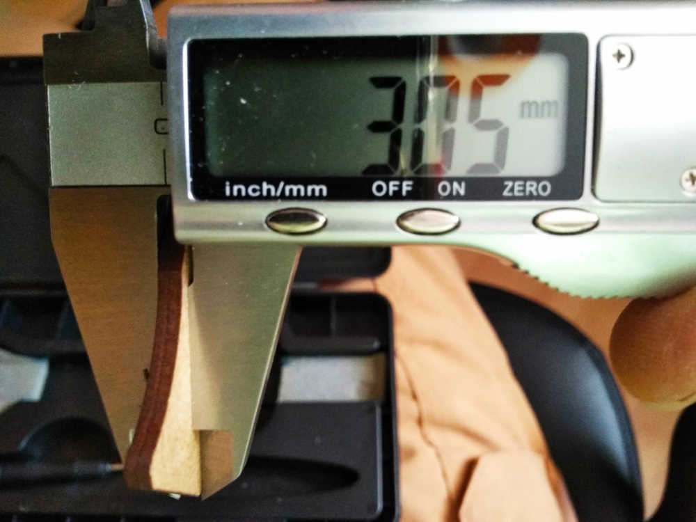
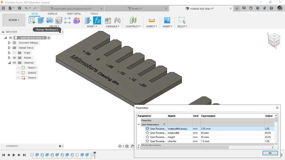
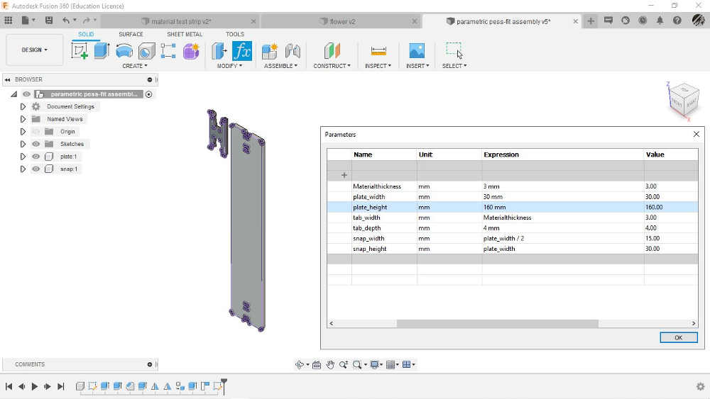
The comb design I made is to be used with different materials, soft or hard, and figure out the best fit for our design. Since the design is parametric, I left the thickness out (indication/engraing on the card) and it should be measured and entered in fusion before exporting the .dxf. (FILE .svg + fusion 360 project file, and in Thingy)
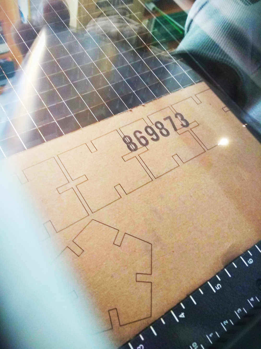
- For Example, the material I am about to use is MDF and it has an overall thickness of 3.05mm, that is what I will enter in the fusion file.
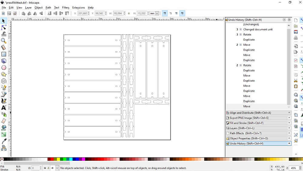
Project the faces on to a new sketch and export that sketch in .dxf. Open it in inkscape for processing to the epilog suite…
NOTE: Caution with the .dxf file from fusion into inkscape, if you have a lot of nods (text or curves) and separated lines needs to be unified/combined (it makes it easier on inkscape to manipulate). I am saying that because if by mistake you projected an entire body onto the sketch you will have duplication (check while in inkscape to be sure).
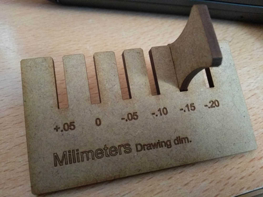
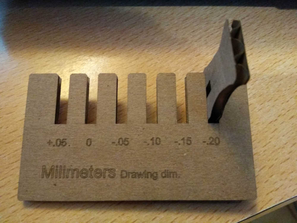
Here is the result...In this case, I feel I have a nice fit: easy to put together but not locked in place (easy enough to dismount also), removing a .15mm to my design dimensions.
I also cut one in the cardboard, which turned out to be -0.2, clearly because of the lower material density (I thought it would have needed more…).
Although this machine seems to be doing a clean job with the parameters I set up, I am not a big fan of corrugated cardboard in the laser machine, it's hard to determine if it is on fire or not.
Go to:Group assignment Parametric design individual assignmentVinyl cutter
Parametric design
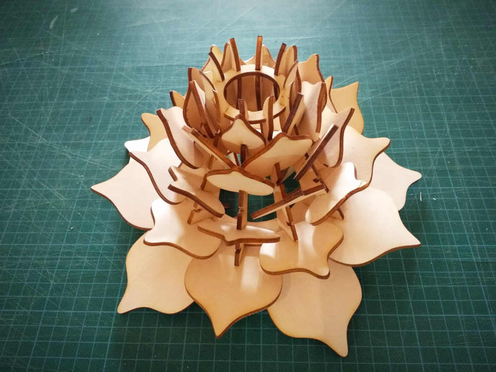
For the press-fit I selected two particular designs that I wanted to try and replicate.
I found this one very interesting, I started to design it in place but It was messy and I wanted a usable file for the laser. I ended up designing a flat version to do some testing first. So far the thickness can be adjusted but keep in mind that the thicker the longer… I have yet to try the bending simulations with fusion.
Let's test it and see how it bends/breaks different materials
As predicted things have broken, I need some time to adjust it, the long pieces need to be longer and the small ones, not as tall, I think if I get the right dimension for the material used it could actually work…
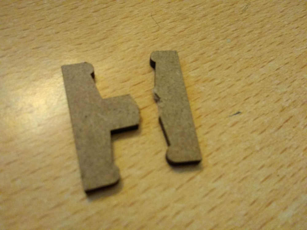
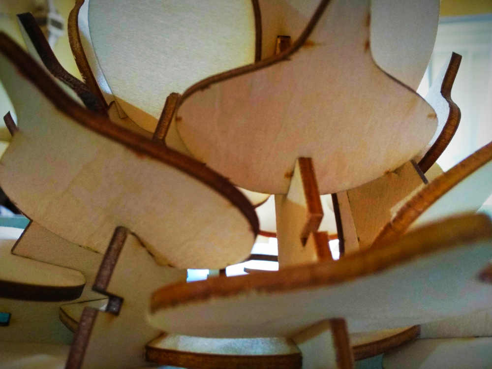
After playing a little with dimensions, the next test was fairly successful and I have managed to put a few pieces together.
.jpg)
.jpg)
Here is the Fusion360 project and the .dxf file
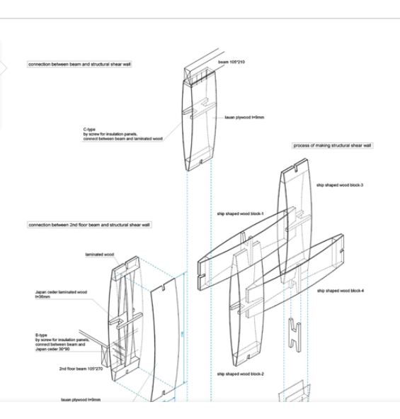
This second one is more attractive but also quite complex. I have managed to have parameters working for the material thickness but I need to spend a bit more time tweaking a few things. Let's see if I get a chance to cut it soon.Here is the design process and how the parameters work.
I have been having trouble exporting the design from fusion, the curved shape does not show on the dxf file, I´ll have a go at it again tomorrow.
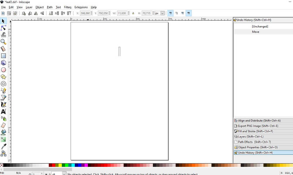
Update: The curves are actually there but it looks like the dxf import is not working properly...so far, the only software that allowed me to process the dxf out of fusion is RDworks and it would have been fine if I was using our other laser machine. I actually tried to save as .ai from rdworks and reconvert that ai file into svg but no luck at all…
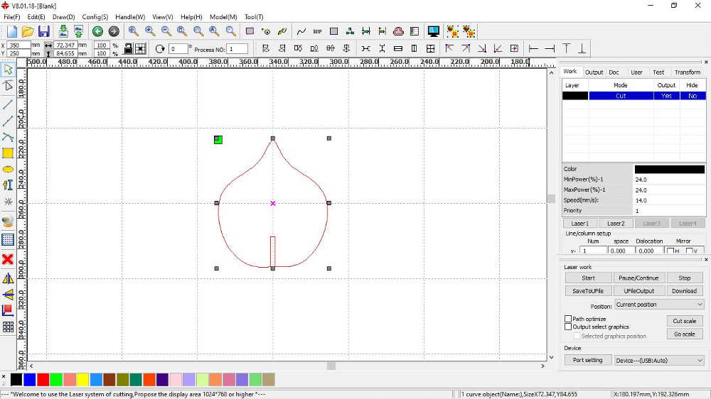
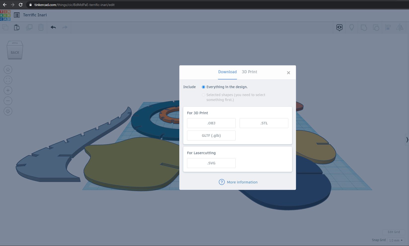
...but I want to be able to do it with the epilog. So, even if I don't particularly like this solution, the only way I find (And I tried quite a few combinations and software) to get the design from fusion to the epilog is to export the stl file from fusion, import in tinker cad…
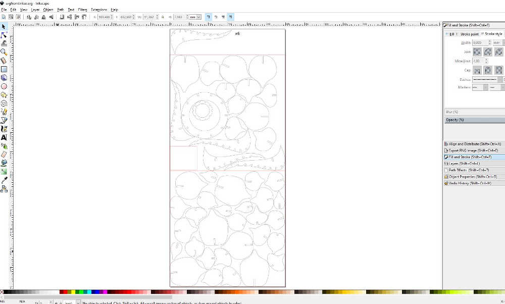
And export again as .svg to finally go to inkscape and find the complete path that can be sent to the epilog.
I feel like fusion may not be the best tool for the job, (at least with the education licence) some feature like "arrange" are not available... A long way from being straightforward so far...and than again I may have made some errors with the curves in my design...
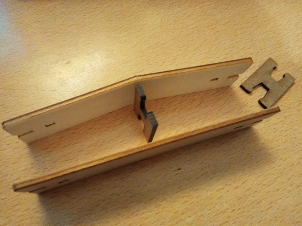
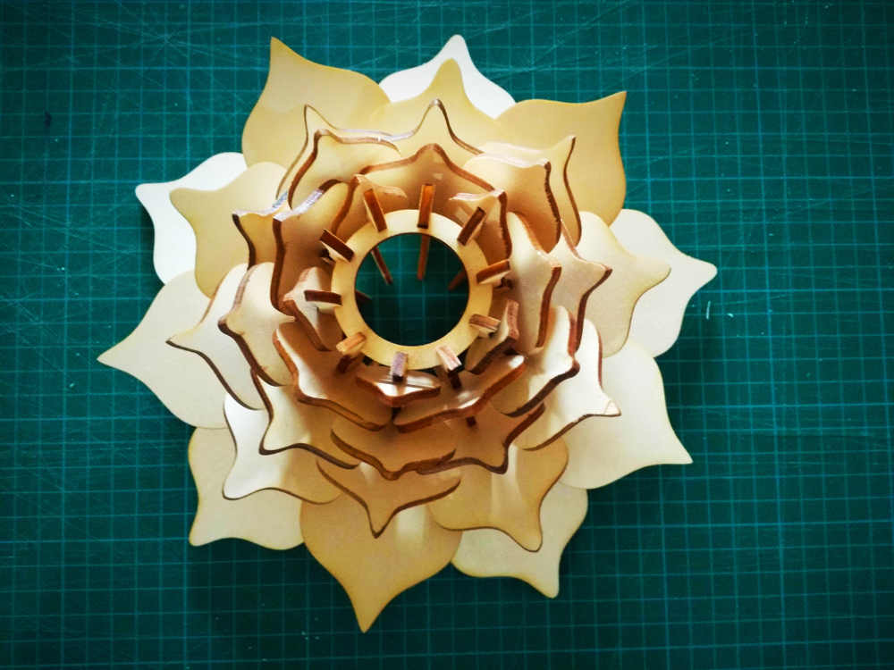
Here is the result, did not get a chance to timelapse that one (technical issues, my phone battery...) but it fitted fairly well, I just wish I would have made it a little bigger.
The fusion360 project file and the .SVG
Here is a third one that I wanted to be able to do in fusion, the idea is to be able to control the sides of the peice beeing create along with the slots and create different parts for a modular composition.
Here is the Fusion 360 project file
And a little video...
Go to:Group assignment Parametric design individual assignmentVinyl cutter
Vinyl cutter
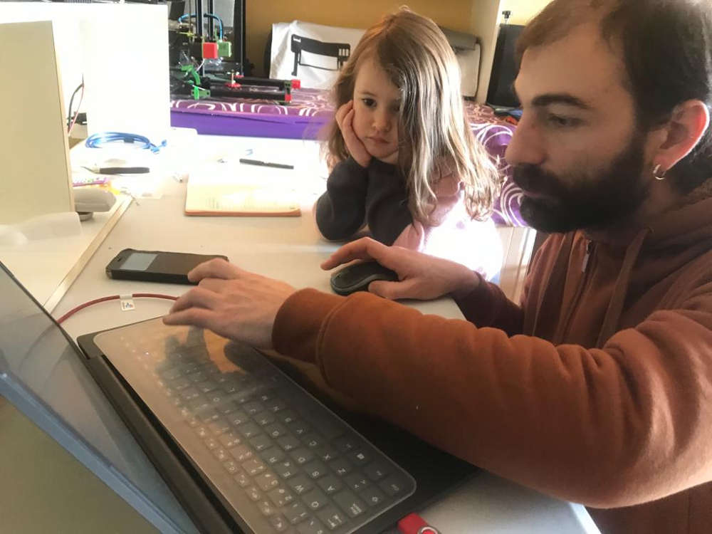
We spent the morning with my niece and together we designed and decorated the place a little…
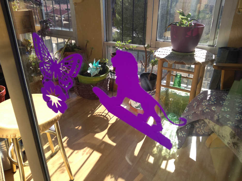
While she kept busy I also cut a design sent to me for the window of a salon de jeux (table game/coffee tea place in france) in two different colors. I will have to wait until they receive it to see it in place.
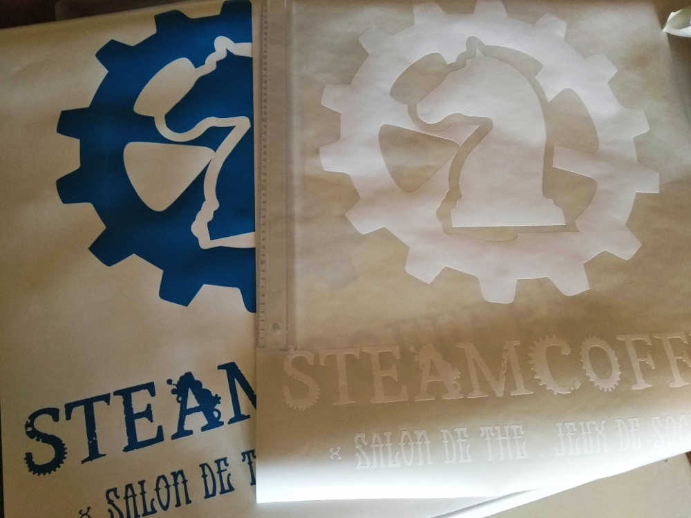
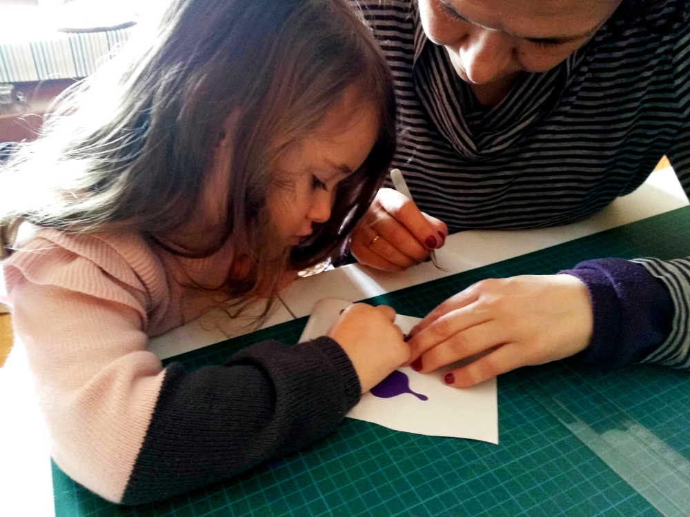
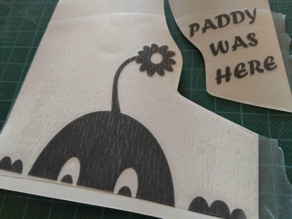
Peeling vinyl, very satisfying...
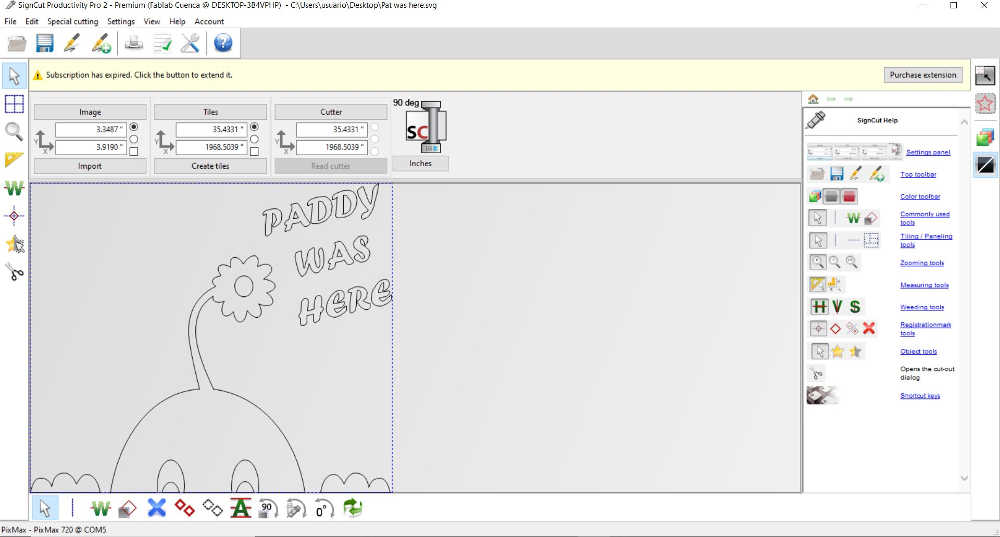
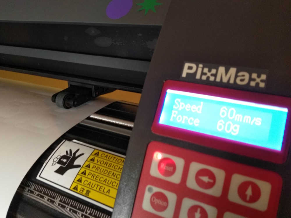
The plotter I am using is a Pixmax that takes material rolls up to 600mm width, it uses the Graftec type blades and comes with Signcut pro software (That is pretty good to set up jobs). It provides tools for contour cutting and other little goodies like adding weeding lines to the composition...I design and send the jobs straight from inkscape (plot extension), so I did not use it often so far.

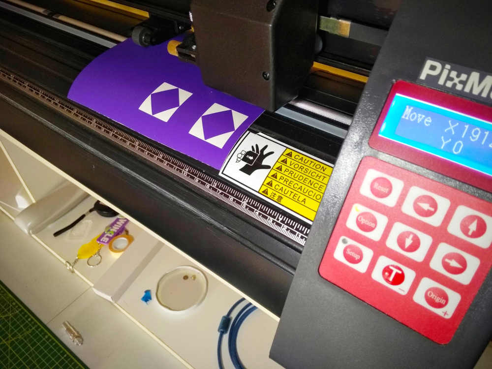
I couldn't help myself and I design a quick sticker to put on the machine...
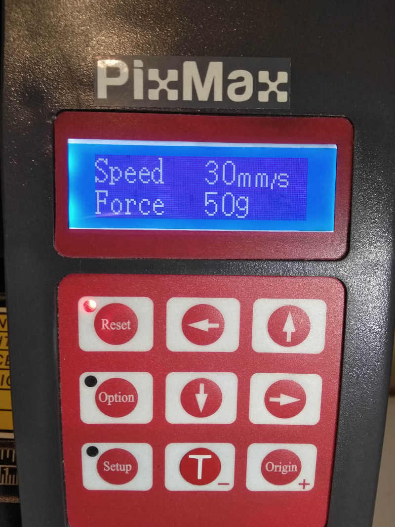
The screen shows the actual speed and force and for the design and material I am using, 60mm/s with a down force of 50,60g seems fair. Usually, I do a quick test cut (test/"T" button), for vinyl, the idea is to cut the material but leave the backing paper intact. For the speed the bigger the scale of the design, the faster I allow myself to cut, the smaller the job the slower the speed usually result in a much cleaner cut (like every machine, it has its limits). The panel is fairly self explanatory, from there you can set the origine of the job, pressure and speed before sending it through inkscape (in my case).
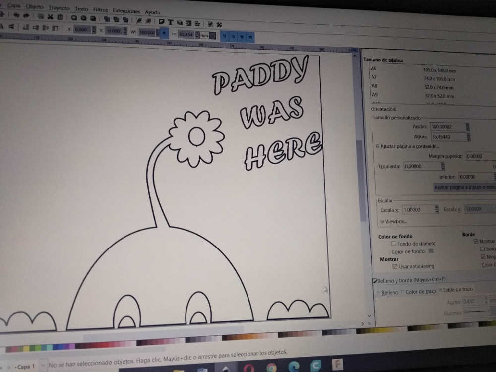
I designed it in Inkscape
Apllying transfer tape, I separate the text to reposition it (I prefer it that way)...
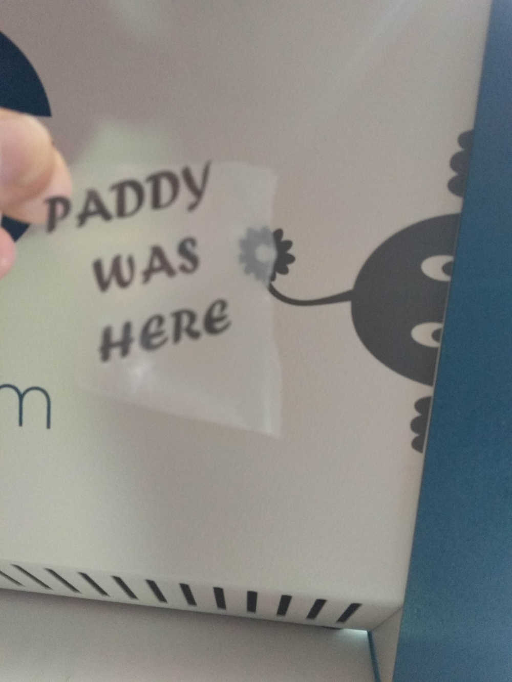
Here is how it turned out.