Embedded Programming
WEEK 08
(17/03/2021 15:15 p.m.) Wednesday afternoon. I am euphoric and scared at the same time. For the first time, I have volunteered to expose my work from Week 07 to Neil. 😱 At the beggining, I wasn't quite sure about showed him the wreck I did with the mannequin leg pieces, but my instructor, Adrián, encouraged me to show it 💚😘.
I think it was great! I got a little nervous at how fast Neil navigated my page and how slowly I was able to gesticulate the words in English.🤣🤣 But it was quite an experience to be able to speak personally with him.😊
This week, we have another of my biggest challenges, Programming!
Chan, chan, chan (dramatic sound).
As I have introduced you in previous weeks, electronics and programming are my Achilles heel. Last year I had my first contact with their, and I know some basic concepts. But since it is not something that I usually do, there are certain things that I have forgotten and I have to refresh. 😅
We will see how the week holds for us! 🙃
(18/03/2021 11:47 a.m.) Like my first Hello Piña! It doesn't seem to work, I'm going to try to make a new board for this week. Over the weekend, my instructor, Nuria, has promised to help me see what happens with my first course 💚😍. We hope everything goes well. 🤞🤞
Unfortunately during the week we had a drop in our crew. Our crewmate Mauro, is ill and is having a bad time.😢🤒 We are all waiting for him, that he recovers and we can enjoy his company as soon as possible 💚.
As this week looks like it's going to be a emotions carousel, the week´s song begins with a rock classic, Bohemian Rhapsody by Queen 🕺.
Is this the real life?
Is this just fantasy?
(...)
Because I'm easy come, easy go,
Little high, little low
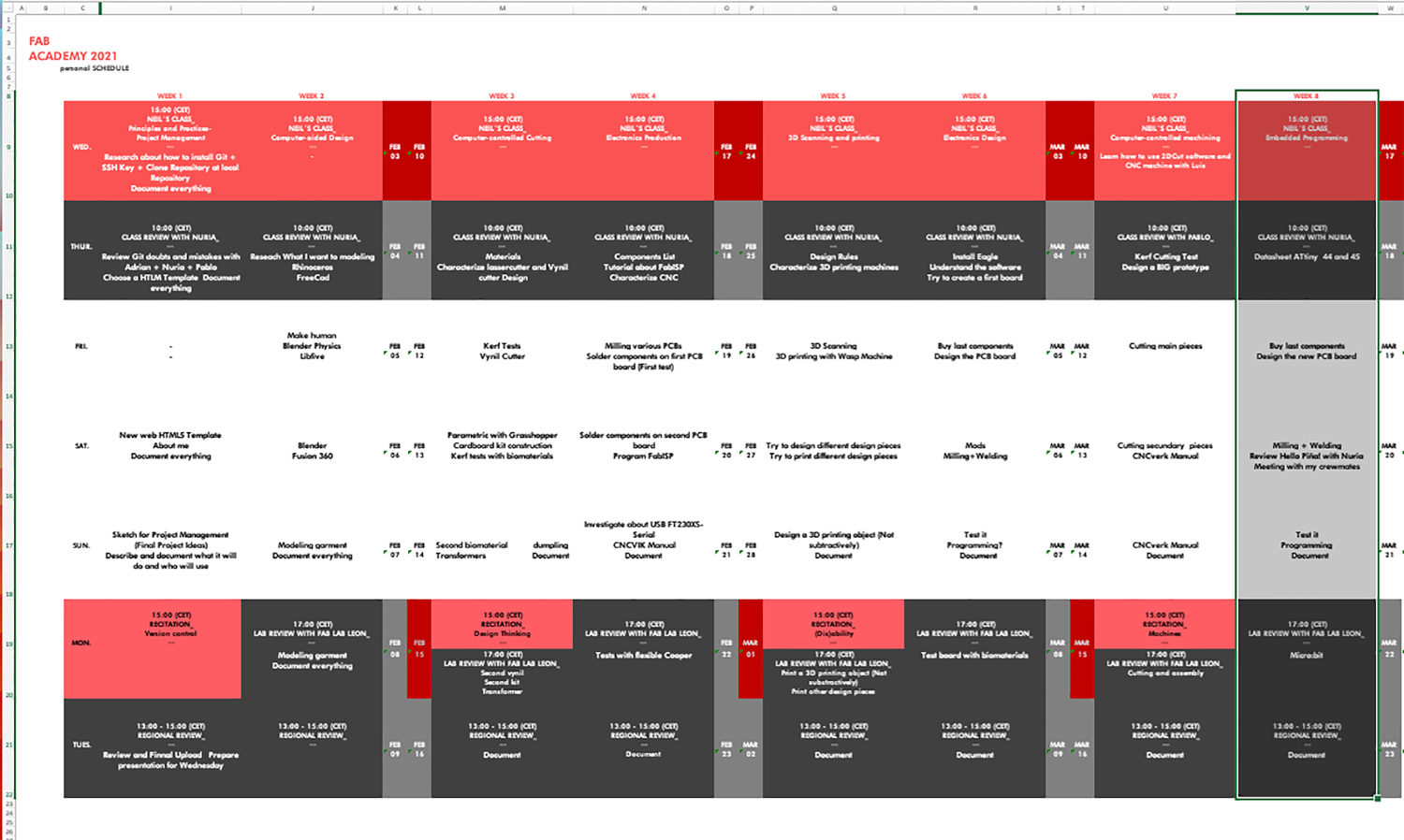
Organizing tasks
Like previous week, we have two types of assignments, one's group and other individual. So as usual, I organize my schedule and here the following Evaluation Criteria that we have to approach to complete the Assignment:
- ✓ Compare the performance and development workflows for different microcontroller families
- ✓ Document our work
- ✓ Read the Datasheet for the microcontroller you are programming.
- ✓ Programmed our board
- ✓ Program the board we have made to do something, with as many different programming languages and programming environments as possible.
- ✓ Described the programming processes we used.
- ✓ Included our source codes.
Extra credit
- ✓ Include a "hero shot" of our board
Group Assignment
- COMPARING OTHER ARCHITECTURES_ micro:bit
A year ago, during my electronics training as a fashion tech designer, we learned to program and know the basic programming skills with these little boards.
micro: bit has several Hardware versions. In my case, I have version v1.5.
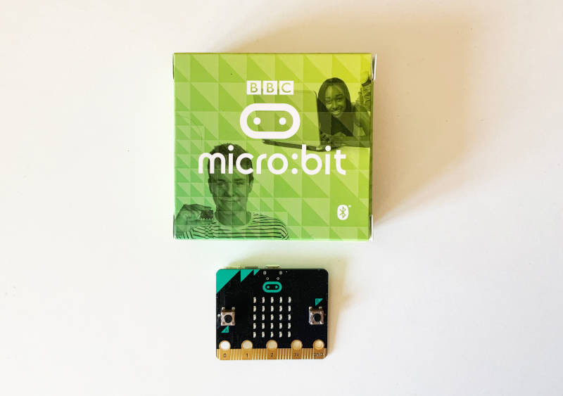
According to the Datasheet of this type of micro:bit has:
- nRF51 processor, model Nordic nRF51822-QFAA-R rev 3
- Arm Cortex-M0 32 bit Core Processor
- 25 Leds Matrix
- Light Sensor
- 2 Button Switches
- 25 I/O pin connectors, 5 of then are oversized to connect 0, 1, 2, 3 V and GND with crocodile clips
- Temperatura Sensor type on-core nRF51
- Accelerometer and magnetometer chip model LSM303GR
- Radio communication Micro:bit Radio
- Bluetooth communication support
- USB connection
- Power Supply operating between 1.8-3.6 V
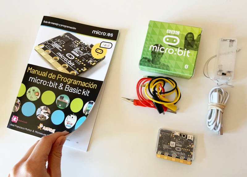
Inside the micro: bit pack came an illustrative basic manual (in spanish) that details the characteristics and possible challenges that you can perform with the board. It is ideal to introduce children and young makers to the use boards and programming.
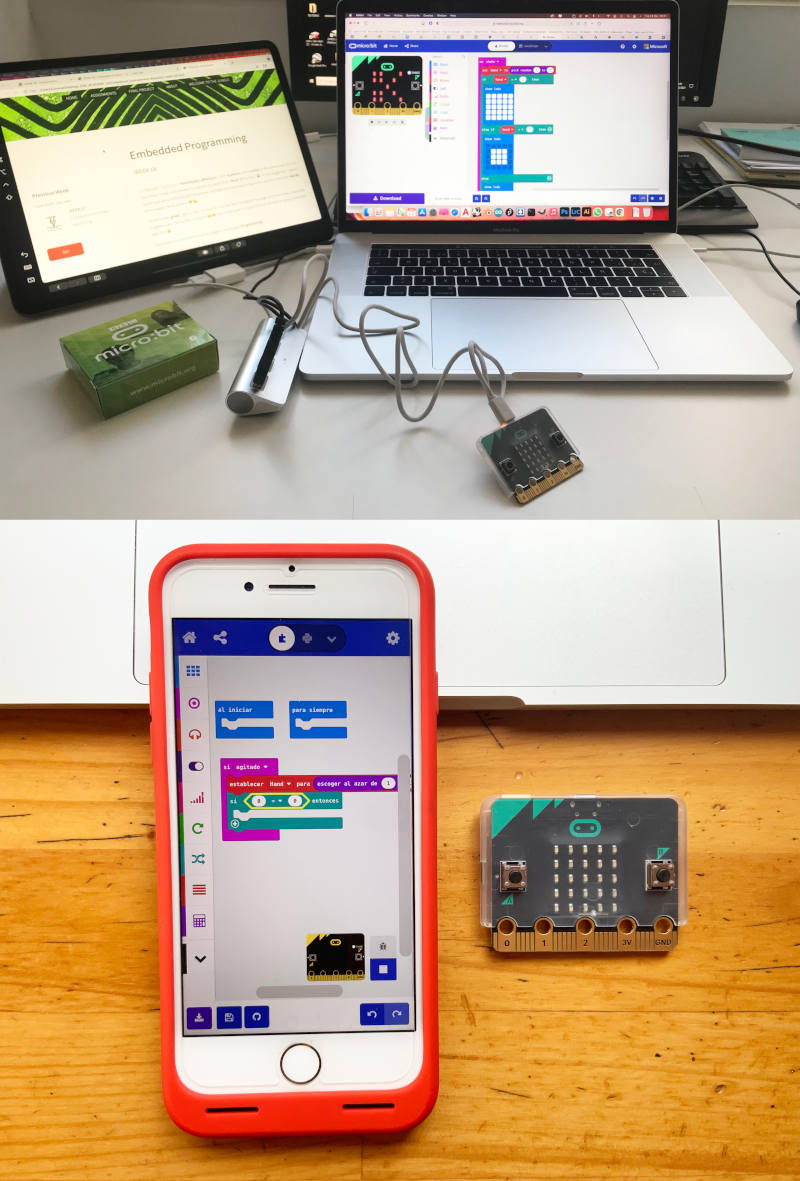
To program micro: bit we can do it: online on our laptop through micro:bit Editor or through our phone with the micro: bit app .
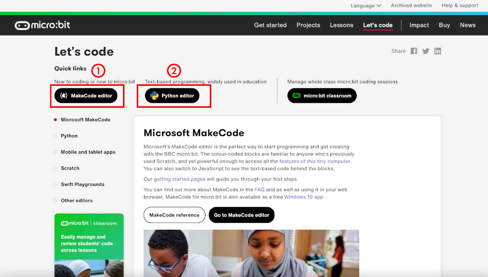
Another advantage to be able to program these boards is we can use different programming languages. micro: bit allows programming from illustrative blocks (MakeCode Editor), JavaScript and microPython (Python Editor).
When we start to program something with the MakeCode editor, we can automatically see on the right tab how this code is transcribed into Java. This is not the case with Micropython. Python's online editor is separate from these two code editors. With which it is necessary to have previous knowledge of Python if you want to program something (from zero) to micro: bit boards.
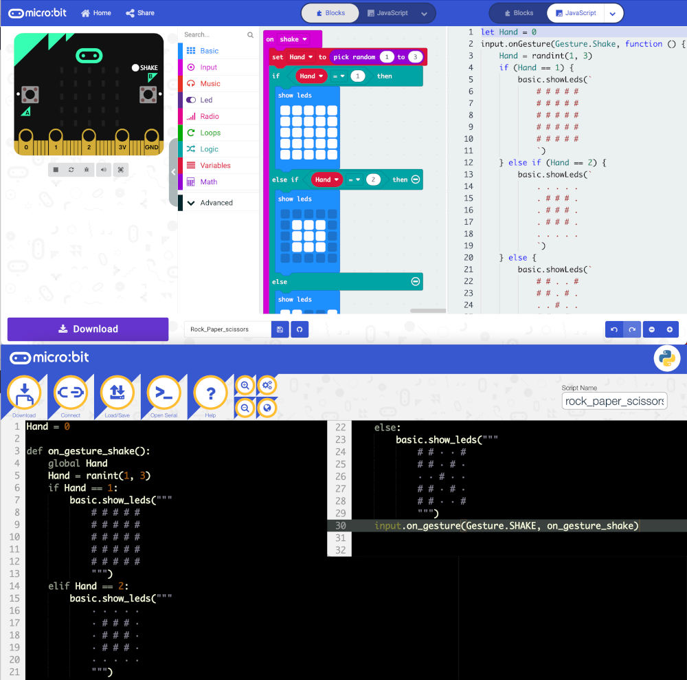
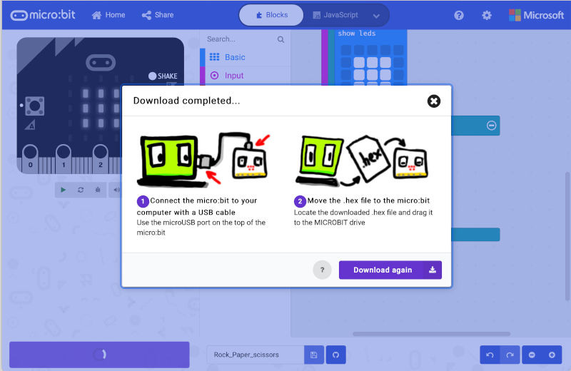
Once I have finished writing our code, I click on Download and a .HEX file is automatically downloaded to my computer.
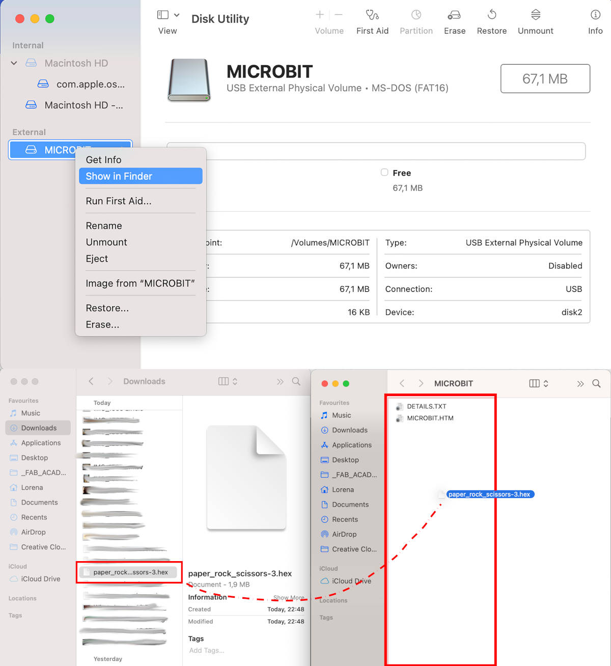
In my case, as I have a Mac OS, when I connect my micro: bit to the USB port of my computer, the external device does not appear directly. In order to access it, I have to go to: Applications > Disk Utility, and here a window will appear telling us which external devices we have connected.
We right click on MICROBIT and select: Show in Finder.
When we have located the folder of our micro: bit, we drag the .HEX file that we have generated to the micro: bit folder. After a few seconds, the file will load.
Here you can see a short video using the Shake utility to make a little game of Rock + Paper + Scissors. HEX 😊😊
On the other hand, I wanted to test how worked, can create and export a programmable code from my phone. As I have an iPhone, I had to use a female-female USB connector to connect my micro: bit with my mobile. Unlike the computer, our mobile does not power the board while we have it connected. So we have to connect it with the external battery that came in our micro: bit package and follow the app reset instructions to recognize our micro:bit on the phone.
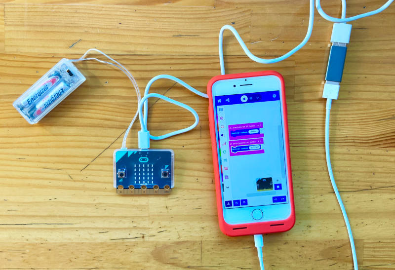
One of the advantages of creating code on our mobile is MakeCode Editor can transcribe directly to JavaSript and Python languages. For beginners, like me, this utility is very useful for the future to be able to understand and know basic knowledge of the Java and Python language.
In this video you can see how we can navigate in the different languages through the different app tabs:
This time, we have made a very simple code to use the buttons. To load the file to our micro: bit, while the mobile sends the code, we must press the three buttons: RESET, A and B for the code to load.
Here you can see a short video where micro:bit greeting the boards of my individual assignment 🤣👋:
Individual Assignment
COMPARING DATASHEET: ATtiny45 AND ATtiny44
For this first part of the individual assignment we have to read the Datasheet of the microcontroller that we are going to use. The datasheet of each tinyAVR controllers describes the components and functionalities of the features that it offers. These documents have between 200-400 pages 😱😱. I'm scared! So I need to be resolutive and read the most relevant parts of the document.
Since I have worked with types of microcontrollers, I am going to read the most significant parts of the: ATtiny 45 and ATtiny 44.
(21/03/2021 8:48 a.m.) This is the first time that I have read a document of these characteristics, and I admit that I have a hard time understanding some concepts which I am not familiar 😅. However, while I read the datasheets, I rely on documentation from other Fab Academy alumnis and on external pages that explain in a more personal way some of the concepts that I must understand.
-
_ATtiny45
The ATtiny45 is a type of microcontroller belonging to the tinyAVR 25/45/85 family. This microcontroller is composed to:
- AVR Core processor
- 8 pins Package
- 6 General Purpose I/O Lines
- One internal clock from 1 to 8 MHz
- 8-bit Timer/Couter and 2 PWM Channels
- 8 KB Flash Memory
- 512 Bytes EEPROM
- 256 Bytes SRAM
- Maximum Voltage: 5.5 V
- Minimum Voltage: 2.7 V
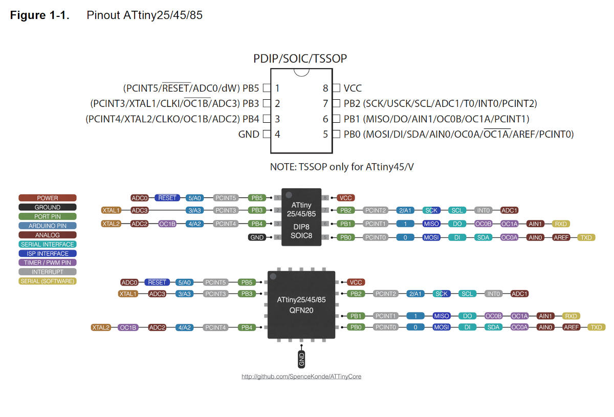
With the help of Datasheet diagram the Datasheet diagram from SpenceKonde webpage, I find out the functionality and possible uses of each of the pins:
- Power voltage: VCC
- Ground: GND
- Analog Pins: PB5, PB3, PB4, PB2, PB1, PB0
- PWM Pins:PB4, PB1, PB0
All I/O pins are configured with internal pull-up resistors.
Regarding of communications, there are two types of protocols that we can use depending on the funcionality that we are going to give the microcontroller. It is not possible to use both two at the same time, since on some pins they coincide at the same time.
- Serial Peripheral Interface (ISP): PB5 (RESET), PB2 (SCK), PB1 (MISO), PB0 (MOSI)
- Serial Software: PB1 (RXD), PB0 (TXD)
-
_ ATtiny44
The ATtiny44 is a type of microcontroller belonging to the tinyAVR 24/44/84 family. This microcontroller is composed to:
This microcontroller is composed to:
- AVR Core processor
- 14 pins Package
- 12 General Purpose I/O Lines
- A crystal/resonator oscillator
- One internal clock from 1 to 8 MHz or/with external crystal or clock up to 20 MHz
- An 8-bit Timer/Counter with two PWM channels
- A 16-bit timer/counter with two PWM channels
- 4 KB Flash Memory
- 256 Bytes EEPROM
- 256 Bytes SRAM
- Maximum Voltage: 5.5 V
- Minimum Voltage: 1.8 V
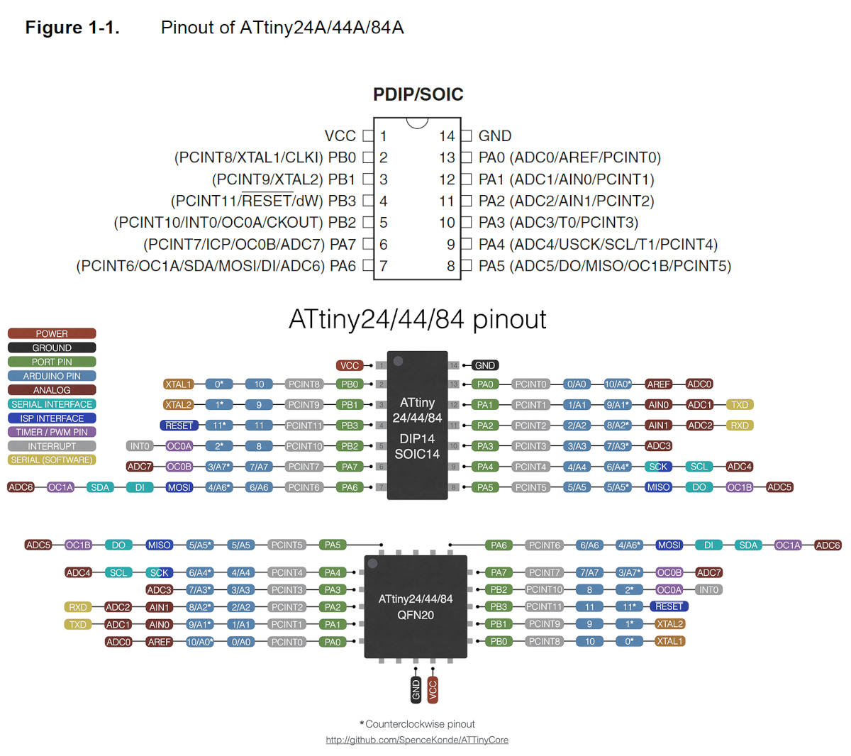
Again, combining the original Datasheet diagram with the ATtiny 44/84 diagram from SpenceKonde webpage, I find out the functionality and possible uses of each of the pins:
- Power voltage: VCC
- Ground: GND
- Analog Pins: PA0, PA1, PA2, PA3, PA4, PA5, PA6, PA7
- PWM Pins: PA5, PA6, PA7, PB2
All I/O pins are configured with internal pull-up resistors (as in ATtiny45).
About the communications, there are again two kind of protocols that we can use depending on the funcionality that we are going to give the microcontroller. In this case, as it has several pins, the functionalities of each communication do not overlap each other.
- Serial Peripheral Interface (ISP): PB3 (RESET), PA6 (MOSI), PA5 (MISO), PA4 (SCK)
- Serial Software: PA2 (RXD), PA1 (TXD)
PROGRAMMING HELLO PIÑA!
(09/03/2021 21:54 p.m.) Two weeks ago, during Electronics Design week, I had the opportunity to design and solder two boards that I made with some ATtiny45 microcontrollers, a led and a switch button. Like the rest of my crewmates, in order to test it I decided to program it to see that everything was correct and working.
But, after several attempts programming with different types of computers, I had an error that was repeated several times:
avrdude: initialization failed, rc = -1.
Adrián and Nuria explained to me that this error (among others) seemed to be a problem with welding. 😦😦
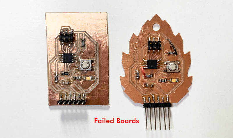
(10/03/2021 14:17 p.m.) Throughout Wednesday morning and part of the afternoon, I checked and rechecked the welds, I changed the ATtiny to check if the problem was with the microcontroller in fact .... but nothing!.
avrdude: initialization failed, rc = -1.
avrdude: initialization failed, rc = -1.
avrdude: initialization failed, rc = -1.
...
😫😫😫😫😫😫
(09/03/2021 23:47 p.m.) This was my mood at the end of that night.😢
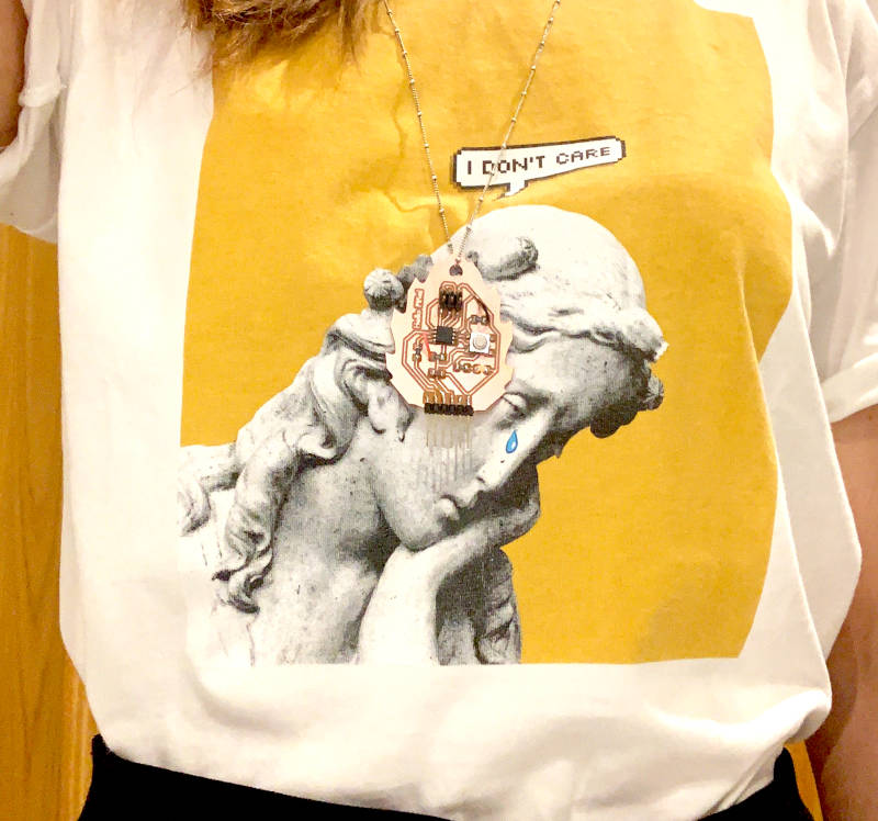
(12.03.2021 9:29 a.m.) After a few days of rest, while we were working at week 07 with the CNC machine, I began to review the design of my board to see if the error could come from here.
When I started to review it and seeing the work that my crewmates had done and compare with mine, I realized that I had not connected the ATtiny RST pin with the ISP of my board. 🙇🙇🙇
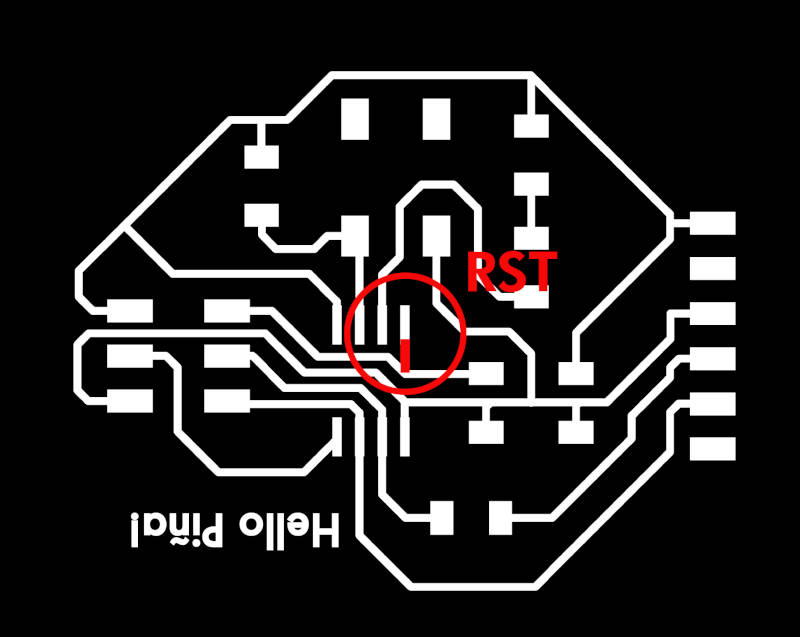
So I had to wire the ATtiny RST pin with the track that connected the resistor with the RST pin of my ISP Header. At the end my board looked like a Frankenstein as my Frankenmannequin from Week 07. 🤣🤣
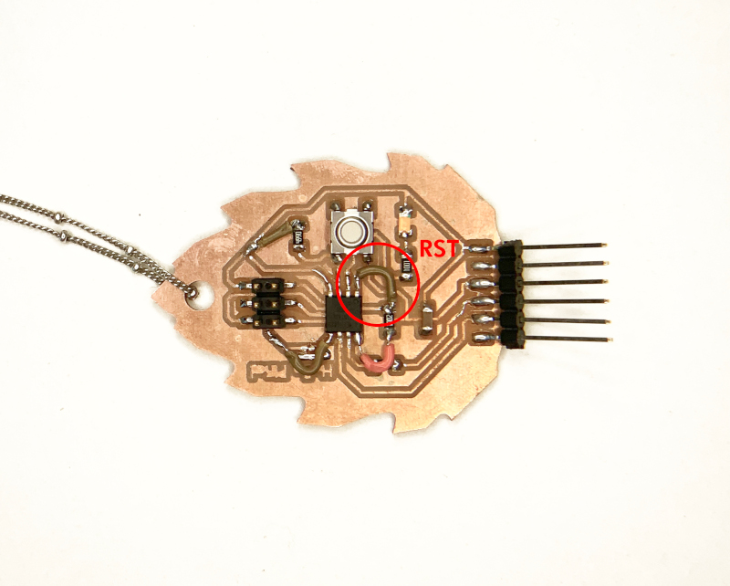
I tried again to program it hoping to finally get it ... but nothing!: avrdude: initialization failed, rc = -1. 😤😤😤
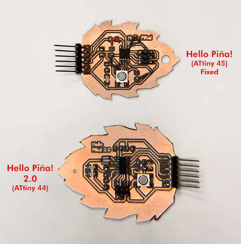
I started to give up 😞, so I decided to try my luck with a new board: the next generation of Hello Piña! 2.0
(18.03.2021 11:28 a.m.) In Thursday's review with Fab Lab Leon, I told to Nuria that my first Hello Piña! it still didn't work. So over the weekend, she took my files and made my Hello Piña! at the Fab Lab Leon.😍🙏
(21.03.2021 20:14 p.m.) On Sunday night, Nuria sent me a short video and her Hello Piña! it worked !! 😱😱😱😱
What could I be doing wrong? 🤔
When she showed me the video, I asked her if she could show me what workflow she was following, to see, step by step what she was doing.
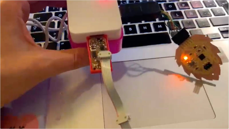
To program it, she used Arduino 1.8.13 without selecting any port or doing bootloader. In my case, without knowing, I selected a port that I did not know what it corresponded to and could not deselect again. So I completely uninstalled Arduino and reinstalled it again.
Once installed, the first thing I do is go to Preferences, and in Additional Boards Manager, I add this URL.
Once added, we go to Board Manager, search for "attiny" and download David Mellis version 1.0.2.
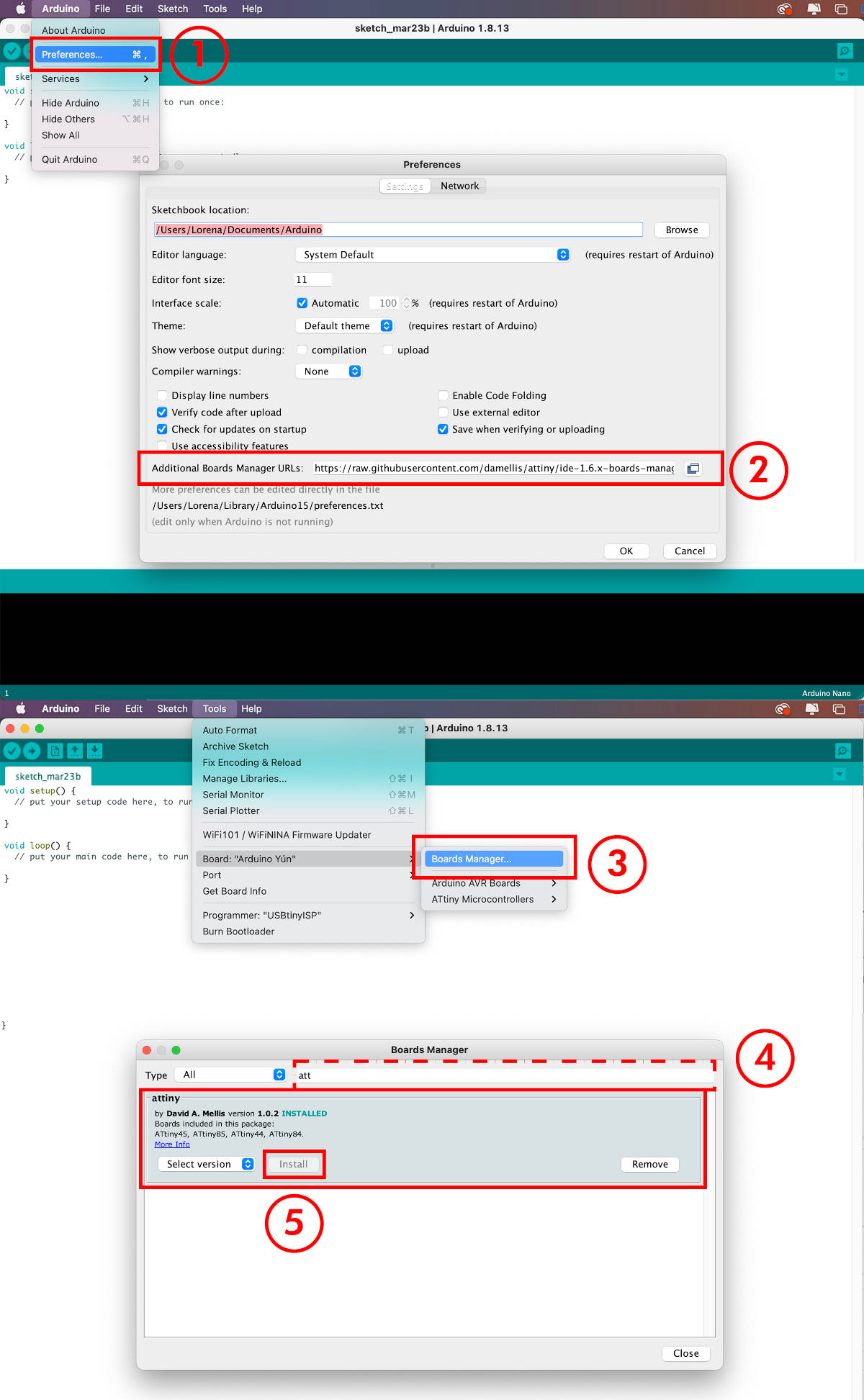
(21.03.2021 20:45 p.m.) I connected my FabISP45 programmer and my Hello Piña! with the flat cable and FTDI cable (correctly positioned). Once placed, in Arduino I use an Blink code example. In Tools I configure my board as the photo illustrates: without selecting Ports and doing not Burn Bootloader. And I give Upload...
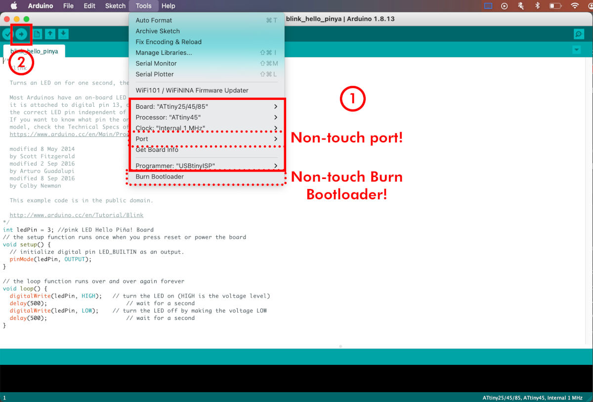
After two weeks, finally ...
HELLO PIÑA! IS RISEN !!!!!!
😭😭😭😭🎉🎉🎉🎉🎉🎉
Thanks so much for the help, Nuria! 😍😘💜
Here you can watch a short video programming an Arduino Blink Example:
Here, you can see other video use the button switch with this Arduino Button Example :
Here I do a performance using both Blink + Button functionalities to test its operation:
DESIGN AND PROGRAMMING HELLO PIÑA! 2.0
(21.03.2021 10:21 a.m.) Last Friday and weekend, before solving the problem related to my first Hello Piña! I started designing a new generation of Hello Piña! using an ATtiny that offered me more functionalities. In this case, in my fab lab we had an ATtiny44, so I decided to make a version 2.0 where I could incorporate more LEDs and / or buttons.
(20.03.2021 17:49 p.m.) During Saturday afternoon, Nuria and I met to talk about the possible errors that my first Hello Piña! could have, in addition to checking the next board design that I had made.
In this review, Nuria advised me that instead of using 1K resistors for the LEDs, she will use a 470 Ω resistor and on the button, instead of a 470 Ω resistor, another 10K resistor, for the best current flow through both components.
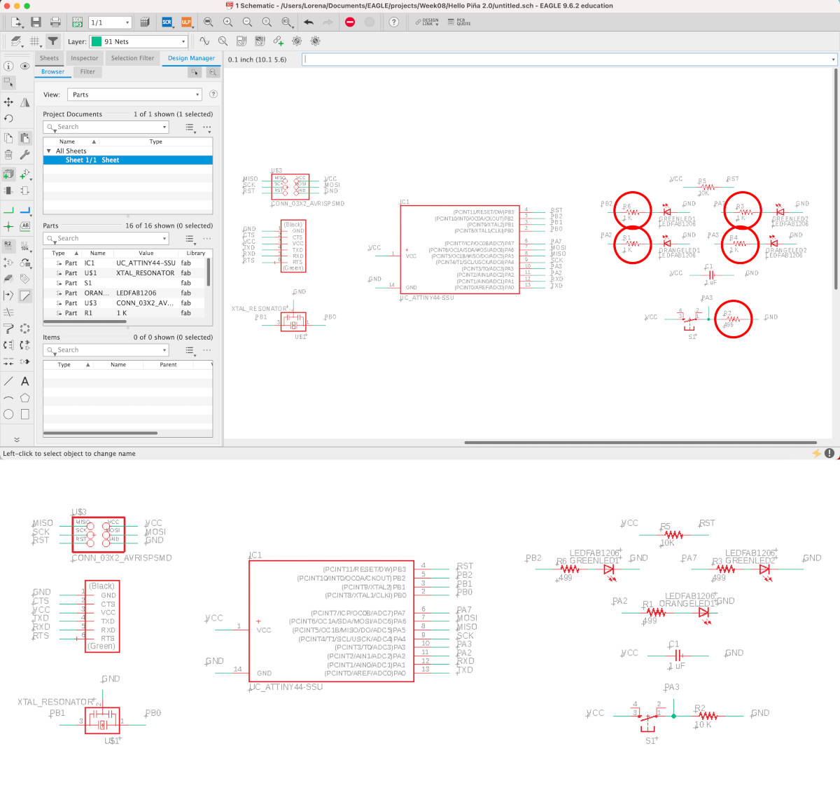
Once the changes have been made, this is the final design of my new board in which I incorporate three LEDs and an external 20MHz resonator.
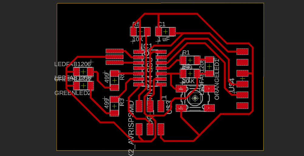
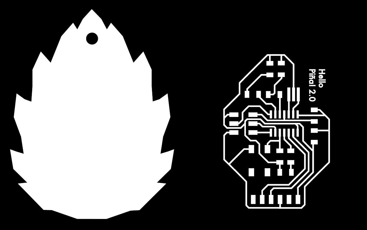
This is the final design of the new Hello Piña! 2.0. Here you can see the files of: Hello Piña! 2.0 Traces. PNG + Hello Piña! 2.0 Outlines. PNG
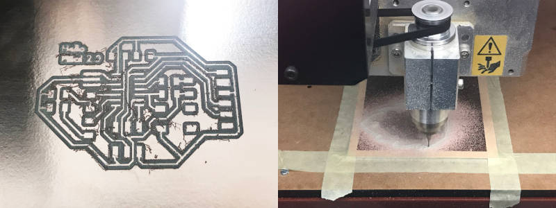
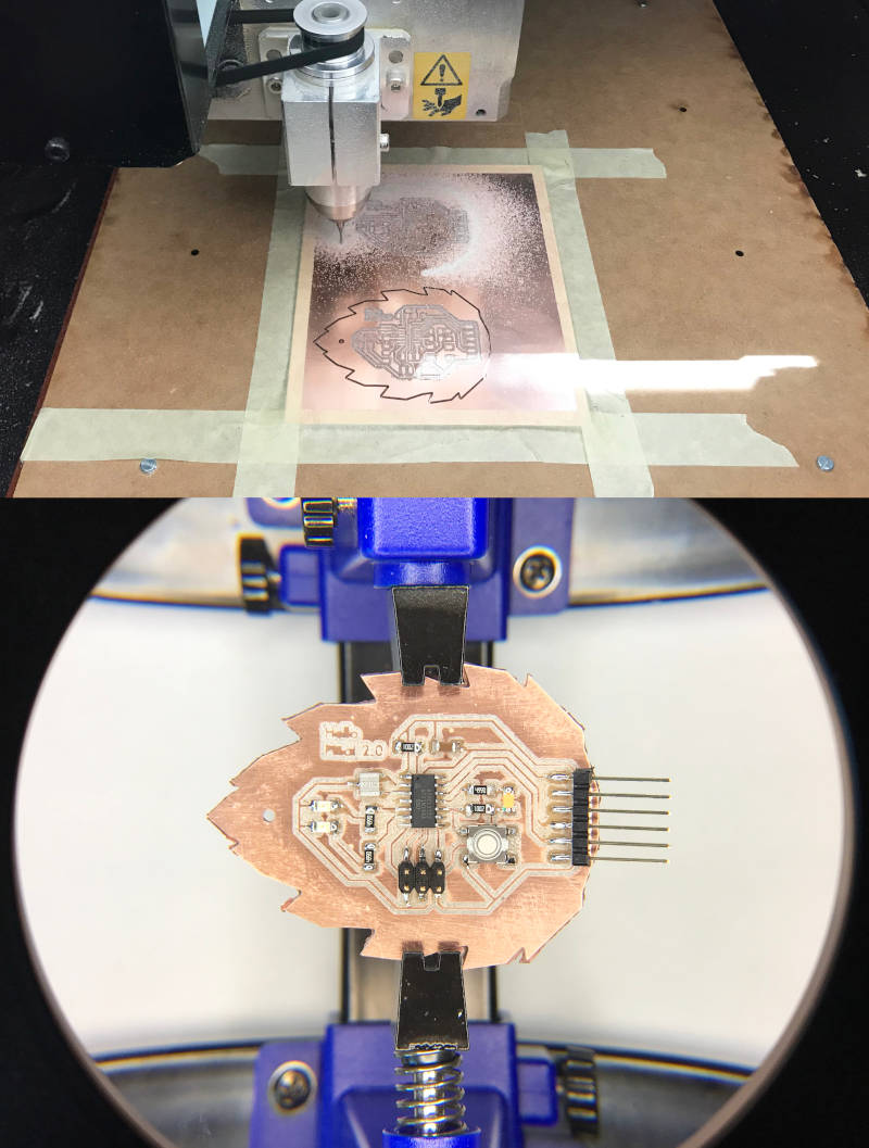
(20.03.2021 11:26 a.m.).On Saturday morning, at the Fab Lab UE Madrid, while Alberto was working on his assignment with the Voltera, I dedicated to milling my board on his Roland MDX-40.
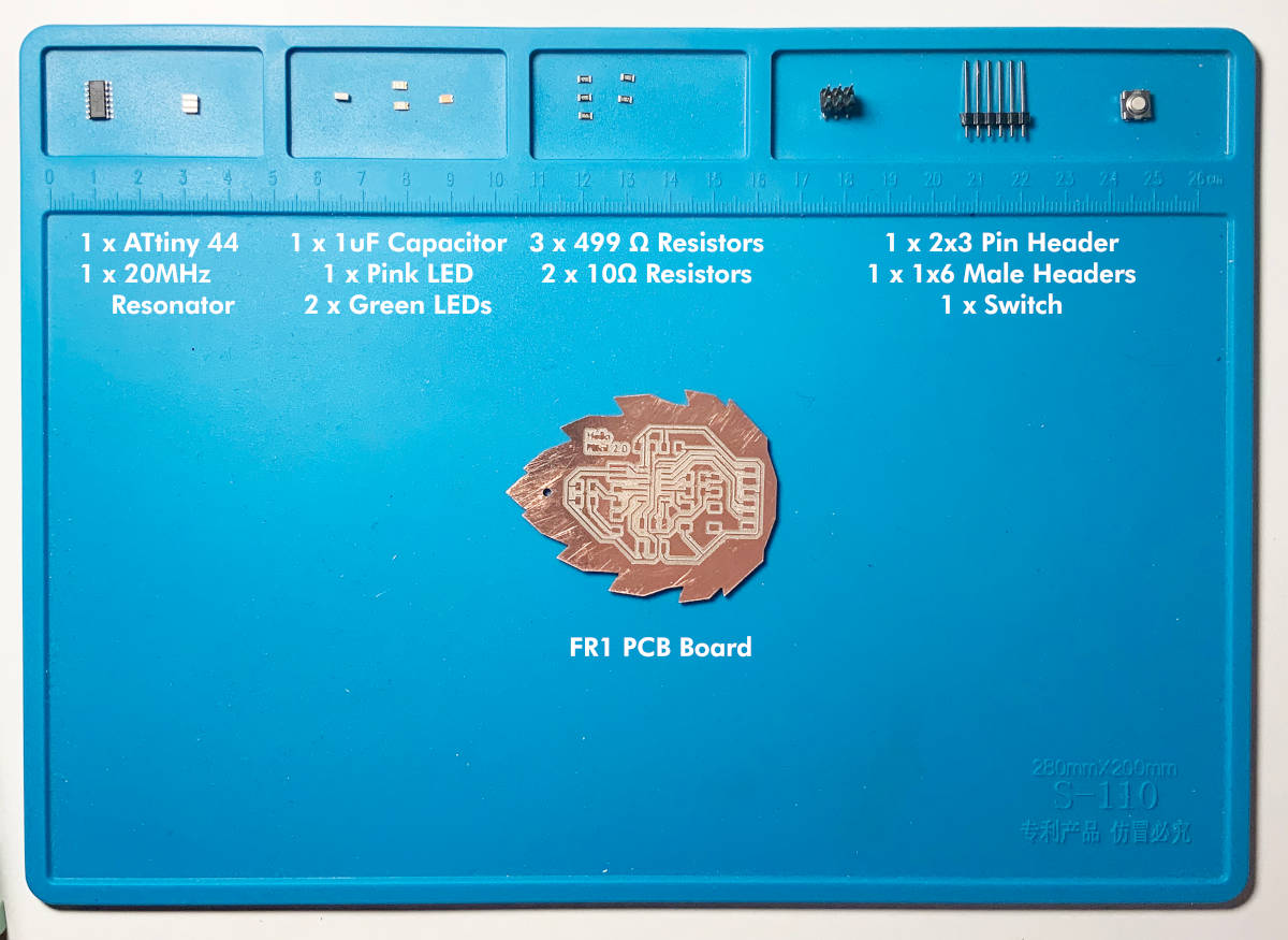
Once milled, to make the board we will need:
- 1x ATtiny44
- 2x 10kΩ resistors
- 3x 499Ω resistors
- 1x 20MHz Resonator
- 1x 1uF Capacitor
- 1x pink LED
- 2x green LEDs
- 1x Switch Button
- 1x 1x6 male header
- 1x 2x3 pin header
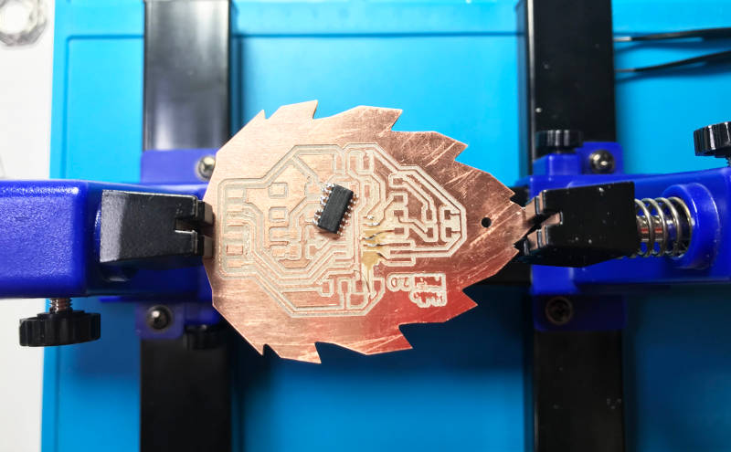
(20.03.2021 21:49 p.m.) One thing I have learned from this assignment is when night it comes, I should NEVER go welding. After the meetings I had on Saturday afternoon, I tried to solder all the components of my board. I started with the ATtiny44 and when I soldered the first 7 pins on one side, I realized that I had the microcontroller on the opposite side. 🤦🤦🤦
When I tried to unsolder it, it was too late, and I broke the traces around it.
(21.03.2021 08:40 a.m.)Sunday morning, I told with Alberto what had happened to me, and he opened the doors of the Fab Lab UE Madrid for me so that I could mill various boards. Thanks my friend! 💚
In the afternoon, and calmly, I finally managed to weld the new Hello Piña! 2.0 🎉
(21.03.2021 21:52 p.m.)In the afternoon after I weld I checked that everything was fine and in place. When I finished, I tried to program the new Hello Piña 2.0! with a little code. But, due to strange circumstances that I was unaware of, the file had been successfully uploaded to my board, but it did not seem to work. 😟😩
Here you can see in this video how was my attempt to program it: 🤷
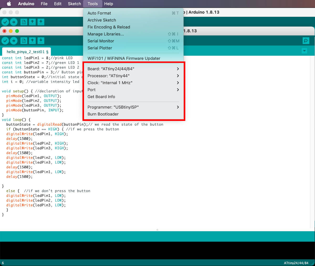
(22.03.2021 11:07 a.m.)The next morning, checking the boards and codes that the rest of my crewmates had made, I realized that I was naming the Arduino pin number with the Attiny pin numbering. 🤦♀️🤦♀️

So, once I have changed the nomenclature of the pins well and I check again the right workflow to program my Attiny 44 board is correct and I click Upload and...
It works!!!🎉🎉🎉
Here you can see a short video, where the LEDs of my new board light up! 😍😍
Finally, this week despite the problems that have arisen along the way, it has been a miracle! I have managed to resurrect my first board design and have managed to program two boards from scratch.
Let´s go to the next step!! 💪💪
FILES
micro:bit
PROGRAMMING HELLO PIÑA!
DESIGN AND PROGRAMMING HELLO PIÑA! 2.0
