Input device
For this week we had to deal with input device.
- Group assignement :
- Probe and input device(s)’s analog and digital signals
-
Document your work to the group work page and reflect on your individual page what you learned
-
Individual assignement:
- Measure something : add a sensor to a microcontroller board that you have designed and read it.
I decided to test a hall effect sensor, needed for my final project.
Group assignement
Hall effect sensor
Wiring
I began by reading about the sensor. Unfortunately our SMD hall sensor wasn’t included in our last electronic order… Probably a mistake on our side. But I manage to get a DIP version of the hall sensor.

The hall sensor has 3 pins. Two for power supply and an output for the value. This sensor is affected by magnetic field. When a magnetic field is close enough to the sensor, the output value will change. When no magnetic field is detected, the output voltage will be half of the supply voltage. If a positive polarity magnetic field is detected, the output voltage will increase. Conversely, the output voltage will decrease is a negative field is approached.
I tested it onto an Arduino board to understand how it works and how to wire it before designing the board.
| Arduino | Hall effect sensor |
|---|---|
| 8 | VOUT |
| 5v | VIN |
| GND | GND |
I tested the board using the embed debug LED. On every Arduino, There is a built-in led accessible on Pin 13.
Programming
#define LED_PIN 13
#define HALL_PIN 8

void setup(){
  pinMode(LED_PIN, OUTPUT);
  pinMode(HALL_PIN, INPUT_PULLUP);
}

void updateLED(){
  digitalWrite(LED_PIN, digitalRead(HALL_PIN));
}

void loop(){
  updateLED();

}
It works has a charm ! But surprisingly, the LED state is inverted… The LED is on when nothing is detected by the hall effect and light on when the magnet is approached.
Moreover, the values seems to depend on the sensor orientation.
Distance sensors
I tried two different distance sensors for robotics application. I’m participating annually to the French robotics cup. During a match your robots need to accomplish tasks. Furthermore, the robot need to avoid opponents. To do that, We are using either a Lidar or other distance sensors.
Here I’ve tried three sensors : - Sharp 0141SK distance sensor - Pololu irs12a Lidar module - Mb6t LIDAR
Sharp distance sensor
The sharp sensor is the easiest to use. The sensor has three pins, GND, VCC and VOUT just like the hall effect sensor. It returns an analog value according to the distance to the detected object.
Here is the code I used to test it :
void setup() {
  Serial.begin(115200);

}

void loop() {
  Serial.println(analogRead(A0));
}
Simple as that !

I plugged the VOUT pin on the A0 analog pin of the Arduino and uploaded the code above.
Using the Serial port I got those values by putting my hand in front of it :
15:47:59.618 -> 220
15:47:59.618 -> 222
15:47:59.618 -> 219
15:47:59.618 -> 218
15:47:59.618 -> 219
15:47:59.618 -> 219
15:47:59.618 -> 218
15:47:59.618 -> 220
15:47:59.618 -> 229
15:47:59.618 -> 220
15:47:59.618 -> 219
15:47:59.618 -> 220
Here is the theoretical curve from the datasheet. This curve present how distance and output voltage are related.

I found a very good tutorial online with a code to convert the voltage into mm. So I tried this code :
void setup() {
  Serial.begin(115200);

}

void loop() {

  float volts = analogRead(sensor)*0.0048828125;  // value from sensor * (5/1024)
  int distance = 13*pow(volts, -1); // worked out from datasheet graph
  delay(200); // slow down serial port

  if (distance <= 30){
    Serial.print(distance);   // print the distance
    Serial.println(" mm");   // print the distance
  }
}
15:59:21.894 -> 4 mm
15:59:22.080 -> 5 mm
15:59:22.266 -> 5 mm
15:59:22.452 -> 4 mm
15:59:22.681 -> 5 mm
15:59:22.866 -> 5 mm
15:59:23.052 -> 4 mm
15:59:23.283 -> 5 mm
15:59:23.468 -> 5 mm
15:59:23.699 -> 4 mm
15:59:25.470 -> 5 mm
15:59:25.702 -> 4 mm
15:59:25.889 -> 5 mm
Unfortunately, the range of this sensor is too low. I need another one…
Lidar module
I bought a LIDAR module on GoTronic This sensor can return the distance of an obstacle in a 0 - 130 cm range.

As you can see the sensors has three pins, one for the VCC, one other for the GND and the last for our data. This sensor isn’t analogic. It use pulsewidth modulation to send the data. Reading it with an analogRead function will return 0 or 1. By order of magnitude, we will manage to read a mean voltage but this is not really precise as

I had to solder three wires to use it with my Arduino. I tined the wires, placed them toward the back the board and soldered everything. Then I plugged the VOUT to the digital pin 2 of the Arduino.
Once the sensor is powered I saw a little LED blinking. The VOUT of this board is also linked to a LED. This LED will get brighter as the object in front of is approach.
| Near | Far |
|---|---|
 |
 |
Even if it is a laser module, we can’t actually see the laser beam for two reason : - It is very weak - It is in the infrared wavelength
But even if our eyes cannot see infrared, our smartphone’s camera can ! So here is the picture of the laser :

Then I read the datasheet and try an example code to read the data. Here is what I came with :
const uint8_t sensorPin = 2;

void setup()
{
  Serial.begin(115200);
}

void loop()
{
  int16_t t = pulseIn(sensorPin, HIGH);

  if (t == 0)
  {
    // pulseIn() did not detect the start of a pulse within 1 second.
    Serial.println("timeout");
  }
  else if (t > 1850)
  {
    // No detection.
    Serial.println(-1);
  }
  else
  {
    // Valid pulse width reading. Convert pulse width in microseconds to distance in millimeters.
    int16_t d = (t - 1000) * 2;

    // Limit minimum distance to 0.
    if (d < 0) { d = 0; }

    Serial.print(d);
    Serial.println(" mm");
  }
}
So I got those data while moving my hand in front of it.
18:05:14.748 -> 56 mm
18:05:14.748 -> 58 mm
18:05:14.795 -> 60 mm
18:05:14.842 -> 62 mm
18:05:14.842 -> 70 mm
18:05:14.889 -> 82 mm
18:05:14.935 -> 80 mm
18:05:14.935 -> 82 mm
18:05:14.982 -> 80 mm
18:05:15.029 -> 260 mm
18:05:15.029 -> 270 mm
18:05:15.075 -> 282 mm
18:05:15.122 -> 302 mm
18:05:15.168 -> 312 mm
18:05:15.168 -> 322 mm
18:05:15.400 -> 310 mm
18:05:15.447 -> 300 mm
18:05:15.493 -> 286 mm
18:05:15.493 -> 260 mm
18:05:15.540 -> 248 mm
Others sensors
I had lots of other sensors at home. But I wanted to present another way of testing sensors. The Tinkercad Website allows playing with sensors at no cost (I’ve an education license).
Here is a few pics of what I’ve tested :


Personal assignment
I did the output week assignment at the same time of the input and networking assignment. I will explain here how I implemented the Hall effect sensor part.
Design
I used Eagle in Fusion 360 as in week 7 to design this board for my final project. Stepper motor don’t need encoder to be able to reach a precise position. However, It never knows were he is. All the moves are relative to its initial state when you power up the motor. Thus, for robotics application I need to add some sort of sensor to probe for an initial position.
Another solution would be to power the motor when the robot is in a known position. But this isn’t very comfortable for the user. Advanced magnetic encoder use polarity to know precisely where the motor’s angular position. I tried this, but it wasn’t reliable at all. I may need a better sensor to do that. SO I decided to probe the motor origin each time you power it. Just like a 3D printer.
I plan to attach a magnet on the robot arm and the hall effect sensor to the reducer casing. So when the arm passes in front of the sensor, the microcontroller will know the motor position. This will be the zero position.
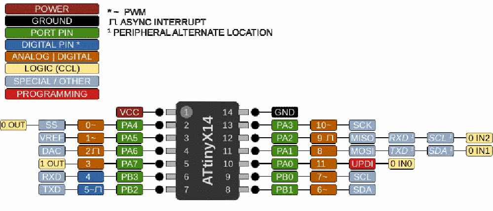
I opened up Fusion 360 and Imported the Attiny I used in week 7. However, the attiny 412 haven’t enough pins for all the functions I want :
Here is the list of the functions I need :
- Communication through I2C (slave mode) to any other microcontroller -> 2 pins (SDA, SCL)
- Communication using the servo RC protocol (PWM) -> 1 PWM pins
- Control the Stepper motor -> 3 Digital pin
- Three led for debug, red, green, and blue -> 3 Digital pin
- Hall effect sensor -> 1 pins
- Total : 10 pins
The suitable ATTiny for that purpose will be the ATTiny 1614 available in the fab inventory. Here is the microcontroller pinout
I created a new project in Fusion 360 named Motherboard I designed the board to be 42 mm by 42 mm to match the NEMA17 stepper motor casing size.
Then I imported the libraries. I first imported the fab.lbr but to my mind, some simple component are missing. I found another library from a fabacademy student online. The fab_new.lbr is much more convenient. This library doesn’t provide the ATTiny 1614, but fortunately I found it online.
I packaged all my component into one single library available at the end of this page.
I added a new part for the hall effect sensor. As the sensor won’t be directly mounted on the board, I will just create a 3 pin JST connector. We may need other type of sensor on this board.

I plugged one of the pin to the VCC (5v - 250mA), another to the GND, and the last one will be directly plugged to the attiny as an input.
We will also need a power input for this board. I added a two ways power block. I will supply the board with 12V to handle the Stepper motor. According to the Attiny datasheet, can only operate between -0.5V and 6V. By the way, I’m curious on how it operates between -0.5V and 0V :D
We need a voltage regulator to convert the 12V power supply to a stable 5V voltage. We could use 3.3V for instance but for compatibility reasons, 5V is better. As the 5V circuits will only provide current to the hall effect sensor and to a bunch of LED, I selected a SOT23 sized regulator available in the Fabinventory.

This regulator can handle up to 30V and supply 5V 250mA to the board. The regulator need to be mounted with two capacitor juste like that :

To know if the board is powered, I will add a red LED directly between the 5V output and the GND. This LED will be mounter with a 1k Ohm resistor


To program the board, I will be using the UPDI pin. Please refer to week 9 to know more about AtTiny programming.

I added the 3 debug LEDs the Stepper motors driver. Please see [week 13] to know more about it.
Here is the overall scheme :

After this design part, I just moves the component on the board to draw the traces.

Soldering
After milling my first version of this board, I had to solder everything on it. I started by the attiny, beacause I need free area to operate arround since this component is crucial.

Then I soldered all the resistors and LED. The hall effect sensor as well. As we don’t need a connector for testing I soldered the hall effect sensor directly.
Let’s test that board !
Programming
I tried the same code as the Arduino, and adapted the pinout.
#define LED_PIN 9
#define HALL_PIN 8

void setup(){
  pinMode(LED_PIN, OUTPUT);
  pinMode(HALL_PIN, INPUT_PULLUP);
}

void updateLED(){
  digitalWrite(LED_PIN, digitalRead(HALL_PIN));
}

void loop(){
  updateLED();

}
It worked perfectly well ! The LED light up when a magnet is approached next to the hall effect sensor. It seems to be reactive within a 0 - 1cm range close to the sensor.