Modela MDX20 Machine
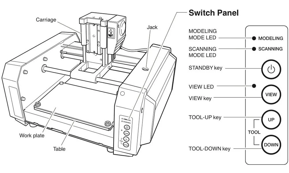
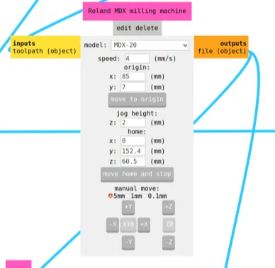
For milling the circuit I used a Roland MDX-20. The Modela MDX20 is a Desktop 3D scanning and Milling machine by Roland. Easy to use,Compatiable with popular softwares.
Work area 203.2 x 152.4 mm
Z stroke 60.5 mm
Spindle speed 6500 rpm
Let's Get Started
I have to learn the details of the milling machine in our lab to mill a In-system programmer.The reason for making FablabISP is not only to know how to make the PCB board and solder, but also to understand it becomes a programmer at the end.
Understanding AVR ISP Programmer
In System Programming
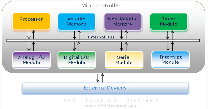
In system programming means basically it allows to program into the board which is AVR micro-controllerAVR micro-controllerAVR is a type of the micro-controllers. Fundamentally, a micro-controller works like a computer, but the physical shape is like a chip. The difference between them is the works that Micro controller is able to do are fewer than computer. The image below is a basic diagram of AVR micro controller.
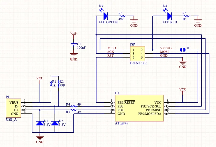
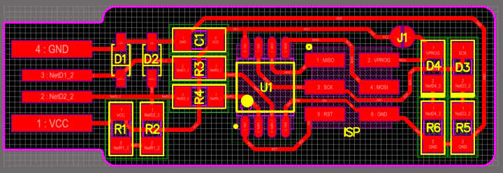
FabISP is an in-system programmer for AVR micro controllers. There are different versions of ISP's available in the archive. I selected Brians Version of Fab ISP called "FabTinyISP".


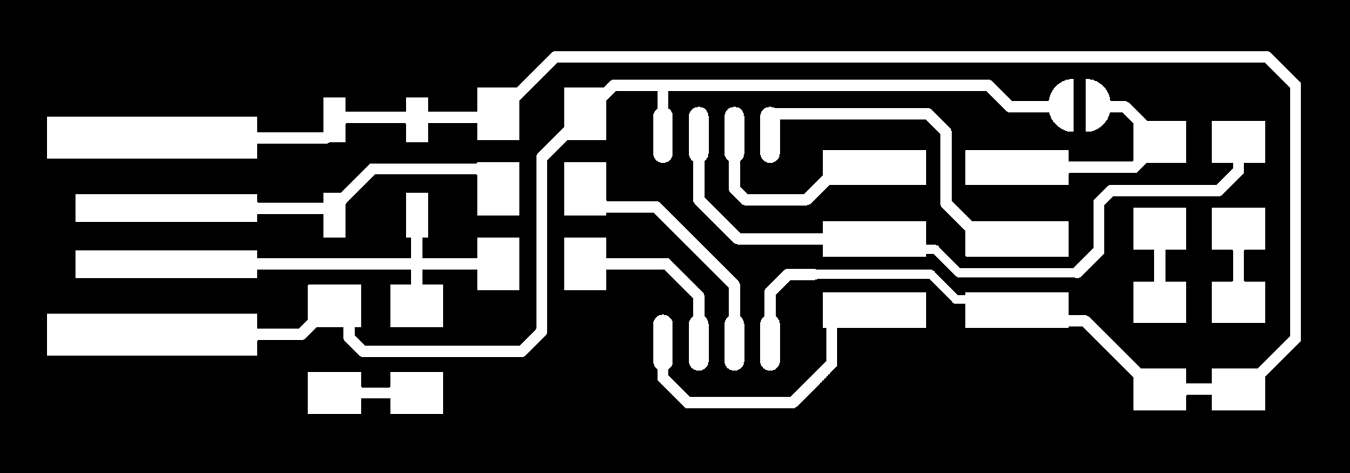
Let's Mill
Milling work is divided into two phases:
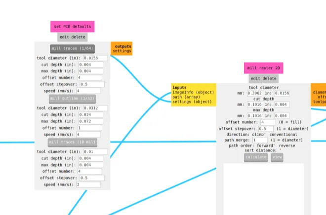
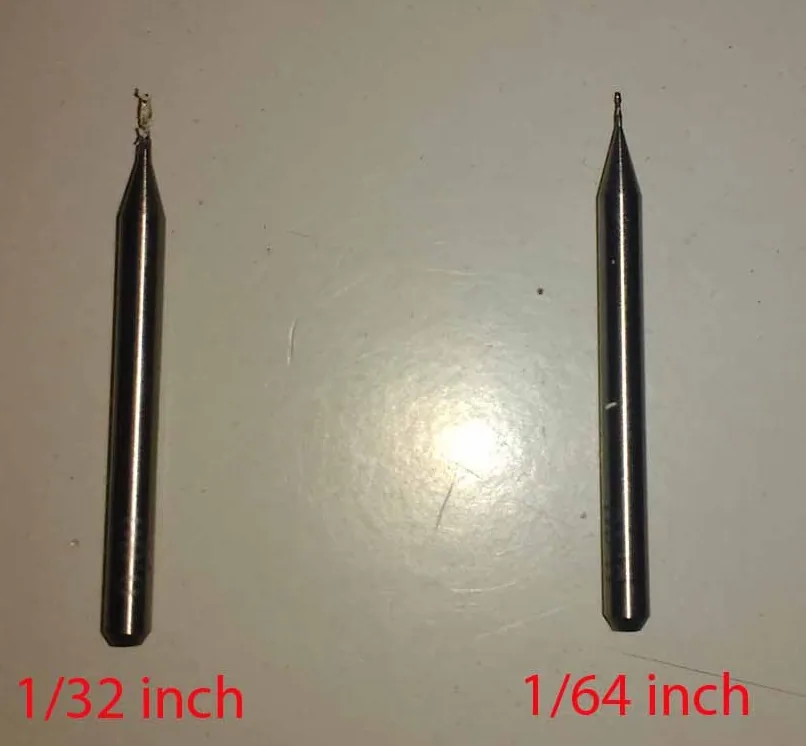
1.milling the PCB traces(1/64)
2.milling the out line (1/32)
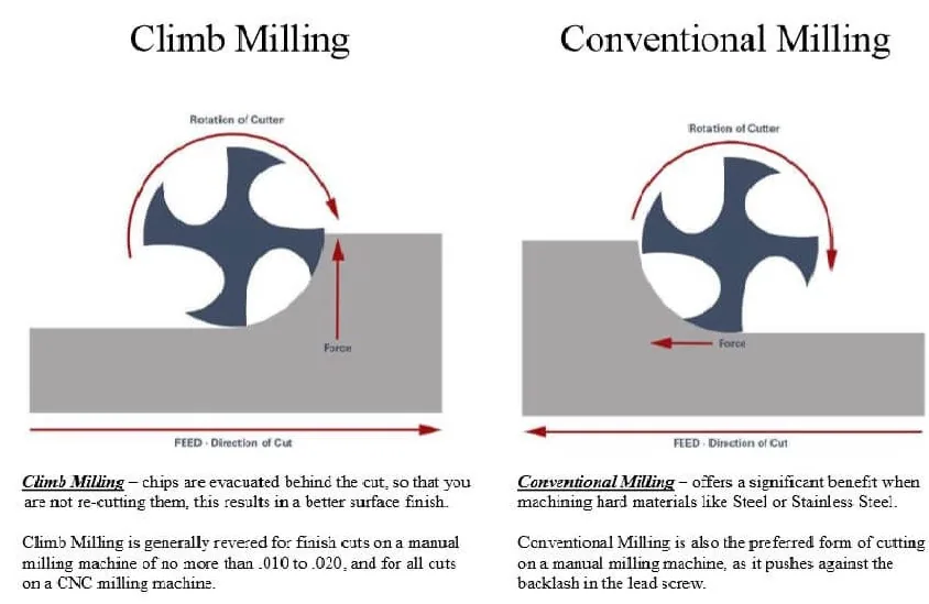
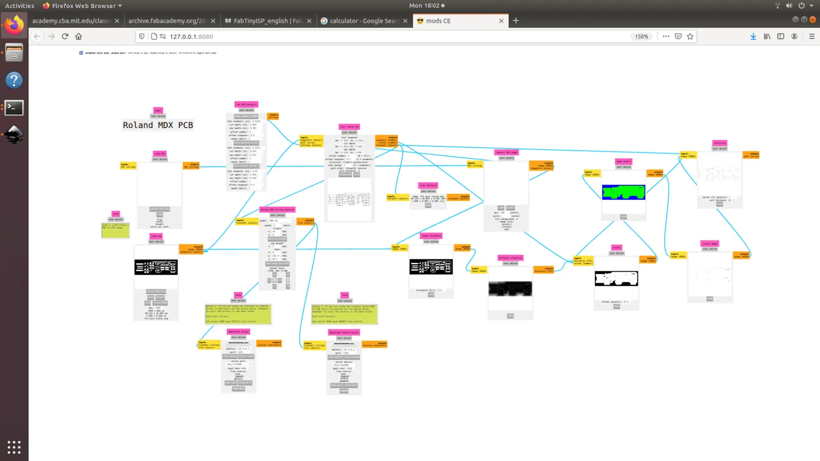
For each of these phases we have to use a different mill drill bit and different settings. We use the fab mods to give commands to the Modella and run the cutting program. This machine is very delicate and the bits are very fragile, take care in removing the milling cutters and correcting the zero setting.Modella MDX 20 is just like any other CNC mechine. We use the same fab modules which we used in vinyle cutting for milling also.
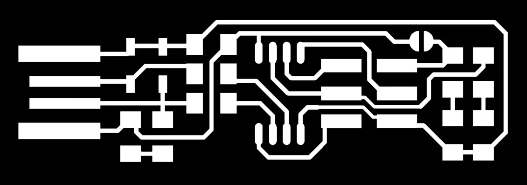
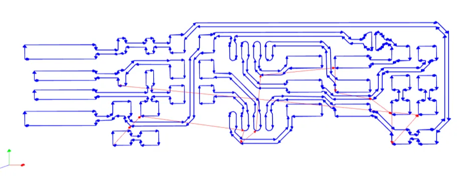
The fab module converts the .png image we give into a series of tool paths, these tool paths are defined by their coordinates. The .png image is a black and white layout of the board, and the black portions will be milled and the white portion is where the copper will be left.
Inn-order to complete the PCB manufacturing process we have to do 2 process
Tracing-Here we trace out all the circuit paths .For milling traces, we use the 1/64th inch (0.4mm) bit
Cutting-Here we seperate the functional part of the pcb fram unwanted ares.for cutting we use 1/32th (0.8mm) inch bit.
Setting up the Machine
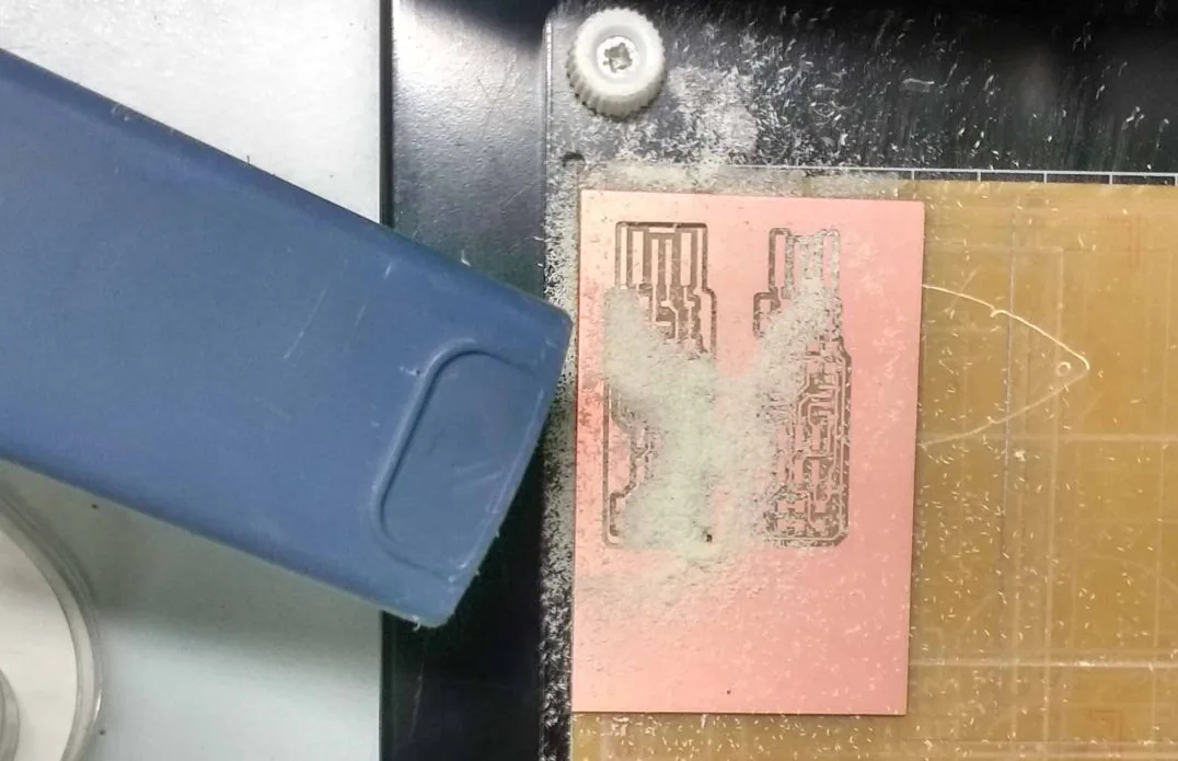
Clean the PCB and Fix it to the CNC sacrificial layer with a double side tapes.Please make sure that the whole milling portion of the pcb is fixed to the table with the tape .If not the pcb may miss Aline and may damage the cutting bit or the pcb itself.1st we were suppose to prepare the sacrificial layer.But we already had a sacrificial layer .So I decided to go with it.
An L-key is used for releasing the bit from the chuck.
To set the Z-value correctly , we can use multiple ways but the most efficient and easiest way i think is
>Raise the Z axis to the top
>Release the chuck using the L-key
>Insert the 1/64 inch milling bit a little more in to the chuck tight the screw
>Down the z axis close as possible to the bed
>Unscrew the chuck and release the bit
>Slightly press the bit close to the bed and tight the chuck screw
Soldering the PCB
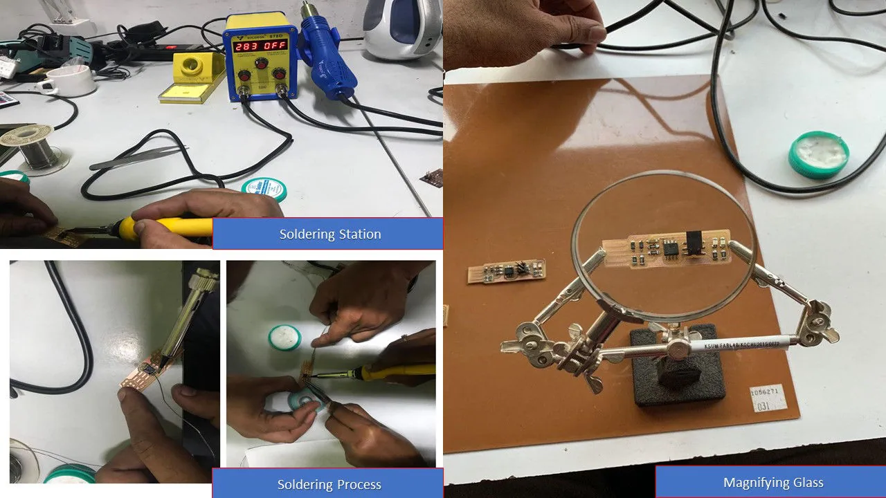
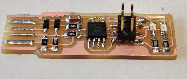
I have very little experience in soldering components that too not surface soldering.The very first step is to collect all the required electronic components and should stick it against a list of components written in a sheet of paper. I had used a single sided tape to stick components with a little bent at each ends to stick it with the paper. The tape will keep the components in place and it will reduce a lot of confusions in future.
Programming the PCB
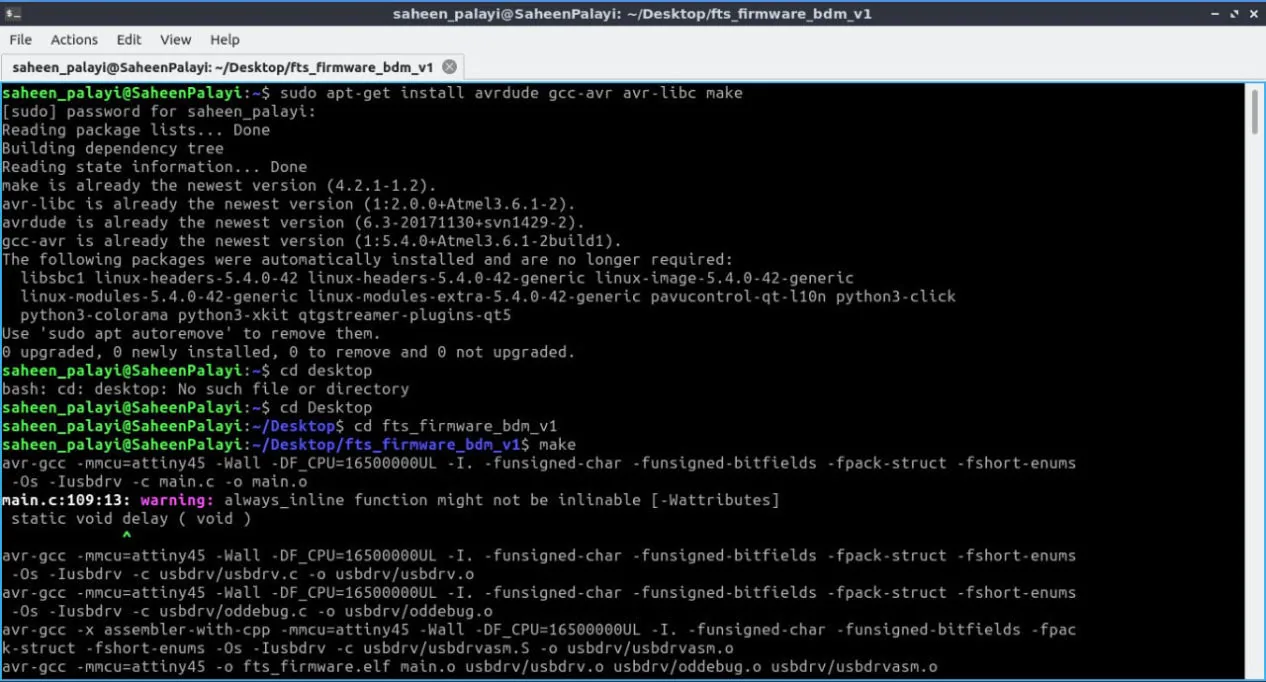
Once you finish soldering the components, It is time to test the connections and program the board. Look carefully at the board to see if all the connections are proper. For Programming I referred the link First we need to install all necessary software for programming, which include "Avrdude" and "GCC" To install these softwares in Ubuntu(since i don't have Ubndtu ,I have done this on my colleague(Saheen P) laptop ),
Open the terminal and follow the steps :
sudo apt-get install flex byacc bison gcc libusb-dev avrdude
sudo apt-get install gcc-avr
sudo apt-get install avr-libc
sudo apt-get install libc6-dev
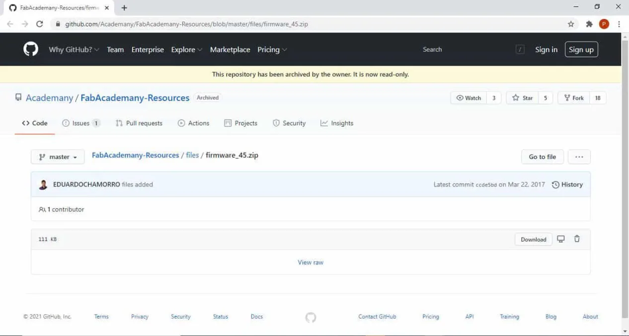
Now we need to download and unzip the firmware To download and unzip the FABISP firmware, Open the terminal and follow the steps :
cd ~/Desktop
wget http://fab.cba.mit.edu/classes/863.16/doc/tutorials/fabisp_programming/fabISP_0.8.2_firmware.zip
unzip fabISP_0.8.2_firmware.zip
The "Makefile" in the downloaded firmware is set up to work with AVRISP2 by default, Since we are using Atiny45 this firmware wont work. So you can use this file.
Now connect the ISP with the mother ISP which is already programmed via jumper cable. Connect in such a way that all the points in both the ISP are exactly same and connect it to the computer via USB port.
Follow the steps to run the device:
Go to the unziped firmware folder and open the terminal.
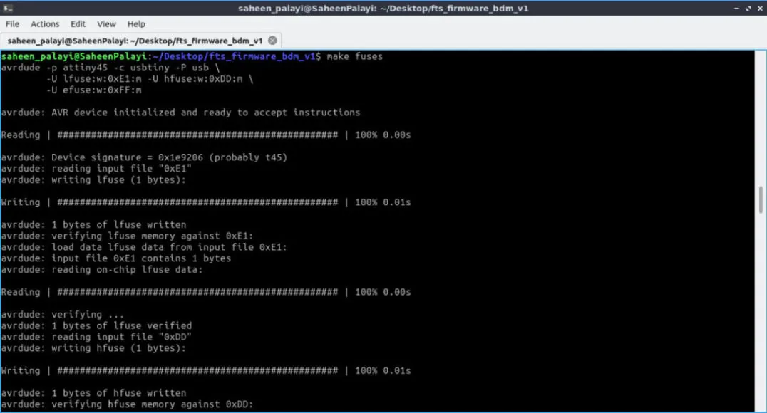
type "make"
type "make flash"
type "make fuses"
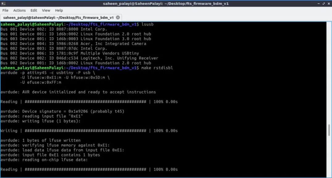
"make rstdisbl"
Blow the Reset Fuse
We need to change the bit that will turn the ATtiny45's reset pin into a GPIO pin.This will disable our ability to reprogram this ATtiny45 in the future, hence make sure everything is working before doing this. Connect your ISP programmer to your board one more time, and in the Terminal run. For that you need to type:
make rstdisbl.
This does the same thing as the make fuses command.with that, avrdude will never be able to talk to this chip again through the ISP header. Now our programmer is finished. To check the disabled pin. We can use the following command.
make flash.
(You can open device manager to know if its properly working)
Done .its Working.....
Group Assignment
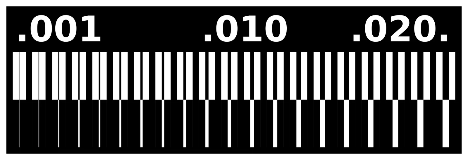
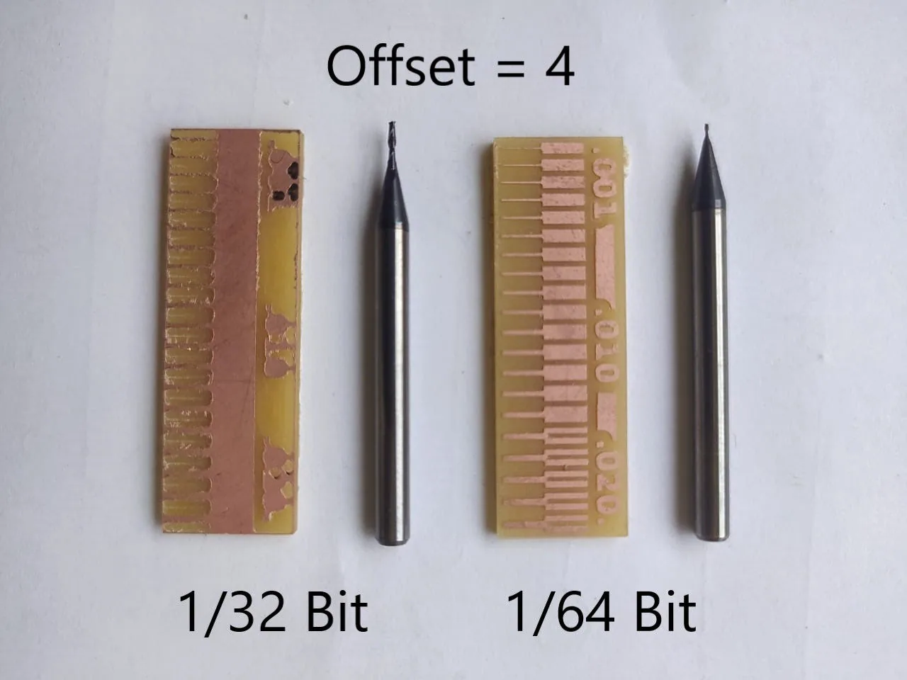
For the group assignment we need characterize the specifications of our PCB production process.Since i exaplined about the production process during my assignment next one is to find-out the resolution of mill bits we are using.
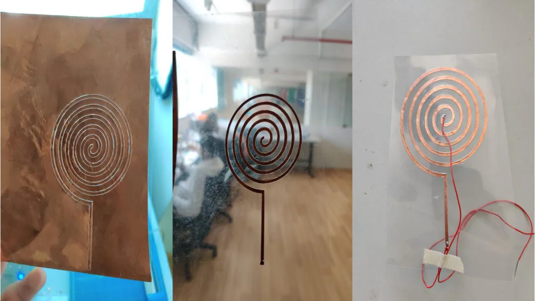
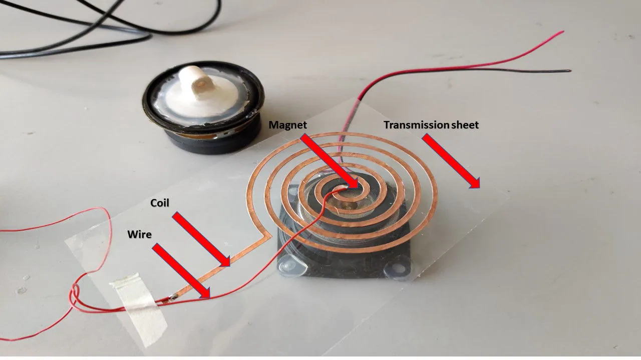
Making a speaker using Vinyl Cutter
The work was inspired from Joao Wilbert's experiment to make speakers using Vinyl Cutting process. Most coil based speakers work through the same principle of using a electromagnetic coil that is connected to a voltage source with the audio signal and a static magnet. Based on this principle I wanted to vinyl cut copper to create a sheet speaker. I selected one of traces from his model with average number of turns, then I had imported that image into MIT Mods. Since I did flexible PCB before it already knew the force and the speed(its 130 g/a and 2 cm/sec. After that with the help of my friend, I had soldered a wire onto the coil and for testing we had connected the coil to a CRO with a magnet unde the sheet to test the speaker. Hurray, it was working as expected, but the sound coming from the speaker was too low, then we found out the reason that the number of turns was too less. In order to test a custom music, I tried to connect the coil onto a audio jack. The steps are explained as follows: