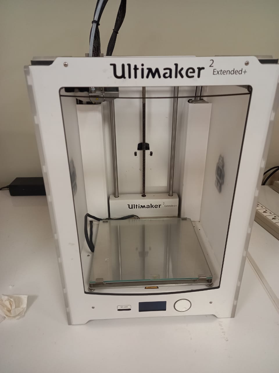
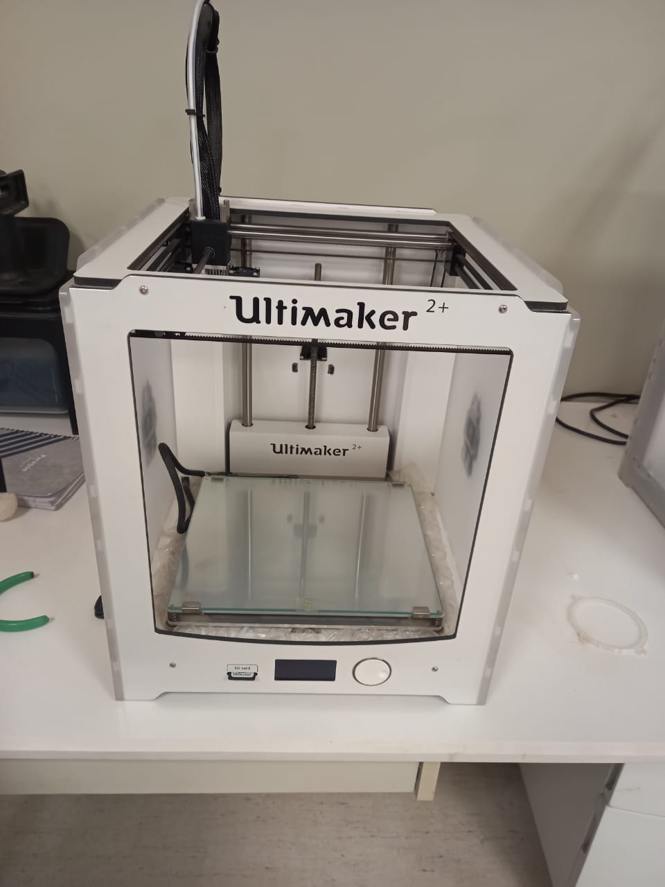
Before Proceeding toward the group assignment our Instructor guide and give brief introduction of 3D Printers avalaible in our lab. Also explain the specification and precauation of using 3d Printers.
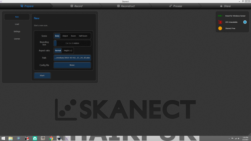
Open the file in cura
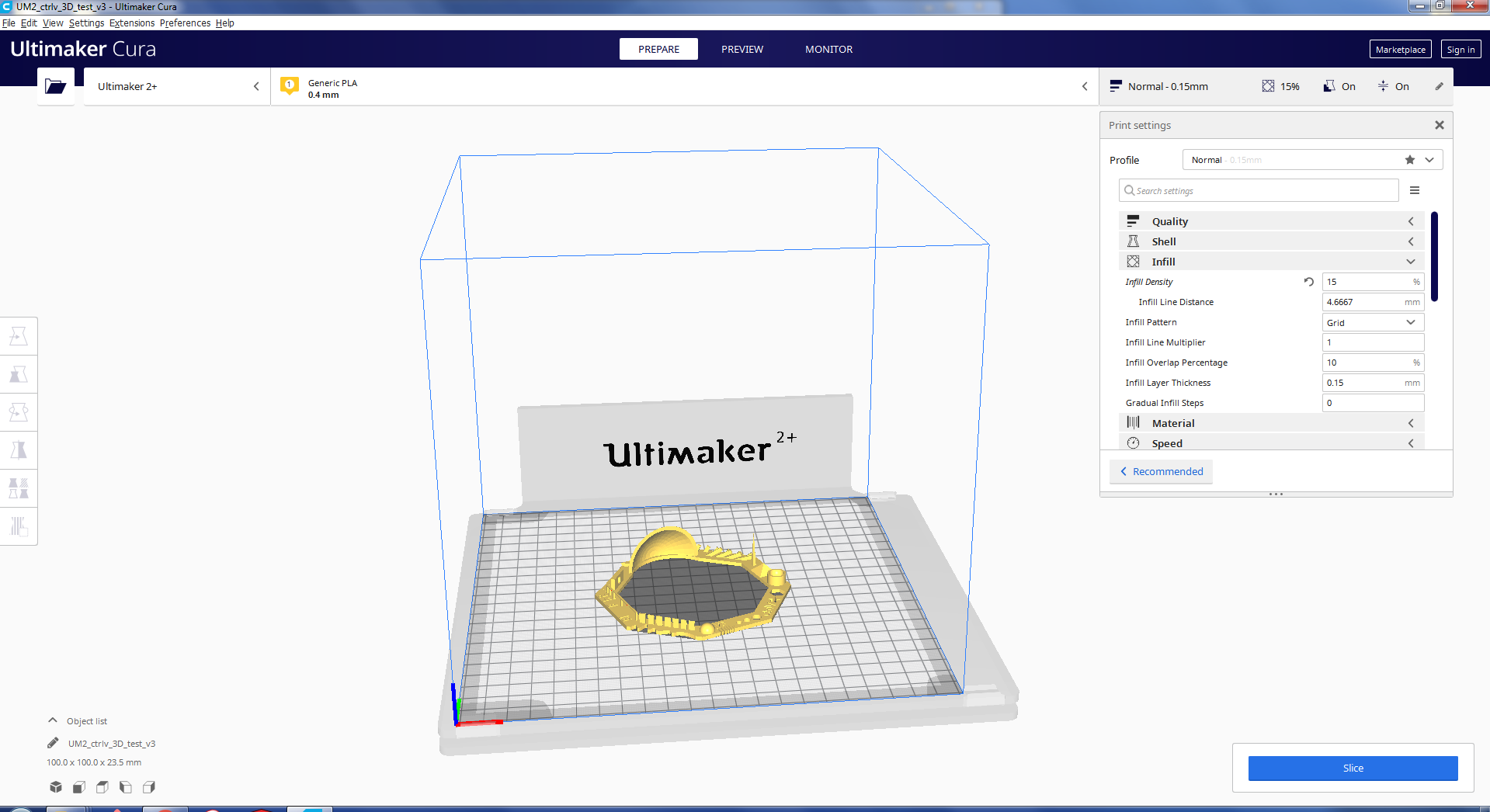
fig:opening the test file in cura to generate G file.
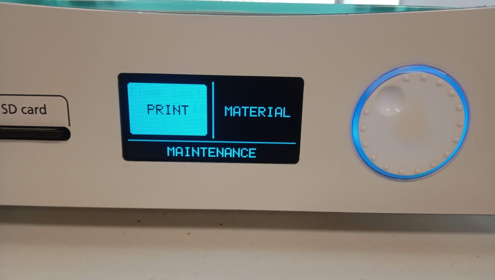
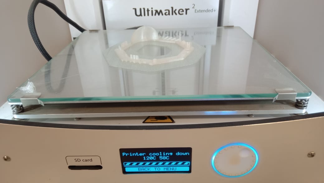
Now we copied the gcode file in the SD card and opened it in ultimaker 2+ and gave commond for print.
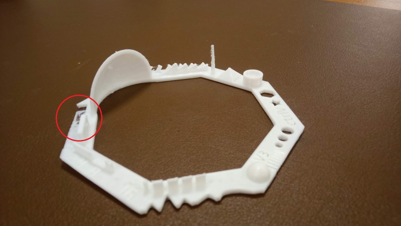
Final result have some misprinting. So, we make another print.
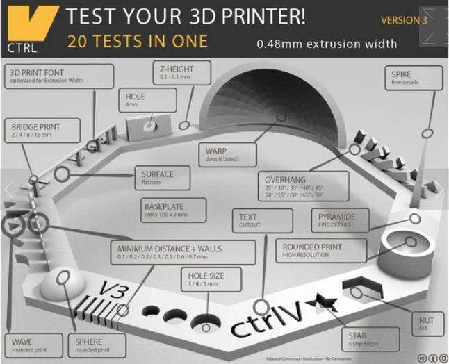
we printed another test card with some print setting there was no support, raft included, resolution 0.1mm or higher and infill was 30%.
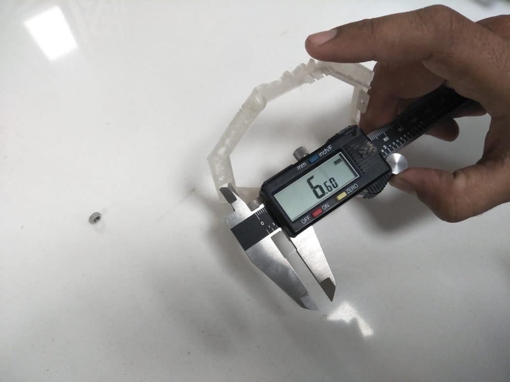
MEASURE THE HOLE IN WALL DIAMETER
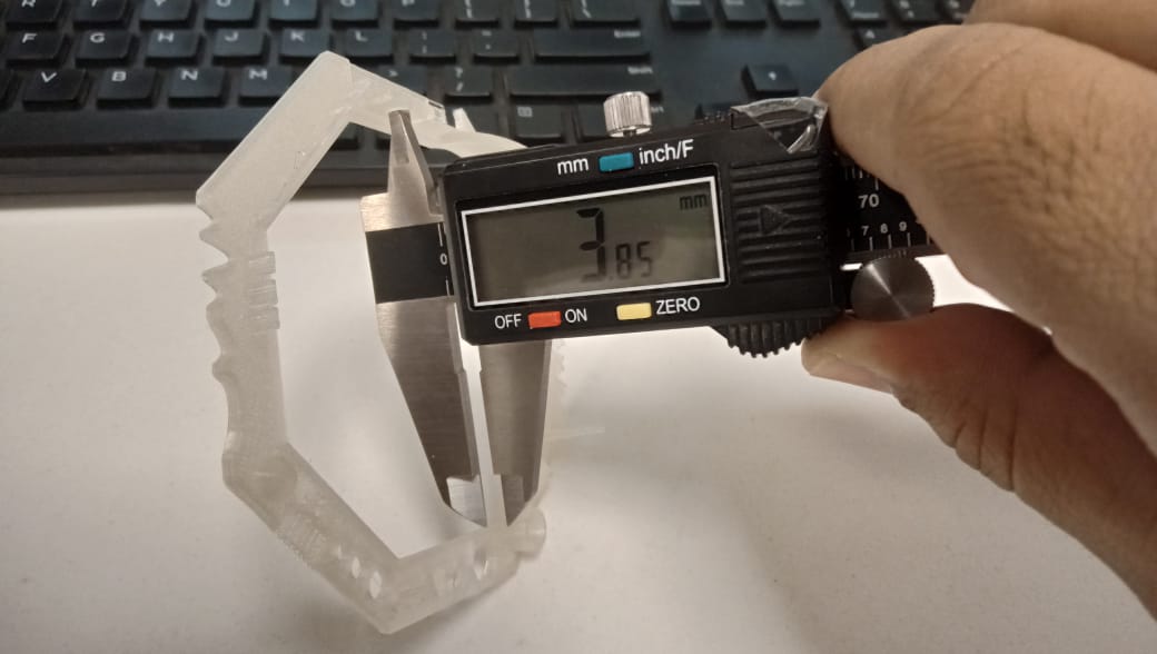
According to test specification the Hole in Wall diameter is 4mm but in actual it is 3.85mm.
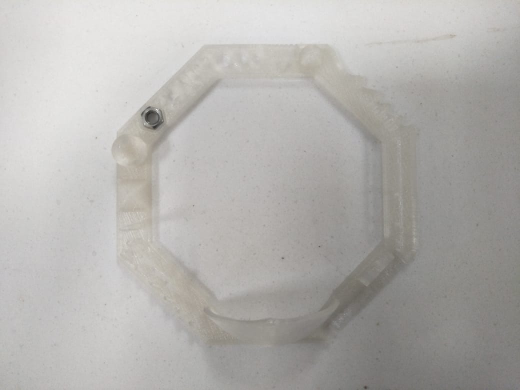
MEASURE NUT SLOT
Checking the nut size in 3D test card we measure nut slot size with the help of vernier caliper.
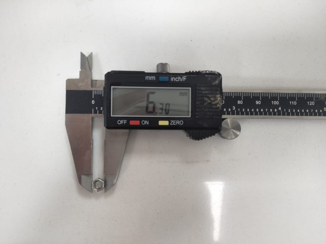
measuring the nut size in mm for checking the 3D test card nut slot.
We can observe that there is the approximetly 0.30mm difference between nut and slot.
MEASURE THE PYRAMID
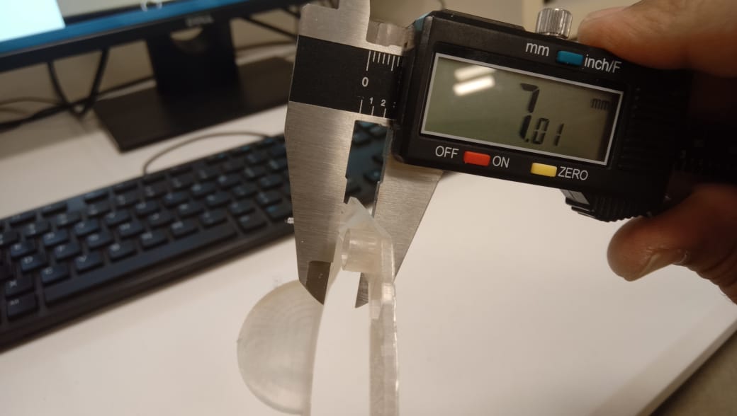
In pyramid there is only 0.01mm difference actually it is 7mm but when we measured it was 7.01mm.
Individual assignment
As the individual assignment were to design and print an additive 3d object and scanning of any object.
I start with to design the additive object. After visiting the page of previous students and with the suggestion of my instructor i decide to design an subject such that a ball inside a box having windows at all sides and the ball will move freelly inside the box and can't come outside from the box.
I start from the solid work for designing of the parts ( Base, walls ,and Balls)
open the solid work sketch the Base and extrude the base
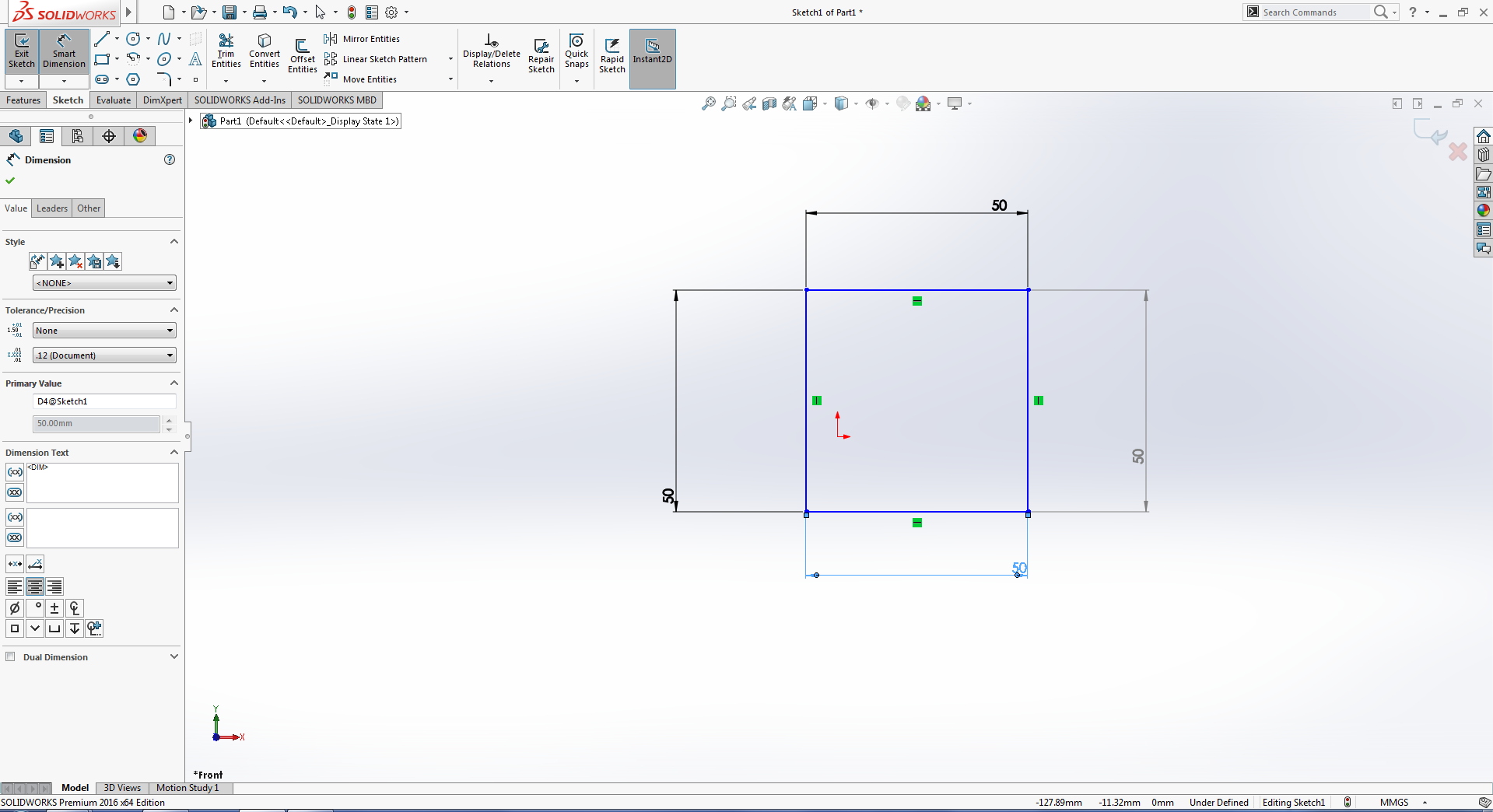
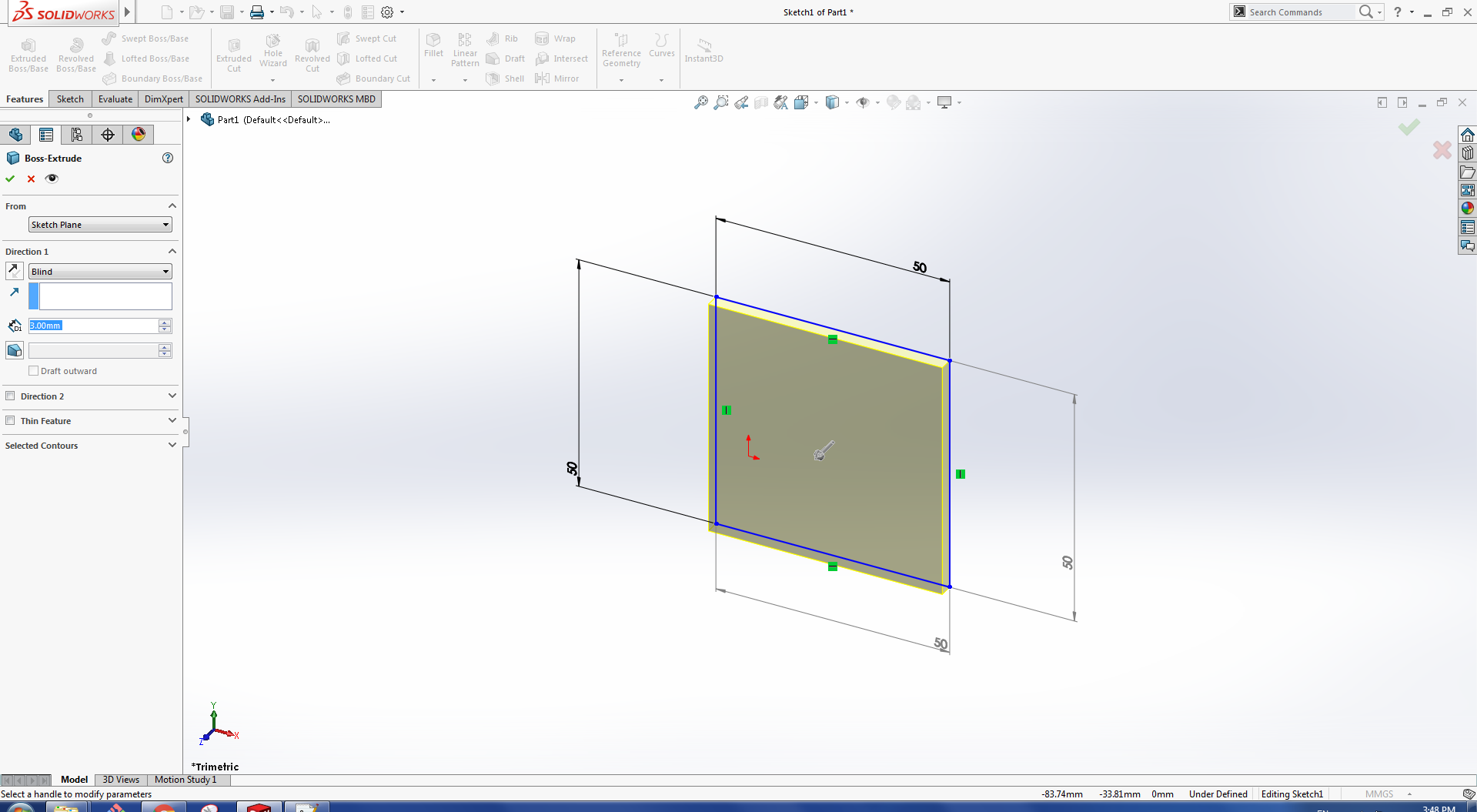
fig:drawing and extrude of rectangle for base.
After that I made the wall having windows for the box
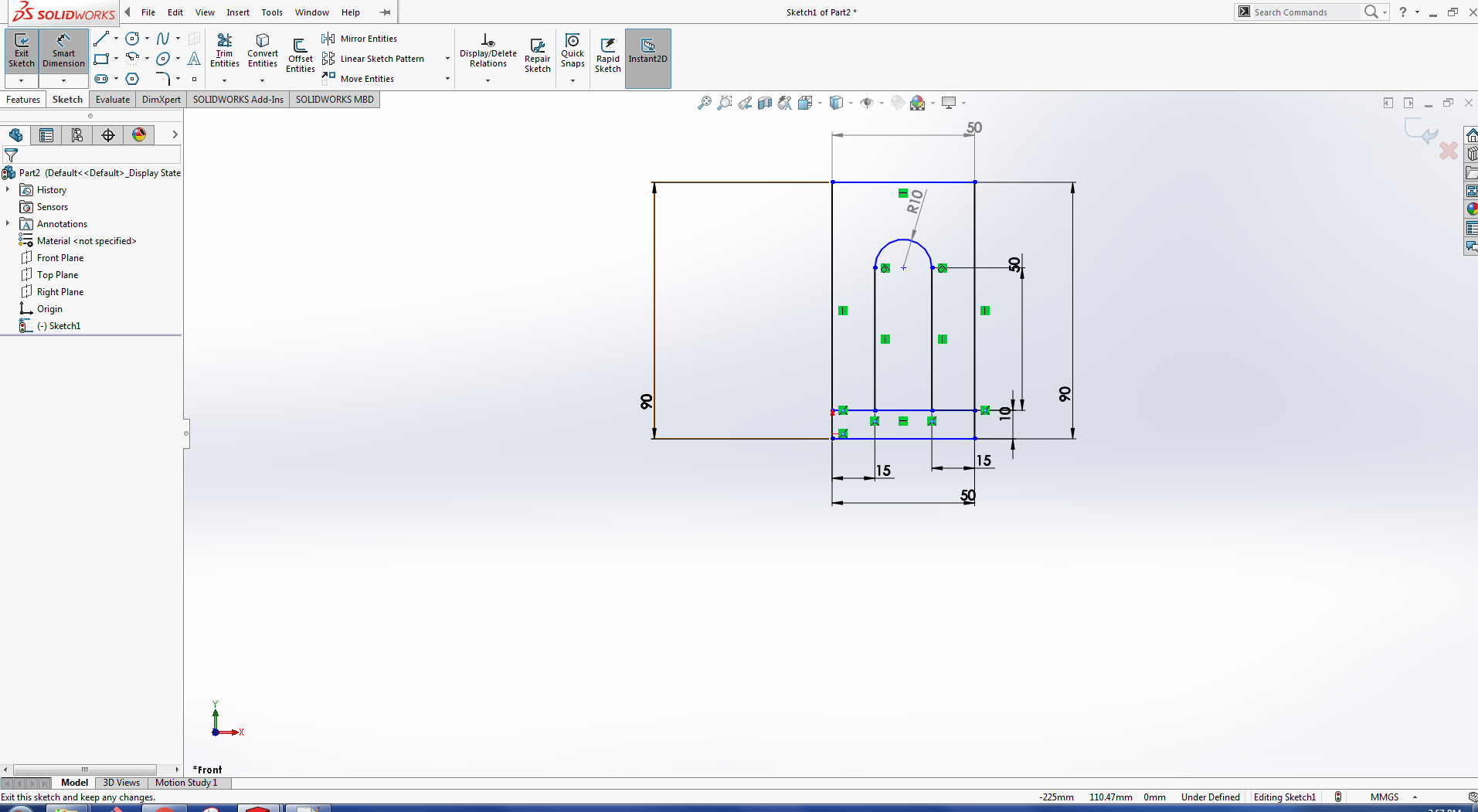
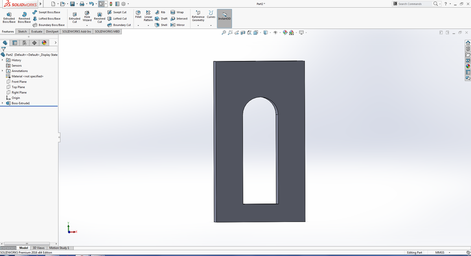
fig:drawing and extrude of rectangle for the window of the box.
Then I made the ball in solid work by using Revolve Feature
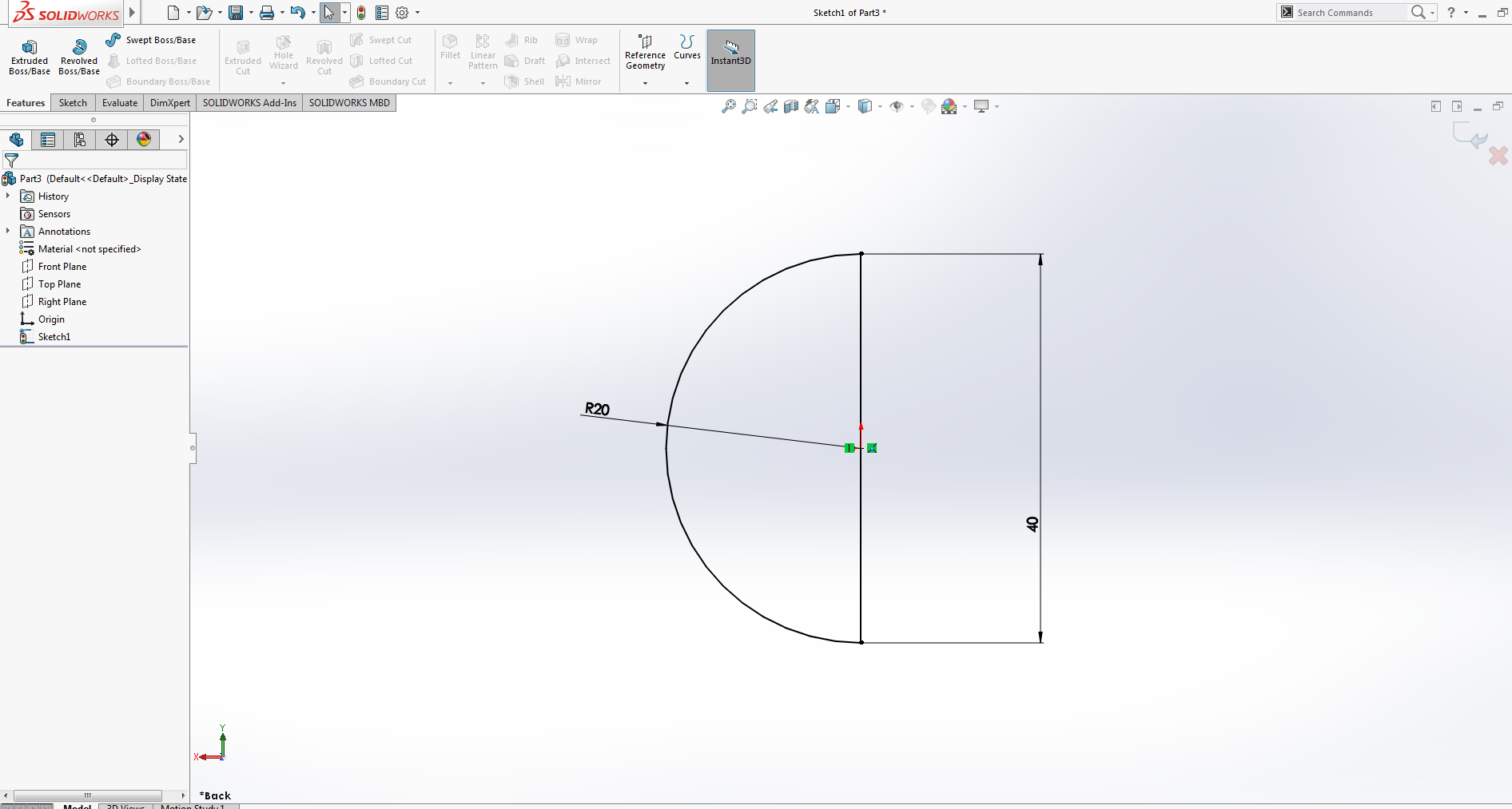
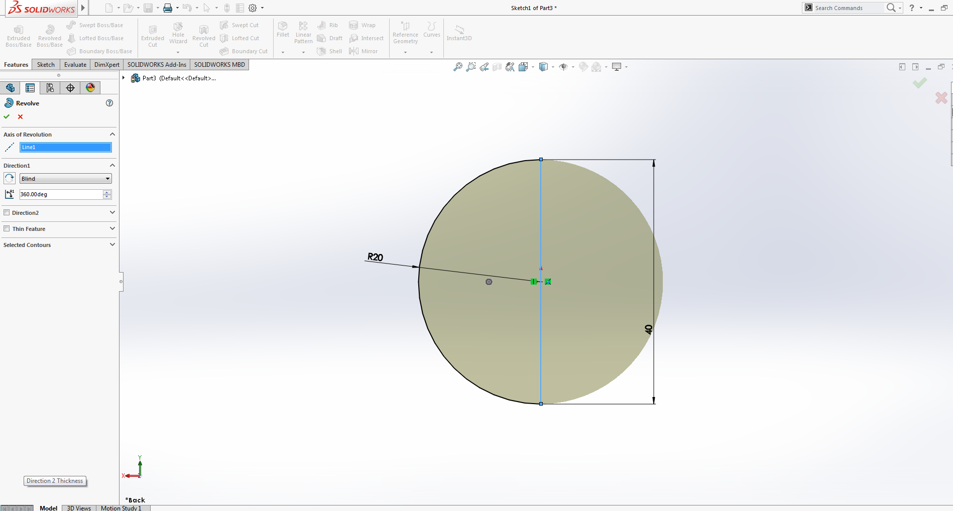
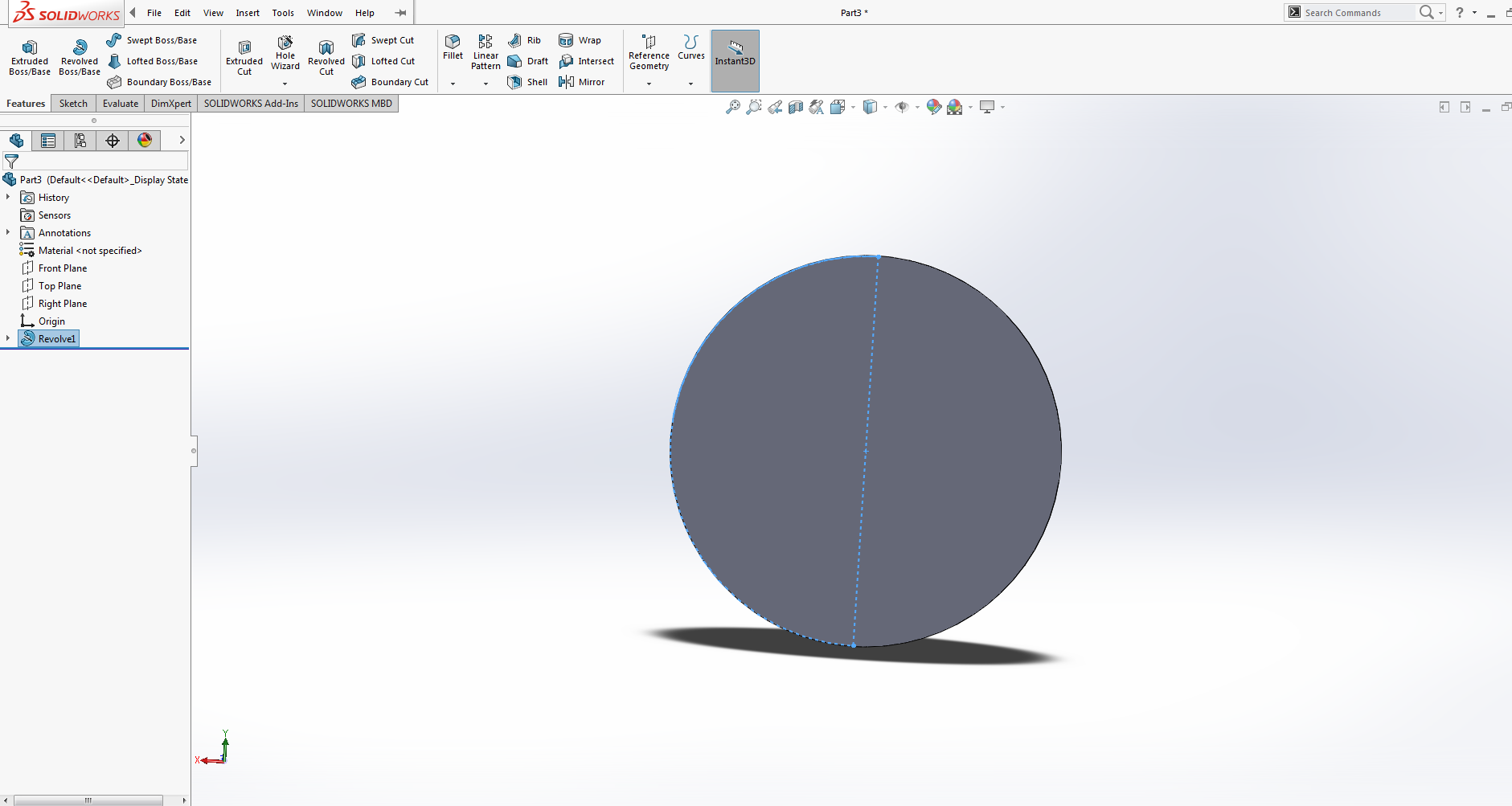
fig:drawing and Revolve Using center piont arc for the ball
And Then I open the assembly and assemble all the parts.
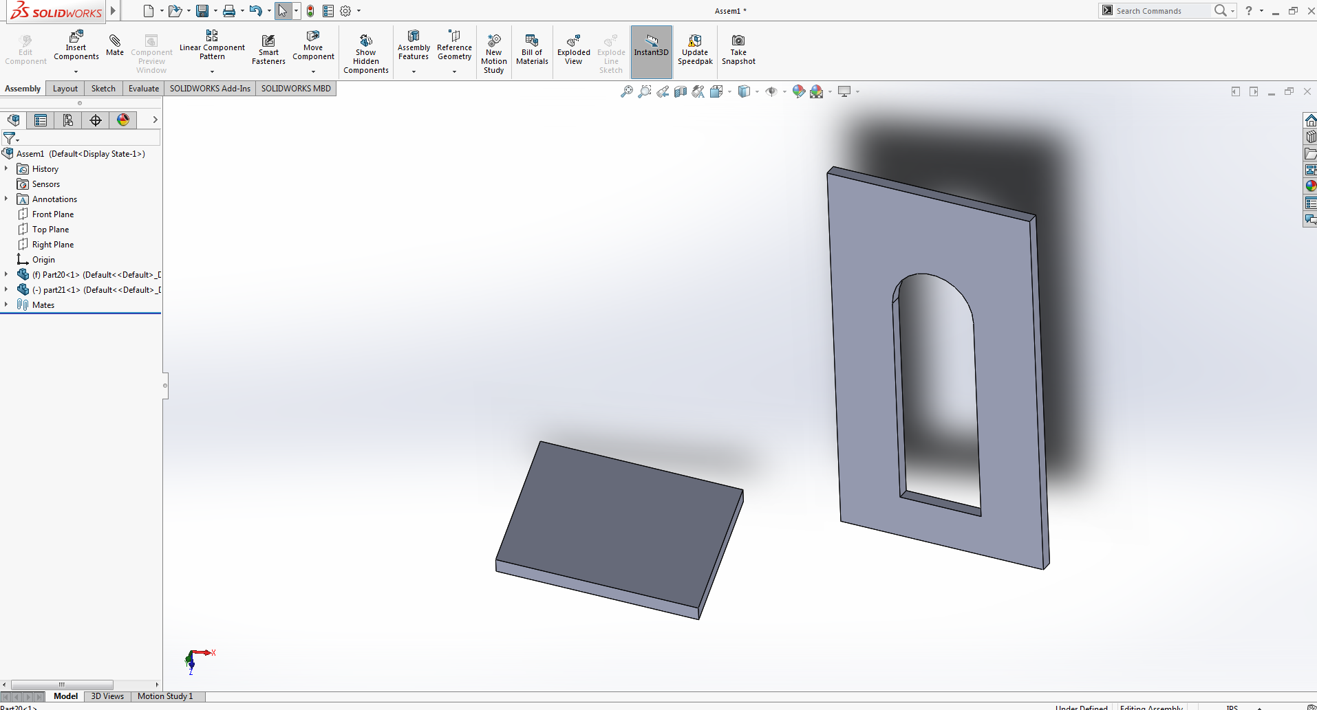
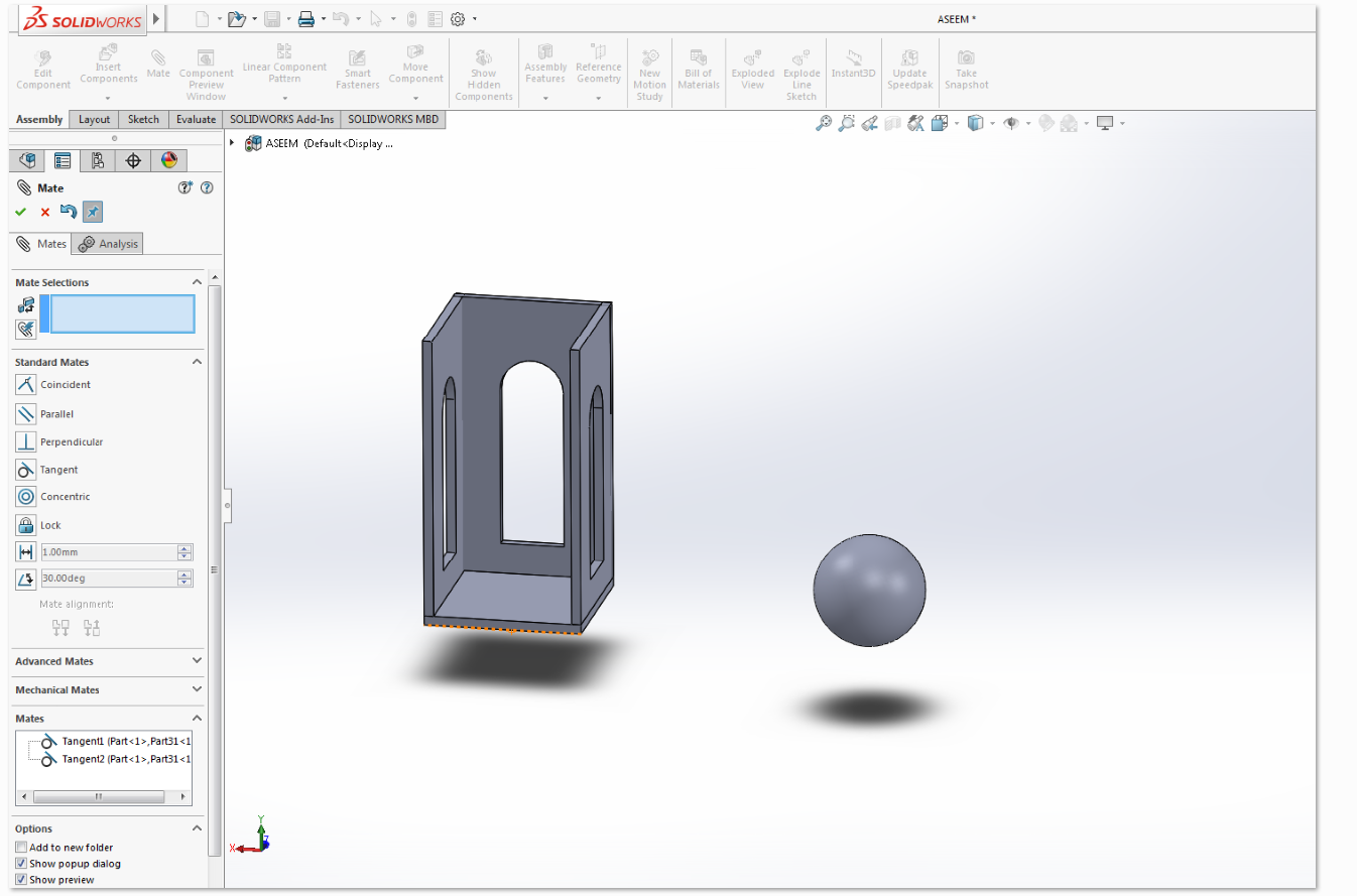
fig:assembling of the base and window and inserting the ball
And The Final look of the box having ball inside is as.
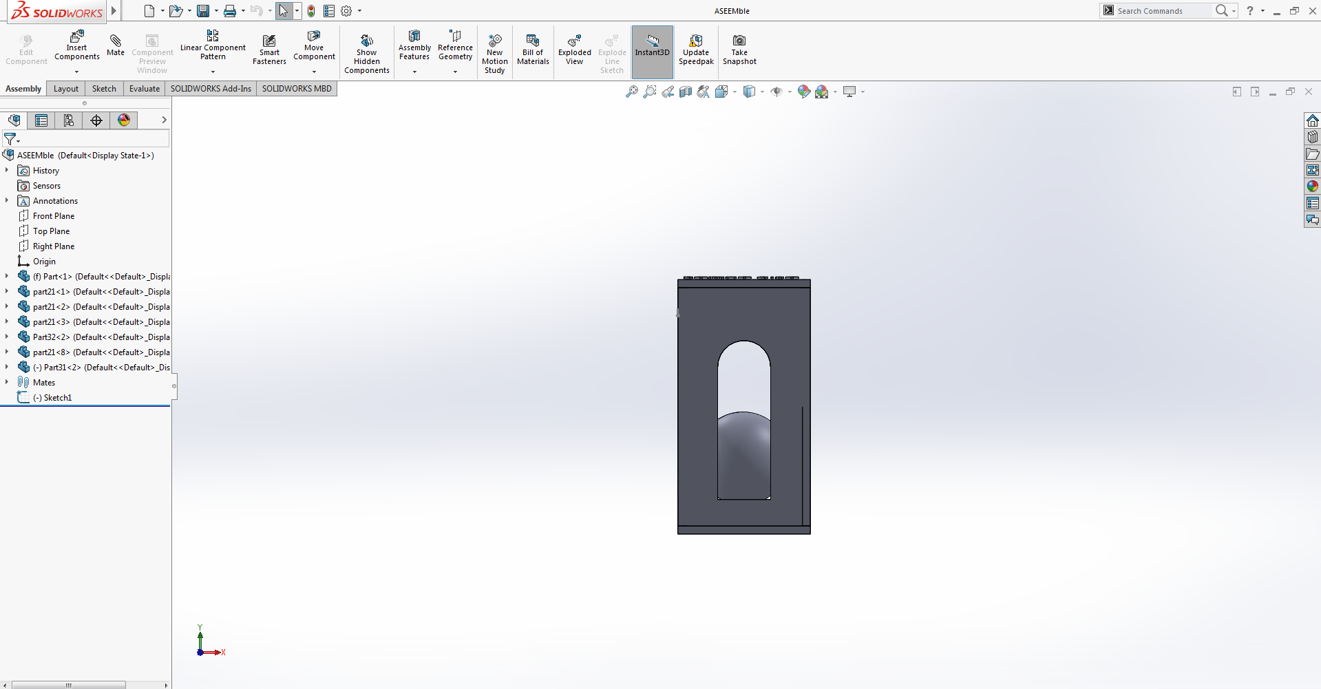
fig:Screen shot After assembling.
Now save the file in the solid work with stl extension
Now the final step is to export the model to Cura for printing after some necessary setting
Cura is an open source slicing application for 3D printers. It was created by David Braam who was later employed by Ultimaker,
a 3D printer manufacturing company, to maintain the software. Cura is available under LGPLv3 license.
Cura was initially released under the open source Affero General Public License version 3,
but on 28 September 2017 the license was changed to LGPLv3.This change allowed for more integration with third-party CAD applications.
Development is hosted on GitHub.[2] Ultimaker Cura is used by over one million users worldwide and handles 1.4 million print jobs per week.
It is the preferred 3D printing software for Ultimaker 3D printers, but it can be used with other printers as well.
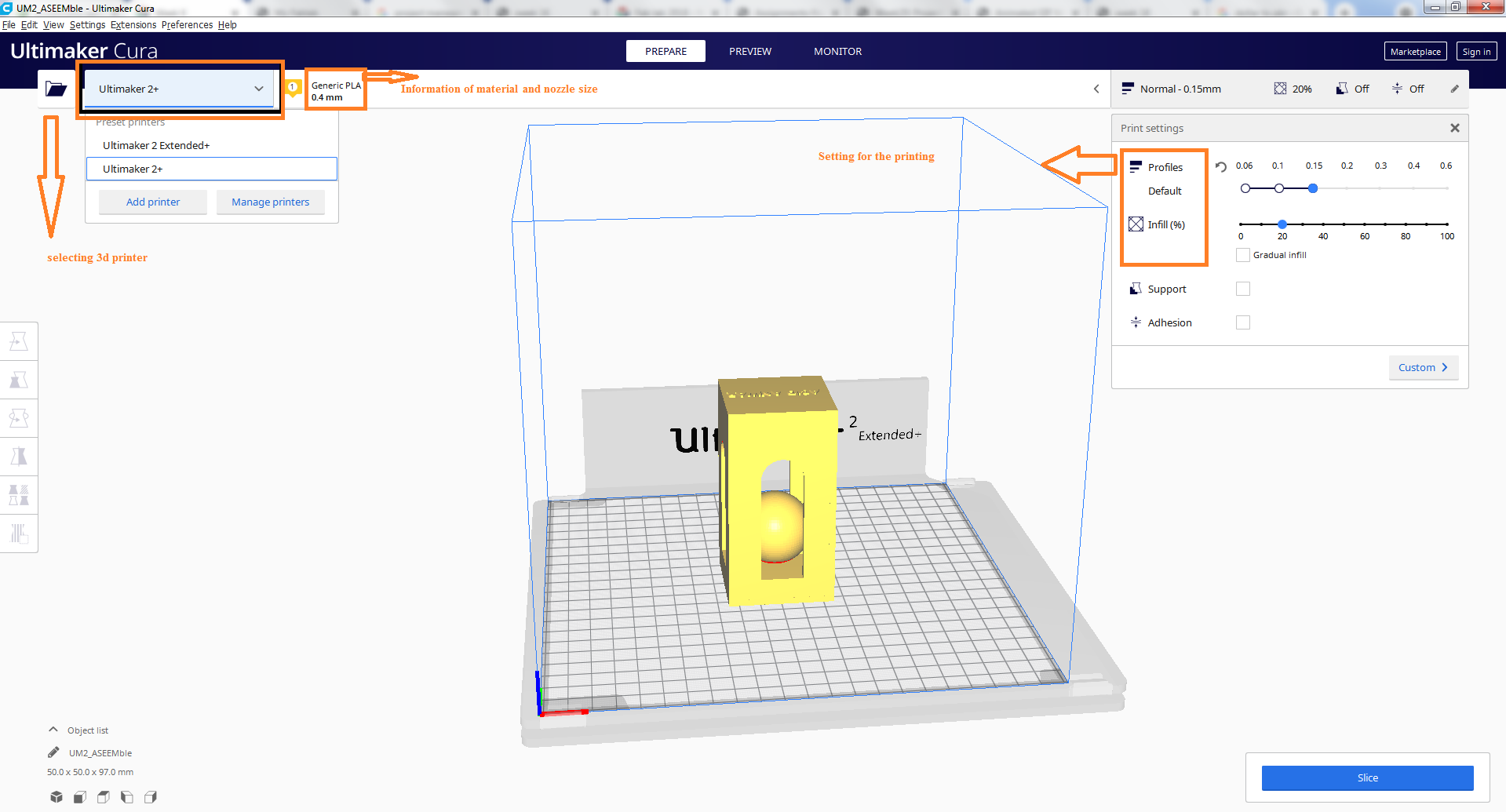
We can custom change the type of printing detting in Cura as:
opening the file in cura.
Setting In CURA
As the Cura give us alot of option for setting
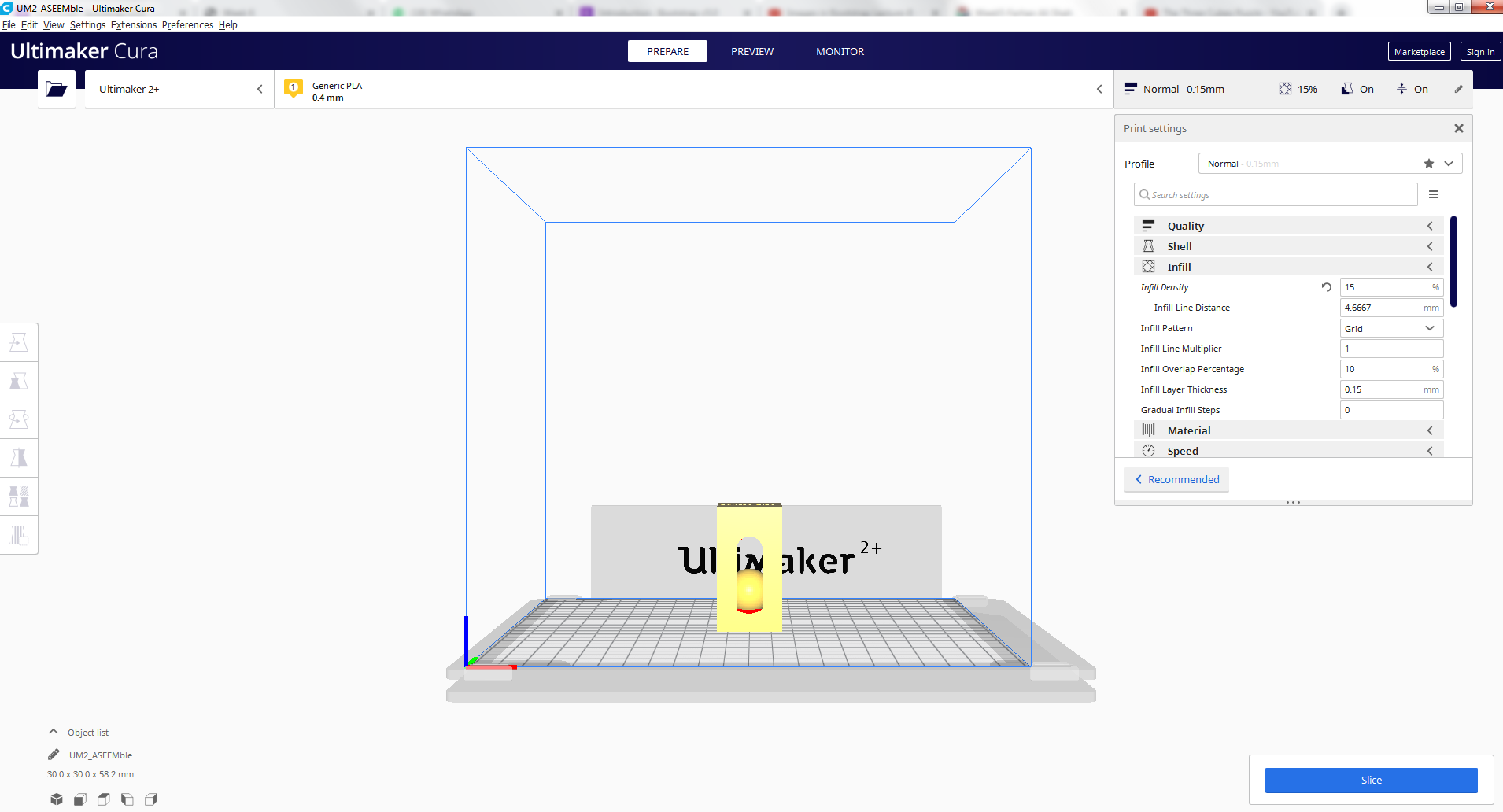
Based on this model, we decided that the best settings for a test print in PLA on Ultimaker 2+
I decided that the best settings for a final print in PLA on Ultimaker 2+ was: 0.15 mm layer height,
I decided that the best settings for a line width: 0.35mm layer.
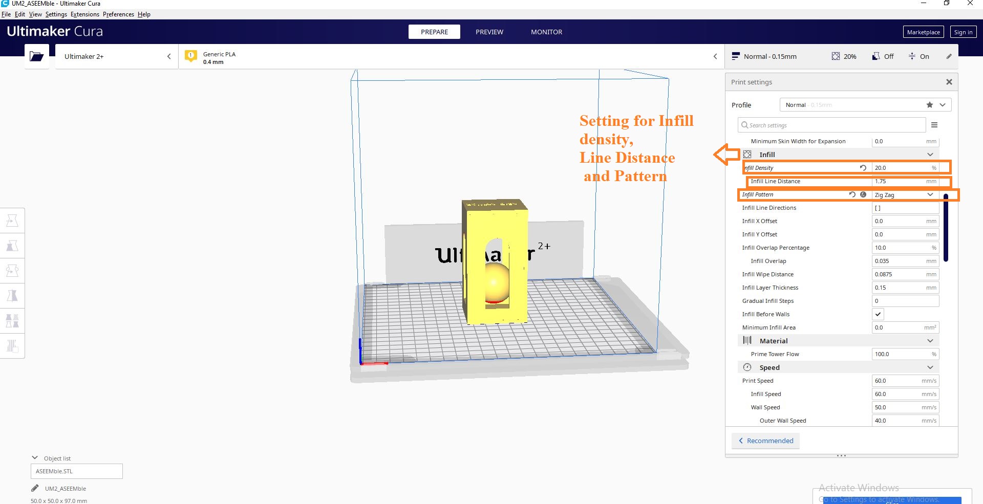
I decided that the best settings for infill density is 20% as in 20% it was rigid enough to have a good result and less then that may cause the result not so good and greater then this value may be the waste of material:
My Instructor guide me to have the zigzag pattern for this design so have good result and done in less time .
I decided that theprofile will normal 0.15 as the result in this was good and it was enough to be rigid.
I decided the support will be normal and the placement should touch the buildplate.
And the Support Pattern should be the Zigzag.

Setting in cura.
Now the printer is ready to start and show the approxiamate time for the printing
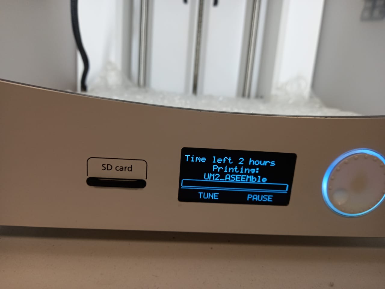
fig:Printer showing the expected time for the printing
After printing and with support
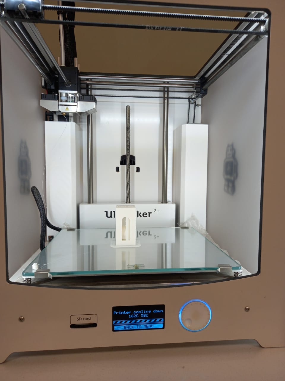
fig:the printed model with support.
After removing the support the final result is as
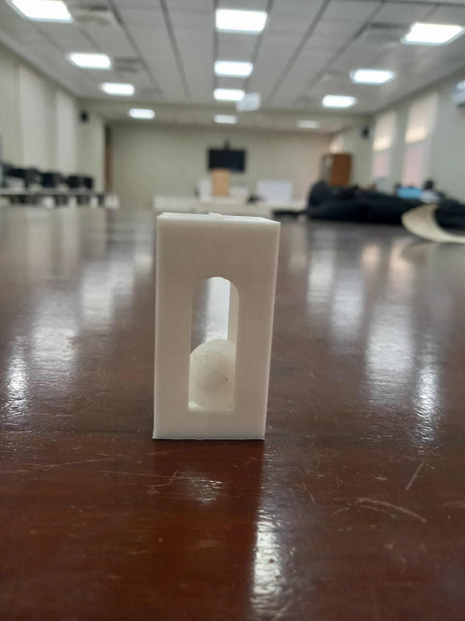
fig:After removing the support the final printed object.